Thomas Petazzoni is Bootlin's co-owner and CEO. Thomas joined Bootlin in 2008 as a kernel and embedded Linux engineer, became CTO in 2013, and co-owner/CEO in 2021. More details...
Initially planned to take place in Dublin, Ireland, the unique edition this year of the Embedded Linux Conference will take place in Seattle, US and virtually from September 27 to September 30, 2021. See also the conference website. Bootlin CEO Thomas Petazzoni is again a member of the program committee for this edition of ELC.
This kind of event is only possible thanks to the talks proposed by its participants! As detailed on the Call For Papers, the last date to submit your proposals is June 13, 2021. There is really a wide range of suggested topics, and ELC is an excellent place to talk about advancements in the Linux kernel for embedded platforms, in user-space libraries and stacks relevant to embedded, about practical experiences in using Linux in embedded devices, about real-time, boot time, power management, build systems, open hardware, and more.
Bootlin has been offering for several years a Buildroot system development course, which allows engineers interested in learning and understanding the Buildroot embedded Linux build system to get up to speed very quickly.
In preparation for our public Buildroot system development course next week, we updated our training materials, both slides and labs to Buildroot 2021.02, which is the latest stable Buildroot release as of today, and is also a Long Term Support release.
In addition to updating to a newer Buildroot version, we also use newer U-Boot and Linux versions for the practical labs on BeagleBone Black Wireless. The slides were also updated to document some new features that appeared between 2020.02 and 2021.02. If you’re interested, check out the materials on the training page.
We have one seat left for this training course next week, which will be taught by long-time Buildroot contributor and developer Thomas Petazzoni. Register now and take the last seat!
The schedule for the next edition of Live Embedded Event has been published! This 100% online and free conference will take place on June 3rd, 2021. Thanks to the proposals received, the event will feature 4 tracks during the entire day, covering a wide range of topics: hardware for embedded systems, embedded Linux, RTOS, IoT, FPGA, RISC-V, and more.
Live Embedded Event #2 agenda
Bootlin is once again part of the organization team for this event, and in addition 5 talks proposed by Bootlin have been selected into the schedule. See below the details of our talks.
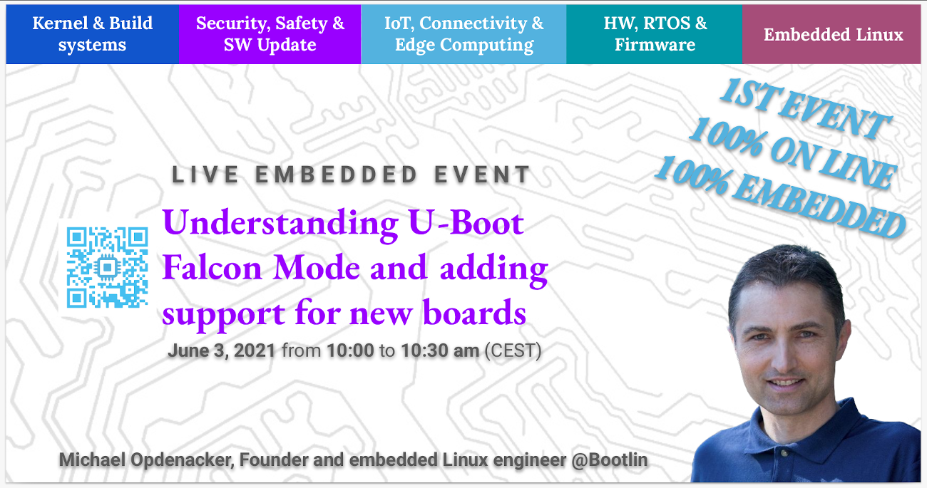
Understanding U-Boot Falcon Mode and adding support for new boards, Michael Opdenacker
The Falcon Mode is a U-Boot feature that allows to directly load the operating system kernel from the first stage of U-Boot (a.k.a. “SPL”), skipping the second stage of U-Boot. Doing this can save up to 1 second in the boot process, and this way, you can keep a full featured U-Boot that you can still fall back to for maintenance or development needs. However, using Falcon Mode is not always easy, as it requires extra code that most boards supported by U-Boot don’t have yet. At Bootlin, we had to add such support to U-Boot for several boards. This presentation will explain how Falcon Mode booting actually works in U-Boot and the implementation and usage choices made by U-Boot developers. It will show you how to add such Falcon Mode support to U-Boot for your own board.
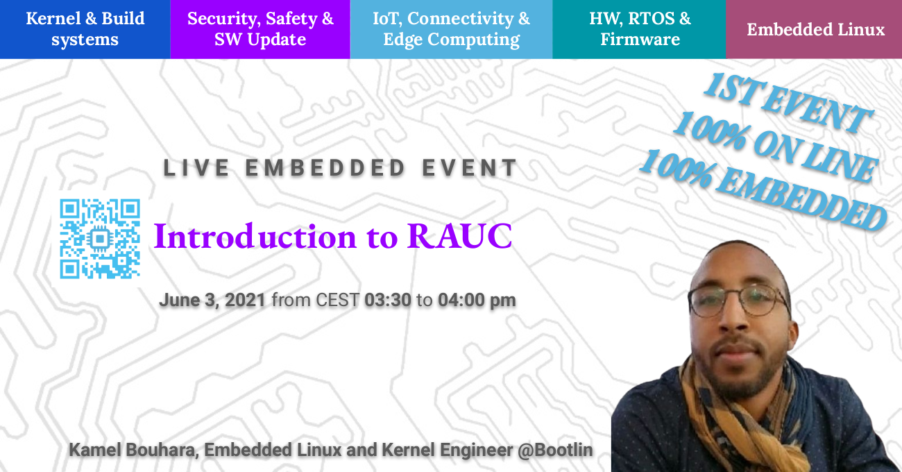
In embedded systems, deploying firmware updates in the field has now become an obvious requirement, to ensure that security vulnerabilities are addressed, that bugs are fixed, and new functionalities can be delivered to the users. Among a range of different open-source solutions, RAUC provides an interesting firmware update mechanism for embedded system. In this talk, we will introduce the main features of RAUC, its integration in build systems such as Buildroot or the Yocto Project, as well as its integration with the U-Boot and Barebox bootloaders. Finally we will explore some common update scenarios that are fully supported by RAUC features.
Talk given by Kamel Bouhara, at 3:30 PM CEST on June 3rd, 2021.
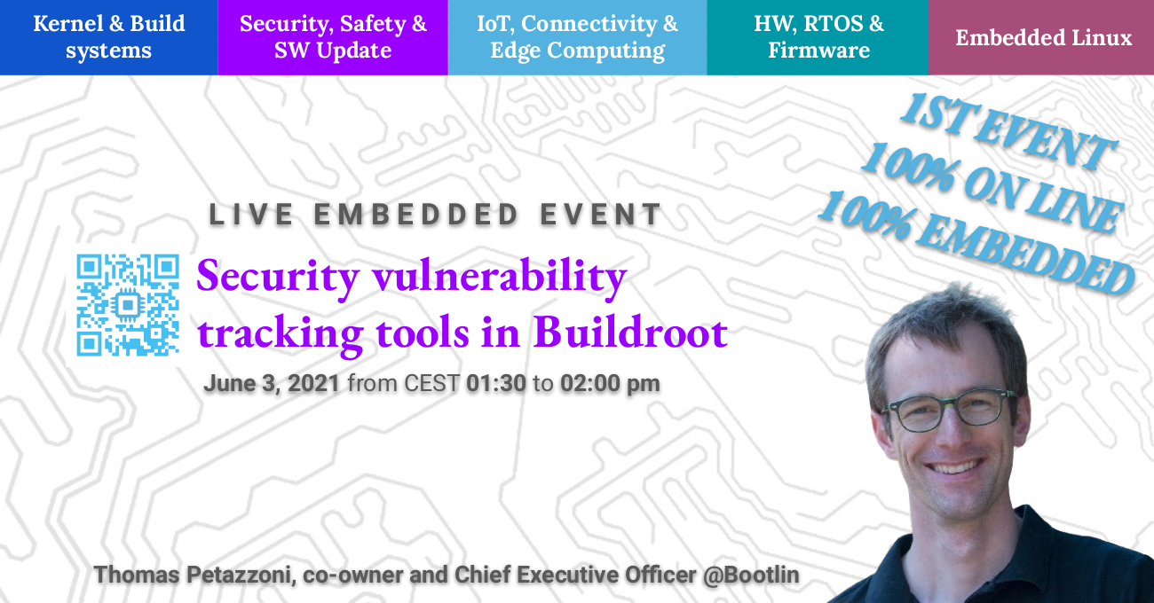
Security vulnerability tracking tools in Buildroot, Thomas Petazzoni
Buildroot is a popular and easy to use embedded Linux build system. With the increasing concern around security vulnerabilities affecting embedded systems, and the need to keep them updated, Buildroot has been extended with new tooling for security vulnerability tracking. This tooling allows to monitor the CVEs that affect the packages present in Buildroot. In this talk, we will introduce the principle of CVEs and CPEs, present the tools now available in Buildroot to help keep track of the security vulnerabilities, show how they can be used for a project and identify the current limitations of this tooling.
Talk given by Thomas Petazzoni, at 1:30 PM CEST on June 3rd, 2021.
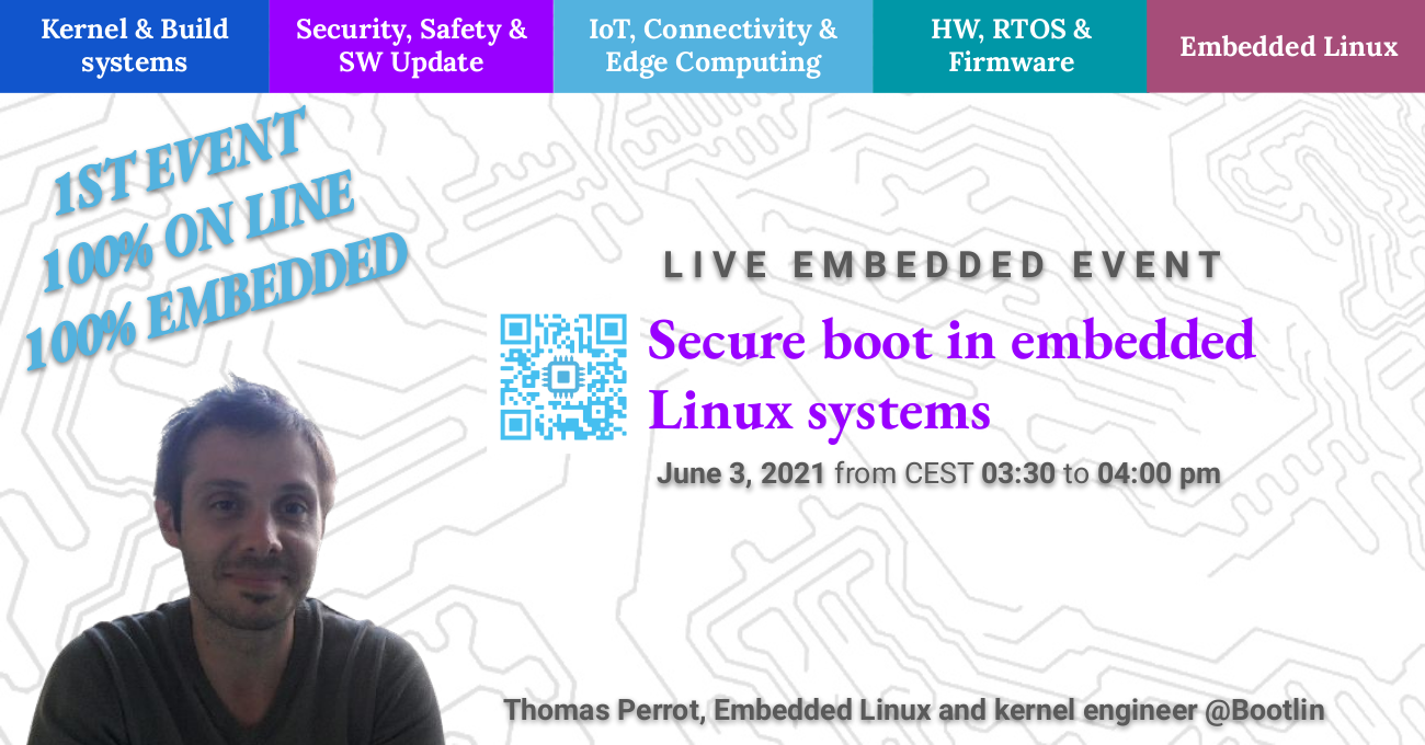
Secure boot in embedded Linux systems, Thomas Perrot
Secure boot is a integrity mechanism, based on signature verification, that allows to detect software corruption or malicious code, during the boot process. Implementing secure boot is not always obvious, as it requires multiple stages of verification, at the bootloader, Linux kernel and root filesystem level, as well as integration into the build system, CI infrastructure, firmware upgrade mechanism, and more. Based on a recent experience to bring secure boot on an NXP i.MX8 platform, Thomas will present how to implement the chain of trust from the SoC ROM code to the root filesystem, as well as other considerations related to the implementation of secure boot. While the presentation will use the i.MX8 as an example, most of the discussion will apply to other platforms as well.
Talk given by Thomas Perrot, at 3:30 PM CEST on June 3rd, 2021.
Device Tree overlays and U-boot extension board management, Köry Maincent
In this talk, we will start by introducing the mechanism of Device Tree Overlays, which are a way of extending the Device Tree itself to describe additional hardware. We will show how Device Tree Overlays are written, compiled, and applied to a base Device Tree, and what is the status of Device Tree Overlays support in U-Boot and Linux. We will take the example of the BeagleBoard.org project, showing how Device Tree overlays are used to make CAPE extension boards compatible with different boards. Finally, we will describe our proposal, already submitted to the community, to add an extension board management facility to U-Boot, which automatically detects, loads and applies the appropriate Device Tree Overlays depending on the extension boards that are detected.
Talk given by Köry Maincent, at 1:30 PM CEST on June 3rd, 2021.
Since March 1st, 2021, we’re happy to have an additional engineer, Hervé Codina, in our engineering team based in Toulouse, France.
Hervé has 20 years’ experience working in embedded systems, both bare-metal systems and embedded Linux systems, in a wide range of applications. Hervé has experience working with U-Boot, Barebox, Linux, Buildroot, Yocto, on ARM platforms from various silicon vendors. Hervé will work within our engineering team to deliver ready-to-use Linux Board Support Packages, port bootloaders and the Linux kernel to new platforms, develop Linux kernel device drivers, implement custom Linux systems with Buildroot or Yocto, and more. His 20 years experience will further increase the expertise that Bootlin provides to its worldwide customers.
Back in December 2020, together with Smile, Logilin and Theoris, Bootlin organized and participated to the first edition of Live Embedded Event, a new 1-day online conference focused on embedded systems topics. Following the success of this first edition, we are now organizing a second edition of Live Embedded Event, which will take place on June 3rd, 2021. Like the previous edition, this event is free.
The call for papers is open, and we are looking for talk proposals on a wide range of topics:
Software update and provisioning
Network connectivity (Long range / Short range)
Edge Computing / ML-AI
Security & Safety
RTOS and Embedded frameworks
Firmware, BSP and Bootloader
Internet Of Things / Cyber Physical Systems
Hardware: system-on-chips, interfaces, FPGA, open hardware
Linux kernel
Build systems: Yocto, OpenWrt, Buildroot
Development process, methods and tools
Embedded Linux
Real time
Two talk formats are proposed: 45 minutes talk + 15 minutes of questions, or 25 minutes talk + 5 minutes of questions. If you want to get a feeling of the talks that were accepted for the first edition, look at the Youtube channel of the event.
We look forward to your proposals for Live Embedded Event #2, and of course, to your participation!
Linux 5.11 was released quite some time ago now, but it’s never too late to have a look at Bootlin contributions to this release. As usual, we recommend reading the LWN articles on the 5.11 merge window: part 1 and part2. Also of interest is the Kernelnewbies page for 5.11.
Here are the main highlights of our contributions:
Alexandre Belloni, as the maintainer of the RTC subsystem, continued making numerous improvements and fixes to RTC drivers
On the support for Microchip ARM platforms, Alexandre Belloni switched the PWM atmel-tcb driver to a new Device Tree binding and added SAMA5D2 support, he did some improvements to the IIO driver for the Microchip ADC, and continued to remove platform_data support from Microchip drivers as all platforms are now converted to the Device Tree.
Alexandre Belloni contributed a new Simple Audio Mux driver for the ALSA subsystem, which can be used to control simple audio multiplexers driven using GPIOs, that allows to select which of their input line is connected to the output line.
Grégory Clement added support for several new MIPS platforms from Microchip: Luton, Serval and Jaguar2. All those platforms include a MIPS core, a few peripherals and more importantly an Ethernet switch. For now the support only includes the base platform support, but we are working on the switchdev driver for the Ethernet switch.
Miquèl Raynal, maintainer of the NAND subsystem and co-maintainer of the MTD subsystem, contributed numerous changes to the ECC support in the MTD subsystem, making it more generic so that it can be used not just for parallel NAND flashes, but also SPI NAND flashes. For more details, see the talk from Miquèl Raynal on this topic.
In addition to those 95 patches that we authored and contributed, several Bootlin engineers being maintainers of different subsystems of the Linux kernel reviewed and merged patches from other contributors:
Miquèl Raynal, as the NAND maintainer and MTD co-maintainer, reviewed and merged 67 patches from other contributors
Alexandre Belloni, as the RTC, I3C and Microchip ARM/MIPS platforms maintainer, reviewed and merged 47 patches from other contributors
Grégory Clement, as the Marvell EBU platform co-maintainer, reviewed and merged 33 patches from other contributors
Here is the detailed list of our contributions to Linux 5.11:
We are happy to announce that Bootlin (formerly Free Electrons) has been acquired by two of its employees, Thomas Petazzoni and Alexandre Belloni.
Bootlin was founded in 2004 by Michael Opdenacker, with the goal of promoting the use of Linux and Free Software in embedded systems worldwide.
Thomas Petazzoni joined Bootlin in 2008, as the first employee. Thomas expanded the company offering by starting an engineering services activity, contributed to the growth of the company and took a CTO position. Thomas has a strong technical, open-source and embedded Linux background: he is the co-maintainer of the Buildroot project, has contributed to the Linux kernel, spoke at multiple international conferences and is the member of several embedded Linux conferences program committees. As Bootlin CTO, Thomas has been in charge of the complete engineering services activity: communication, sales, customer interaction, project management, scheduling and review.
Alexandre Belloni joined Bootlin in 2013, as an embedded Linux engineer. Alexandre has a deep open-source and technical background as well: he is the maintainer of multiple subsystems in the Linux kernel to which he has made significant contributions, and is an expert of the Yocto Project. He has been working closely with Thomas for many years in expanding and managing the engineering services activity.
As part of this acquisition, Thomas Petazzoni will become Bootlin’s CEO, while Alexandre Belloni will take the role of Bootlin’s COO. Michael Opdenacker will stay within Bootlin as an embedded Linux engineer and trainer.
“This acquisition is a logical continuation of my involvement in Bootlin and in the broader embedded Linux community” said Bootlin’s CEO Thomas Petazzoni, who added “I am proud to be leading the excellent engineering team at Bootlin, who will continue to offer the same training and engineering expertise to its customers worldwide”.
Alexandre Belloni, Bootlin’s COO, continued: “with two owners having both a strong technical background and a deep involvement in the open-source community, we intend to continue driving Bootlin with the same core values: technical excellence, open-source contribution and knowledge sharing”
Michael Opdenacker, Bootlin’s founder and former CEO, concluded: “Maria Llavata and I, after more than ten years of dedication to Bootlin’s customers and to the worldwide community of embedded Linux users and developers, are really happy to hand over the baton to Alexandre and Thomas, who have all the energy and enthusiasm needed to continue, expand and renew this beautiful adventure. I believe that Bootlin still has many new things to offer to the world, the fact that I am still on board is a proof of our trust in its new leadership.”
As we announced back in January, we have offered in partnership with ST on February 9 a free webinar titled Device Tree 101, which gives a detailed introduction to the Device Tree, an important mechanism used in the embedded Linux ecosystem to describe hardware platforms. We were happy to see the interest around this topic and webinar.
Bootlin has always shared freely and openly all its technical contents, including our training materials, and this webinar is no exception. We are therefore sharing the slides and video recording of both sessions of this webinar:
Thanks to everyone who participated and thanks to ST for the support in organizing this event! Do not hesitate to share and/or like our video, and to suggest us other topics that would be useful to cover in future webinars!
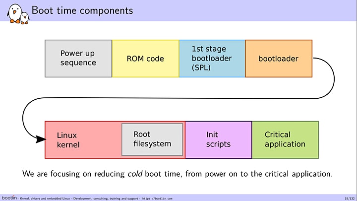
For many embedded products, the issue of how much time it takes from power-on to the application being fully usable by the end-user is an important challenge. Bootlin has been providing its expertise and experience in this area to its customers for many years through numerous boot time optimization projects, and we have shared this knowledge through a number of talks at several conferences over the past years.
We are now happy to announce that we have a new training course Embedded Linux boot time optimization, open for public registration. This training course was already given to selected Bootlin customers and is now available for everyone.
The training course will be lead by Michael Opdenacker, Bootlin’s founder, and author of several publications on the topic of boot time optimization. The course is organized over 4 sessions of 4 hours, with a significant fraction of time spent on practical demonstrations showing on a real-life example the techniques to measure and reduce the boot time of an embedded Linux system.
Our first course open for public registration will take place from April 6th to April 9th, 2021, from 14:00 to 18:00 UTC+2 (Paris time) on each day. The session cost is 519 EUR if you take advantage of the early bird price available until March 9th. Otherwise, the regular rate is 619 EUR. You can register now for this course on Eventbrite.
Also, if you’re interested in organizing a dedicated session for your company, do not hesitate to contact us.


 Since March 1st, 2021, we’re happy to have an additional engineer,