After several months, it’s time to resume our series of blog posts about building a Linux system for the STM32MP1 platform. After showing how to build a minimal Linux system for the STM32MP157 platform, how to connect and use an I2C based pressure/temperature/humidity sensor and how to integrate Qt5 in our system, how to set up a development environment to write our own Qt5 application and how to develop a Qt5 application, we will now cover the topic of factory flashing.
List of articles in this series:
- Building a Linux system for the STM32MP1: basic system
- Building a Linux system for the STM32MP1: connecting an I2C sensor
- Building a Linux system for the STM32MP1: enabling Qt5 for graphical applications
- Building a Linux system for the STM32MP1: setting up a Qt5 application development environment
- Building a Linux system for the STM32MP1: developing a Qt5 graphical application
- Building a Linux system for the STM32MP1: implementing factory flashing
- Building a Linux system for the STM32MP1: remote firmware updates
What is factory flashing ?
So far, we have used a microSD card as storage for the Linux system running on the STM32MP1 platform. Since this media is removable, we can easily switch the microSD card back and forth between the STM32MP1 platform and our development workstation, which is nice during development and debugging.
However, an actual product will most likely use some form of non-removable persistent storage, typically an eMMC or a NAND flash. While not available on the STM32MP1-DK1 board probably for cost reasons, these storage devices are very common in most embedded systems. For example, the STM32MP157A-EV1 board provides three non-removable persistent storage devices: a 4 GB eMMC, a 1 GB NAND flash, and a 64 MB QSPI NOR flash.
When such storage devices are shipped by their manufacturer, they are typically empty. Therefore, as part of the manufacturing process of your embedded systems, you will have to load the relevant storage device with your Linux system, applications and data, so that the embedded system is fully operational: this is the process referred to as factory flashing in this blog post.
If you are doing a very high volume product, you can ask your eMMC or NAND flash vendor to pre-load a system image on the storage before it is shipped to you and assembled on your board. However, many companies do products with volumes that are not large enough to make such a strategy possible: in this case, you really receive an empty storage device, and have to flash it.
A first possibility to flash the non-removable storage is to use a removable storage device, boot a Linux system on the device, and use it to flash the non-removable storage. This can definitely be a possible option in some situations, but it is not always possible (if there’s no removable storage device interface at all) or not always practical.
However, most system-on-chips, including the STM32MP1 include some ROM code that the processor executes at boot time, even before it loads the first stage bootloader. This ROM code is primarly responsible for loading the first stage bootloader into memory, but it also very often offers a communication channel with the outside world, which can be used to gain control of a platform that has nothing at all on its storage. This communication channel is typically over USB or UART, and most often uses a custom, vendor-specific protocol, which is understood by vendor-specific tools. This protocol generally allows to send some code to the target and get it executed, which is sufficient to be able to reflash the target device.
Here are a few examples with system-on-chips from various vendors:
- The ROM code of the NXP i.MX processors implements a USB-based protocol, which can be interfaced either using the NXP-provided mfgtools, or using the community-developed imx_usb_loader. The latter was presented in one of our earlier blog posts about i.MX6 factory flashing.
- The ROM code of Microchip SAMA5 processors implements a USB-based protocol, which can be interfaced using a tool called SAM-BA
- The ROM code of Rockchip processors implements a USB-based protocol, which can be interfaced either using a Rockchip-specific tool called rkdeveloptool
- The ROM code of the ST STM32MP15 processors also implement a USB-based protocol, which can be interfaced using the STM32 Cube Programmer
Obviously, in this blog post, we are going to use the latter, STM32 Cube Programmer, to flash our STM32MP1 platform. Since the DK2 board only has a removable device, we will use the tool to flash the SD card, but the process and logic would be the same for any other (non-removable) storage device.
Getting and installing STM32 Cube Programmer
While ST generally has very good upstream and open-source support for its products, the STM32 Cube Programmer unfortunately doesn’t follow this strategy: you need to be registered on the ST web site to download it, and its source code is not available. Due to this registration process, we for example cannot create a Buildroot package that would automatically download and install this tool for you.
So, follow the process to create an account on the ST web site, and then go to the STM32 Cube Programmer page. At the time of this writing, the latest version is 2.2.1, but according this Wiki page, this version doesn’t work for the STM32MP1 platform. Instead, select to download the 2.2.0 version, which is known to work. You will then download a file called en.stm32cubeprog.zip (it doesn’t have the version in its name, which isn’t great) weighting 187 MB, and which has the SHA256 hash 91107b4d605d126f5c32977247d7419d42abb2655848d2d1a16d52f5f7633d2d.
Extract this ZIP file somewhere in your system, and then run the SetupSTM32CubeProgrammer-2.2.0.linux executable:
$ ./SetupSTM32CubeProgrammer-2.2.0.linux
Got through the installation steps. On our system, we customized the installation path to be just $HOME/stm32cube, and the remainder of this blog post will assume this is where you installed the STM32 Cube Programmer.
In this blog post, we are only going to use the command line interface (CLI) of STM32 Cube Programmer, so just make sure you can run the corresponding tool:
$ ~/stm32cube/bin/STM32_Programmer_CLI
      -------------------------------------------------------------------
                        STM32CubeProgrammer v2.2.0
      -------------------------------------------------------------------


Usage :
STM32_Programmer_CLI.exe [command_1] [Arguments_1][[command_2] [Arguments_2]...]
[...]
Testing the communication with the board
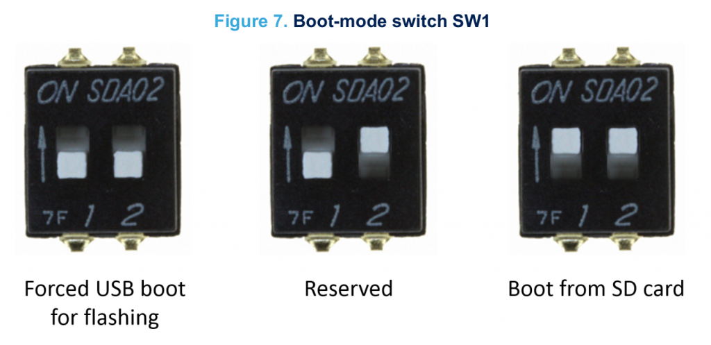
On the back of the board, there is a two-way DIP switch labeled SW1, which is used to configure the boot mode. When both are “ON”, the board boots from the SD card. When both are “OFF”, the board enters the “USB boot for flashing mode”, which is what we are going to use. So switch both switches to OFF, and reset the board.
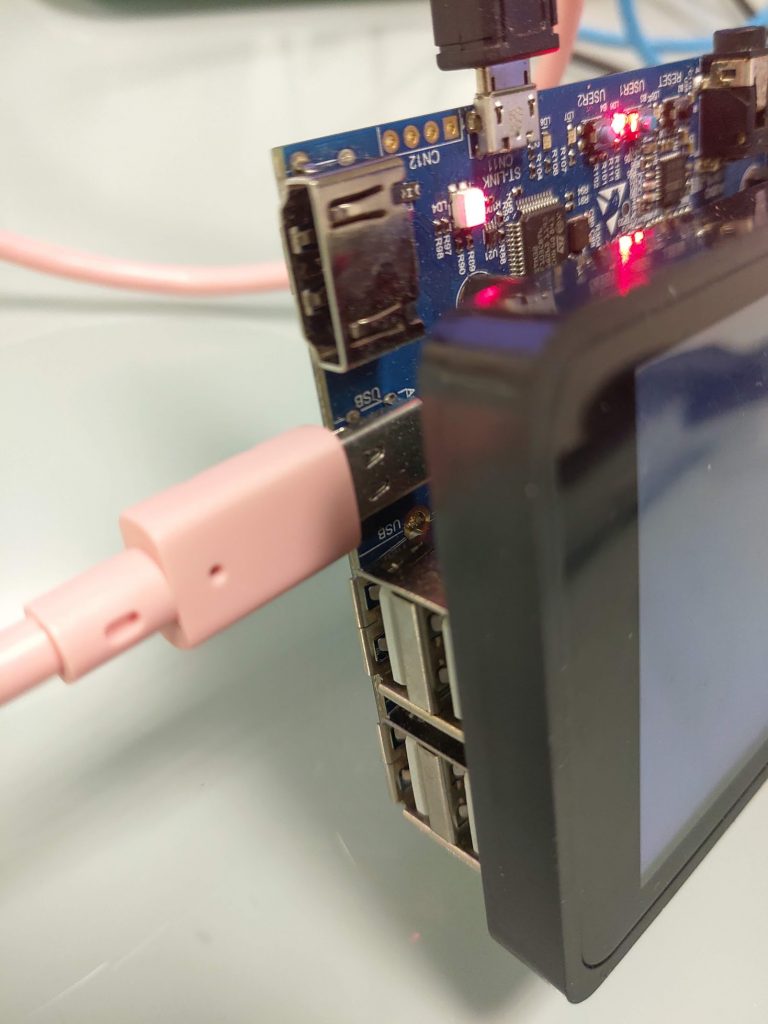
Plug an additional USB-C cable from the board CN7 connector (which is located between the HDMI port and the 4 USB host ports).
Then, reset the board. If you run lsusb on your Linux workstation, you should see a new device:
Bus 003 Device 011: ID 0483:df11 STMicroelectronics STM Device in DFU Mode
Then, you can ask STM32_Programmer_CLI to list the devices it sees over USB. This needs root permissions (unless appropriate udev rules are created):
$ sudo ~/stm32cube/bin/STM32_Programmer_CLI -l usb
      -------------------------------------------------------------------
                        STM32CubeProgrammer v2.2.0
      -------------------------------------------------------------------

=====  DFU Interface   =====

Total number of available STM32 device in DFU mode: 1

  Device Index           : USB1
  USB Bus Number         : 003
  USB Address Number     : 003
  Product ID             : DFU in HS Mode @Device ID /0x500, @Revision ID /0x0000
  Serial number          : 004200343338510534383330
  Firmware version       : 0x0110
  Device ID              : 0x0500
Good, the STM32CubeProgrammer tool is seeing our board, and we see that the Device Index is USB1. Keep that in mind for the next steps.
Change the Linux system boot chain
STM32CubeProgrammer works by sending a U-Boot bootloader over USB, and then talking to this U-Boot to make it erase the MMC or NAND flash, and make it write some data to those storage devices. However, for some reason, STM32CubeProgrammer doesn’t work with the boot flow we have used so far, which uses the U-Boot SPL as the first-stage bootloader, and U-Boot itself as the second stage bootloader. It only works when the first stage bootloader is the Arm Trusted Firmware, also called TF-A. You can get more details about the different possible boot chains on STM32MP1 on this Wiki page.
Due to this constraint, we are going to switch our Buildroot configuration to use TF-A instead of U-Boot SPL as the first stage bootloader.
First of all, we need to backport two Buildroot commits, which did not exist in the Buildroot 2019.02 we are using, but have been integrated later. The first commit, 9dbc934217e170578d4cbfdf524bc1b3988d0b9e allows to build TF-A for ARM 32-bit platforms, while the second commit, e4d276c357fdf9f19f99f826cab63f373687f902 allows to provide a custom name for the TF-A image name.
In Buildroot, do:
$ git cherry-pick 9dbc934217e170578d4cbfdf524bc1b3988d0b9e
$ git cherry-pick e4d276c357fdf9f19f99f826cab63f373687f902
The second one will cause some minor conflict in boot/arm-trusted-firmware/Config.in. Resolve the conflict by removing the BR2_TARGET_ARM_TRUSTED_FIRMWARE_DEBUG option from this file, remove the conflict markers, then run:
git add boot/arm-trusted-firmware/Config.in
git commit
If you’re not sure about this, you can check our 2019.02/stm32mp157-dk-blog-6 branch on Github, which has these changes already integrated.
Once done, we can run make menuconfig and start modifying the Buildroot configuration. Here are the changes that we need:
- In the Bootloaders menu, enable ARM Trusted Firmware (ATF), and then:
- Set ATF Version to
Custom Git repository - Set URL of custom repository to
https://github.com/STMicroelectronics/arm-trusted-firmware.git - Set Custom repository version to
v2.0-stm32mp-r2 - Set ATF platform to
stm32mp1 - Set Additional ATF build variables to
DTB_FILE_NAME=stm32mp157c-dk2.dtb AARCH32_SP=sp_min. TheDTB_FILE_NAMEselects the correct Device Tree file for the DK2 board, while theAARCH32_SPindicates that we are using the “minimal” secure payload, and not a complete Trusted Execution Environment such as OP-TEE. - Set Binary boot images to
*.stm32. This makes sure the final image gets copied tooutput/images.
- Set ATF Version to
- Still in the Bootloaders menu, inside the U-Boot option, make the following changes:
- Change Board defconfig to
stm32mp15_trusted. This is the most important change, which makes U-Boot build only the second stage, and in a format that gets loaded by TF-A as the first stage. - In U-Boot binary format, disable
u-boot.img, and instead enableCustom (specify below)and indicateu-boot.stm32as the value for U-Boot binary format: custom names. - Disable the Install U-Boot SPL binary image option.
- Change Board defconfig to
Overall, the diff of the changes in the configuration looks like this:
@@ -30,16 +30,22 @@ BR2_TARGET_ROOTFS_EXT2=y
 BR2_TARGET_ROOTFS_EXT2_4=y
 BR2_TARGET_ROOTFS_EXT2_SIZE="120M"
 # BR2_TARGET_ROOTFS_TAR is not set
+BR2_TARGET_ARM_TRUSTED_FIRMWARE=y
+BR2_TARGET_ARM_TRUSTED_FIRMWARE_CUSTOM_GIT=y
+BR2_TARGET_ARM_TRUSTED_FIRMWARE_CUSTOM_REPO_URL="https://github.com/STMicroelectronics/arm-trusted-firmware.git"
+BR2_TARGET_ARM_TRUSTED_FIRMWARE_CUSTOM_REPO_VERSION="69cc28c5a1b877cf67def7f94dece087f3917b1c"
+BR2_TARGET_ARM_TRUSTED_FIRMWARE_PLATFORM="stm32mp1"
+BR2_TARGET_ARM_TRUSTED_FIRMWARE_ADDITIONAL_VARIABLES="DTB_FILE_NAME=stm32mp157c-dk2.dtb AARCH32_SP=sp_min"
+BR2_TARGET_ARM_TRUSTED_FIRMWARE_IMAGES="*.stm32"
 BR2_TARGET_UBOOT=y
 BR2_TARGET_UBOOT_BUILD_SYSTEM_KCONFIG=y
 BR2_TARGET_UBOOT_CUSTOM_GIT=y
 BR2_TARGET_UBOOT_CUSTOM_REPO_URL="https://github.com/STMicroelectronics/u-boot.git"
 BR2_TARGET_UBOOT_CUSTOM_REPO_VERSION="v2018.11-stm32mp-r2.1"
-BR2_TARGET_UBOOT_BOARD_DEFCONFIG="stm32mp15_basic"
+BR2_TARGET_UBOOT_BOARD_DEFCONFIG="stm32mp15_trusted"
 BR2_TARGET_UBOOT_CONFIG_FRAGMENT_FILES="board/stmicroelectronics/stm32mp157-dk/uboot-fragment.config"
 # BR2_TARGET_UBOOT_FORMAT_BIN is not set
-BR2_TARGET_UBOOT_FORMAT_IMG=y
-BR2_TARGET_UBOOT_SPL=y
-BR2_TARGET_UBOOT_SPL_NAME="spl/u-boot-spl.stm32"
+BR2_TARGET_UBOOT_FORMAT_CUSTOM=y
+BR2_TARGET_UBOOT_FORMAT_CUSTOM_NAME="u-boot.stm32"
 BR2_TARGET_UBOOT_CUSTOM_MAKEOPTS="DEVICE_TREE=stm32mp157c-dk2"
 BR2_PACKAGE_HOST_GENIMAGE=y
Before we can restart the build, we need to adjust the genimage.cfg file that describes the layout of the SD card. Indeed, the file name of the first stage bootloader is now tf-a-stm32mp157c-dk2.stm32 instead of u-boot-spl.stm32 and the file name of the second stage bootloader is now u-boot.stm32 instead of u-boot.img. All in all, your genimage.cfg file in board/stmicroelectronics/stm32mp157-dk/genimage.cfg should now look like this:
image sdcard.img {
	hdimage {
		gpt = "true"
	}

	partition fsbl1 {
		image = "tf-a-stm32mp157c-dk2.stm32"
	}

	partition fsbl2 {
		image = "tf-a-stm32mp157c-dk2.stm32"
	}

	partition ssbl {
		image = "u-boot.stm32"
	}

	partition rootfs {
		image = "rootfs.ext4"
		partition-type = 0x83
		bootable = "yes"
		size = 256M
	}
}
With this in place, it’s time to restart the build. You can do a complete rebuild with make clean all, or you can just clean up U-Boot, and restart the build:
$ make uboot-dirclean
$ make
You should now have in output/images the new TF-A image tf-a-stm32mp157c-dk2.stm32 and the new U-Boot image u-boot.stm32. Of course the sdcard.img file has been updated.
Rather than updating our SD card on our workstation, we’ll directly use the STM32CubeProgrammer tool to do that, in the next section.
Flashing the board
The STM32CubeProgrammer tool takes as input a flash layout file, which has a .tsv extension. The format of this file is extensively documented on this Wiki page. It is essentially a text file that says what should be flashed in each partition.
In our case, we are going to simply flash the entire sdcard.img instead of flashing partition by partition. To achieve this, we are going to use the RawImage image type, also described on the Wiki page.
Let’s create a file board/stmicroelectronics/stm32mp157-dk/flash.tsv, with the following contents:
#Opt	Id	Name	Type	IP	Offset	Binary
-	0x01	fsbl1-boot	Binary	none	0x0	tf-a-stm32mp157c-dk2.stm32
-	0x03	ssbl-boot	Binary	none	0x0	u-boot.stm32
P	0x10	sdcard	RawImage	mmc0		0x0	sdcard.img
The first line is a comment, just to help remember what each field is about. The second and third lines tell STM32CubeProgrammer which bootloader images should be used as part of the flashing process. Finally, the last line says we want to flash sdcard.img as a raw image on the mmc0 device.
Then, go do output/images, and run STM32CubeProgrammer. We use the -c port=usb1 argument, because our board was detected as device USB1 when we enumerated all detected devices using the -l usb previously.
$ cd output/images/
$ sudo ~/stm32cube/bin/STM32_Programmer_CLI -c port=usb1 -w ../../board/stmicroelectronics/stm32mp157-dk/flash.tsv
The output will look like this:
      -------------------------------------------------------------------
                        STM32CubeProgrammer v2.2.0
      -------------------------------------------------------------------


USB speed   : High Speed (480MBit/s)
Manuf. ID   : STMicroelectronics
Product ID  : DFU in HS Mode @Device ID /0x500, @Revision ID /0x0000
SN          : 004200343338510534383330
FW version  : 0x0110
Device ID   : 0x0500
Device name : STM32MPxxx
Device type : MPU
Device CPU  : Cortex-A7


Start Embedded Flashing service


Memory Programming ...
Opening and parsing file: tf-a-stm32mp157c-dk2.stm32
  File          : tf-a-stm32mp157c-dk2.stm32
  Size          : 237161 Bytes
  Partition ID  : 0x01

Download in Progress:
[==================================================] 100%

File download complete
Time elapsed during download operation: 00:00:00.444

RUNNING Program ...
  PartID:      :0x01
Start operation done successfully at partition 0x01

Flashlayout Programming ...
[==================================================] 100%
Running Flashlayout Partition ...
Flashlayout partition started successfully


Memory Programming ...
Opening and parsing file: u-boot.stm32
  File          : u-boot.stm32
  Size          : 748042 Bytes
  Partition ID  : 0x03

Download in Progress:
[==================================================] 100%

File download complete
Time elapsed during download operation: 00:00:00.791

RUNNING Program ...
  PartID:      :0x03

reconnecting the device ...

USB speed   : High Speed (480MBit/s)
Manuf. ID   : STMicroelectronics
Product ID  : USB download gadget@Device ID /0x500, @Revision ID /0x0000
SN          : 004200343338510534383330
FW version  : 0x0110
Device ID   : 0x0500
Start operation done successfully at partition 0x03


Memory Programming ...
Opening and parsing file: sdcard.img
  File          : sdcard.img
  Size          : 539002368 Bytes
  Partition ID  : 0x10

Download in Progress:
[==================================================] 100%

File download complete
Time elapsed during download operation: 00:04:31.583

RUNNING Program ...
  PartID:      :0x10
Start operation done successfully at partition 0x10
Flashing service completed successfully
Finally, we can toggle back the SW1 DIP switches to their ON position, to boot again from SD card, and hit the reset button. The board should boot, but this time with our new image, which uses TF-A instead of U-Boot SPL, so the first lines of the boot process should look like this:
NOTICE:  CPU: STM32MP157CAC Rev.B
NOTICE:  Model: STMicroelectronics STM32MP157C-DK2 Discovery Board
NOTICE:  Board: MB1272 Var2 Rev.C-01
NOTICE:  BL2: v2.0-r2.0(release):
NOTICE:  BL2: Built : 16:10:53, Jan  7 2020
NOTICE:  BL2: Booting BL32
NOTICE:  SP_MIN: v2.0-r2.0(release):
NOTICE:  SP_MIN: Built : 16:10:53, Jan  7 2020

U-Boot 2018.11-stm32mp-r2.1 (Jan 07 2020 - 16:13:55 +0100)
Conclusion
In this article, we have discussed the concept of factory flashing, understood better the different boot chains available for the STM32MP1, switched to a boot chain using TF-A, and presented how to use STM32CubeProgrammer to reflash the entire SD card.
As usual, we have a branch on Github with the Buildroot changes corresponding to this blog post, see the branch 2019.02/stm32mp157-dk-blog-6.
Stay tuned for the next article in this series of blog post, in which we will cover the topic of Over-The-Air firmware update.