Updated Buildroot support for STM32MP1 platforms, ST BSP v5.0

We continue the support of the buildroot-external-st project as presented in our first announce, which is an extension of the Buildroot build system with ready-to-use configurations for the STMicroelectronics STM32MP1 platforms. We already published several updates of this support, with the LTS 2022.02 and version 4.0 of ST BSP version update and the LTS 2022.02.7 and version 4.1 of ST BSP version update.

More specifically, this project is a BR2_EXTERNAL repository for Buildroot, with a number of defconfigs that allow to quickly build embedded Linux systems for the STM32MP1 Discovery Kit platforms. It’s a great way to get started with Buildroot on those platforms.

Today, we are happy to announce an updated version of this project, published under the branch st/2023.02.10 at https://github.com/bootlin/buildroot-external-st. This new version brings a number of additional features:

Continue reading “Updated Buildroot support for STM32MP1 platforms, ST BSP v5.0”

Boot time: choose your kernel loading address carefully

When the compressed and uncompressed kernel images overlap

At least on ARM32, there seems to be many working addresses where the compressed kernel can be loaded in RAM. For example, one can load the compressed kernel at offset 0x1000000 (16 MB) from the start of RAM, and the Device Tree Blog (DTB) at offset 0x2000000 (32 MB). Whatever this loading address, the kernel is then decompressed at offset 0x8000 from the start of RAM, as explained this the famous How the ARM32 Linux kernel decompresses article from Linus Walleij.

There is a potential issue with the loading address of the compressed kernel, as explained in the article too. If the compressed kernel is loaded too close to the beginning of RAM, where the kernel must be decompressed, there will be an overlap between the two. The decompressed kernel will overwrite the compressed one, potentially breaking the decompression process.

Overlapping compressed and decompressed kernel

As you see in the above diagram, when this happens, the bootstrap code in the compressed kernel will first copy the compressed image to a location that’s far enough to guarantee that the decompressed kernel won’t overlap it. However, this extra step in the boot process has a cost.

Measuring boot time impact

In the context of updating our materials for our upcoming Embedded Linux Boot Time Optimization course in June, we measured this additional time on the STM32MP157A-DK1 Discovery Kit from STMicroelectronics, with a dual-core ARM Cortex-A7 CPU running at 650 MHz.

Initially, in our Embedded Linux System Development course, we were booting the DK1 board as follows:

ext4load mmc 0:4 0xc0000000 zImage; ext4load mmc 0:4 0xc4000000 dtb; bootz 0xc0000000 - 0xc4000000

0xc0000000 is exactly the beginning of RAM! We are therefore in the overlap situation.

We used grabserial from Tim Bird to measure the time between Starting kernel in U-Boot and when the compressed kernel starts executing (Booting Linux on physical CPU 0x0):

...
[4.451996 0.000124] Starting kernel ...
[0.001838 0.001838] 
[2.439980 2.438142] [    0.000000] Booting Linux on physical CPU 0x0
...

On a series of 5 identical tests, we obtained an average time of 2,440 ms, with a standard deviation of 0.4 ms.

Then, we measured the optimum case, in which the compressed kernel is loaded far enough from the beginning of RAM so that no overlap is possible:

No overlap between compressed and decompressed kernel

Here we chose to load the kernel at 0xc2000000:

ext4load mmc 0:4 0xc2000000 zImage; ext4load mmc 0:4 0xc4000000 dtb; bootz 0xc2000000 - 0xc4000000

On a series of 5 identical tests, we obtained an average time of 2,333 ms, with a standard deviation of 0.7 ms.

The new average is 107 ms smaller, which you are likely to consider as a worthy reduction, if you have experience with boot time reduction projects.

What to remember

In your embedded projects, if you are using a compressed kernel, make sure it is loaded far enough from the beginning of RAM, leaving enough space for the decompressed kernel to fit in between. Otherwise, your system will still be able to boot, but depending on the speed of your CPU and storage, it will be slower, from a few tens to a few hundreds of milliseconds.

We checked the How to optimize the boot time page on the STM32 wiki, and it recommends optimum loading addresses: 0xc2000000 for the kernel and 0xc4000000 for the device tree. This way, the upper limit for the decompressed kernel is 32 MB, which is more than enough.

If you are directly using an uncompressed kernel, which is more rare, you should also make sure that it is loaded at an optimum location, so that there is no need to move it before starting it.

Updated Buildroot support for STM32MP1 platforms, ST BSP v4.1

Back in December 2021, we announced the buildroot-external-st project, which is an extension of the Buildroot build system with ready-to-use configurations for the STMicroelectronics STM32MP1 platforms. Later on, in July 2022, we updated it to the lastest Buildroot LTS 2022.02 and version 4.0 of ST BSP version.

More specifically, this project is a BR2_EXTERNAL repository for Buildroot, with a number of defconfigs that allow to quickly build embedded Linux systems for the STM32MP1 Discovery Kit platforms. It’s a great way to get started with Buildroot on those platforms.

Today, we are happy to announce an updated version of this project, published under the branch st/2022.02.7 at https://github.com/bootlin/buildroot-external-st. This new version brings the following changes:

Continue reading “Updated Buildroot support for STM32MP1 platforms, ST BSP v4.1”

Updated Buildroot support for STM32MP1 platforms

Back in December 2021, we had announced the buildroot-external-st project, which is an extension of the Buildroot build system with ready-to-use configurations for the STMicroelectronics STM32MP1 platforms.

More specifically, this project is a BR2_EXTERNAL repository for Buildroot, with a number of defconfigs that allows to quickly build embedded Linux systems for the STM32MP1 Discovery Kit platforms. It’s a great way to get started with Buildroot on those platforms.

Today, we are happy to announce an updated version of this project, published under the branch st/2022.02 at https://github.com/bootlin/buildroot-external-st. This new version brings the following changes:

  • Updated to work with Buildroot 2022.02, the current LTS version of Buildroot
  • Updated to use the 4.0 “ecosystem” from ST, which means we’re using updated BSP components from ST, namely Linux 5.15, U-Boot 2021.10, TF-A 2.6 and OP-TEE 3.16
  • New defconfigs have been added to support all variants of the STM32MP157 Discovery Kits: STM32MP157A-DK1 and STM32MP157D-DK1, as well as STM32MP157C-DK2 and STM32MP157F-DK2.
  • The minimal defconfigs now use OP-TEE as BL32 instead of the minimal monitor provided by TF-A, called SP-MIN
  • The minimal defconfigs now have mdev enabled, to benefit from automatic kernel module loading
  • The demo defconfigs now have the Dropbear SSH server enabled

The document available on the Github page details how to use this work, but here is a quick start in just a few steps:

  1. Retrieve Buildroot itself, a branch containing a few patches on top of upstream 2022.02 is needed
    $ git clone -b st/2022.02 https://github.com/bootlin/buildroot.git
  2. Retrieve buildroot-external-st
    $ git clone -b st/2022.02 https://github.com/bootlin/buildroot-external-st.git
  3. Go into the Buildroot directory
    $ cd buildroot/
  4. Configure Buildroot, for example here the demo configuration for the STM32MP157F-DK2
    $ make BR2_EXTERNAL=../buildroot-external-st st_stm32mp157f_dk2_demo_defconfig
  5. Run the build
    $ make
  6. Flash the resulting SD card image available at output/images/sdcard.img and boot your board!

If you have any question or issue, feel free to use the Github issue tracker to contact us. Bootlin is an ST Authorized Partner, and can provide engineering and training services around embedded Linux on STM32MP1 platforms.

Announcing buildroot-external-st, Buildroot support for STM32MP1 platforms

STM32MP1 Discovery Kit 2Back in 2019, ST released a brand new processor family, the STM32MP1, whose members are currently based on a dual Cortex-A7 to run Linux combined with one Cortex-M4 to run bare-metal applications, together with a wide range of peripherals.

Following the release of this new platform, Bootlin ported its Embedded Linux and Yocto training courses to be available on STM32MP1, and also published a long series of tutorials showing how to use Buildroot to build an embedded Linux system on STM32MP1: part 1, part 2, part 3, part 4, part 5, part 6 and part 7.

We are happy to announce that we have partnered with ST to develop an improved support of Buildroot on STM32MP1, which is materialized by a Buildroot BR2_EXTERNAL available on Github at https://github.com/bootlin/buildroot-external-st. In Buildroot, a BR2_EXTERNAL is an extension of the core Buildroot, with additional configurations and/or packages.

This BR2_EXTERNAL tree is an extension of Buildroot 2021.02, which provides four example Buildroot configuration to easily get started on STM32MP1 platforms:

  • st_stm32mp157a_dk1, building a basic Linux system for the STM32MP1 Discovery Kit 1 platform, with a minimal Linux root filesystem
  • st_stm32mp157c_dk2, building a basic Linux system for the STM32MP1 Discovery Kit 2 platform, with a minimal Linux root filesystem
  • st_stm32mp157a_dk1_demo, building a much more featureful Linux system for the STM32MP1 Discovery Kit 1 platform, with Linux root filesystem that allows to run Qt5 applications with OpenGL acceleration on the HDMI output, that supports audio, demonstrates the usage of the Cortex-M4, uses OP-TEE, and more.
  • st_stm32mp157c_dk2_demo, building a much more featureful Linux system for the STM32MP1 Discovery Kit 2 platform, with Linux root filesystem that allows to run Qt5 applications with OpenGL acceleration on both the integrated DSI display and HDMI output, that supports audio, WiFi and Bluetooth, demonstrates the usage of the Cortex-M4, uses OP-TEE, and more.

This BR2_EXTERNAL is designed to work with Buildroot 2021.02, with only a small set of modifications, which since then have been integrated in upstream Buildroot, ensuring that STM32MP1 users can directly use upstream Buildroot for their projects.

There is extensive documentation on how to use this BR2_EXTERNAL tree as well as how to test the various features of the STM32MP1 platform: using STM32CubeProgrammer, using Device Tree generated from STM32 CubeMX, using the Cortex-M4, testing display support, using Qt5, using WiFi, using Bluetooth, using audio and using OP-TEE. We have also documented the internals of the BR2_EXTERNAL components.

This Buildroot support is using the latest software components from the recently released 3.1 BSP from ST (see release notes), so it is based on Linux 5.10, U-Boot 2020.10, TF-A 2.4 and OP-TEE 3.12. We will keep this BR2_EXTERNAL updated with newer releases of the ST BSP.

If you face any issue while using this Buildroot support for STM32MP1, you can use the issue tracker of the Github project, or use the ST community forums. Bootlin can also provide commercial support on Linux on STM32MP1 platforms, as well as training courses.

Building a Linux system for the STM32MP1: remote firmware updates

After another long break, here is our new article in the series of blog posts about building a Linux system for the STM32MP1 platform. After showing how to build a minimal Linux system for the STM32MP157 platform, how to connect and use an I2C based pressure/temperature/humidity sensor and how to integrate Qt5 in our system, how to set up a development environment to write our own Qt5 application, how to develop a Qt5 application, and how to setup factory flashing, we are now going to discuss the topic of in-field firmware update.

List of articles in this series:

  1. Building a Linux system for the STM32MP1: basic system
  2. Building a Linux system for the STM32MP1: connecting an I2C sensor
  3. Building a Linux system for the STM32MP1: enabling Qt5 for graphical applications
  4. Building a Linux system for the STM32MP1: setting up a Qt5 application development environment
  5. Building a Linux system for the STM32MP1: developing a Qt5 graphical application
  6. Building a Linux system for the STM32MP1: implementing factory flashing
  7. Building a Linux system for the STM32MP1: remote firmware updates

Why remote firmware updates?

The days and age when it was possible to build and flash an embedded system firmware, ship the device and forget it, are long behind us. Systems have gotten more complicated, and we therefore have to fix bugs and security issues after the device has been shipped, and we often want to deploy new features in the field into existing devices. For all those reasons, the ability to remotely update the firmware of embedded devices is now a must-have.

Open-source firmware update tools

There are different possibilities to update your system:

  • If you’re using a binary distribution, use the package manager of this distribution to update individual components
  • Do complete system image updates, at the block-level, replacing the entire system image with an updated one. Three main open-source solutions are available: swupdate, Mender.io and RAUC.
  • Do file-based updates, with solutions such as OSTree.

In this blog post, we are going to show how to set up the swupdate solution.

swupdate is a tool installed on the target that can receive an update image (.swu file), either from a local media or from a remote server, and use it to update various parts of the system. Typically, it will be used to update the Linux kernel and the root filesystem, but it can also be used to update additional partitions, FPGA bitstreams, etc.

swupdate implements two possible update strategies:

  • A dual copy strategy, where the storage has enough space to store two copies of the entire filesystem. This allows to run the system from copy A, update copy B, and reboot it into copy B. The next update will of course update copy A.
  • A single copy strategy, where the upgrade process consists in rebooting into a minimal system that runs entirely from RAM, and that will be responsible for updating the system on storage.

For this blog post, we will implement the dual copy strategy, but the single copy strategy is also supported for systems with tighter storage restrictions.

We are going to setup swupdate step by step: first by triggering updates locally, and then seeing how to trigger updates remotely.

Local usage of swupdate

Add USB storage support

As a first step, in order to transfer the update image to the target, we will use a USB stick. This requires having USB mass storage support in the Linux kernel. So let’s adjust our Linux kernel configuration by running make linux-menuconfig. Within the Linux kernel configuration:

  • Enable the CONFIG_SCSI option. This is a requirement for USB mass storage support
  • Enable the CONFIG_BLK_DEV_SD option, needed for SCSI disk support, which is another requirement for USB mass storage.
  • Enable the CONFIG_USB_STORAGE option.
  • The CONFIG_VFAT_FS option, to support the FAT filesystem, is already enabled.
  • Enable the CONFIG_NLS_CODEPAGE_437 and CONFIG_NLS_ISO8859_1 options, to have the necessary support to decode filenames in the FAT filesystem.

Then, run make linux-update-defconfig to preserve these kernel configurations changes in your kernel configuration file at board/stmicroelectronics/stm32mp157-dk/linux.config.

swupdate setup

In Target packages, System tools, enable swupdate. You can disable the install default website setting since we are not going to use the internal swupdate web server.

Take this opportunity to also enable the gptfdisk tool and its sgdisk sub-option in the Hardware handling submenu. We will need this tool later to update the partition table at the end of the update process.

Now that we have both both USB storage support and the swupdate package enabled, let’s build a new version of our system by running make. Flash the resulting image on your SD card, and boot your target. You should have swupdate available:

# swupdate -h
Swupdate v2018.11.0

Licensed under GPLv2. See source distribution for detailed copyright notices.

swupdate (compiled Mar  4 2020)
Usage swupdate [OPTION]
 -f, --file           : configuration file to use
 -p, --postupdate               : execute post-update command
 -e, --select , : Select software images set and source
                                  Ex.: stable,main
 -i, --image          : Software to be installed
 -l, --loglevel          : logging level
 -L, --syslog                   : enable syslog logger
 -n, --dry-run                  : run SWUpdate without installing the software
 -N, --no-downgrading  : not install a release older as 
 -o, --output      : saves the incoming stream
 -v, --verbose                  : be verbose, set maximum loglevel
     --version                  : print SWUpdate version and exit
 -c, --check                    : check image and exit, use with -i 
 -h, --help                     : print this help and exit
 -w, --webserver [OPTIONS]      : Parameters to be passed to webserver
	mongoose arguments:
	  -l, --listing                  : enable directory listing
	  -p, --port               : server port number  (default: 8080)
	  -r, --document-root      : path to document root directory (default: .)
	  -a, --api-version [1|2]        : set Web protocol API to v1 (legacy) or v2 (default v2)
	  --auth-domain                  : set authentication domain if any (default: none)
	  --global-auth-file             : set authentication file if any (default: none)

Take a USB stick with a FAT filesystem on it, which you can mount:

# mount /dev/sda1 /mnt

If that works, we’re now ready to move on to the next step of actually getting a firmware update image.

Generate the swupdate image

swupdate has its own update image format, and you need to generate an image that complies with this format so that swupdate can use it to upgrade your system. The format is simple: it’s a CPIO archive, which contains one file named sw-description describing the contents of the update image, and one or several additional files that are the images to update.

First, let’s create our sw-description file in board/stmicroelectronics/stm32mp157-dk/sw-description. The tags and properties available are described in the swupdate documentation.

software = {
	version = "0.1.0";
	rootfs = {
		rootfs-1: {
			images: (
			{
				filename = "rootfs.ext4.gz";
				compressed = true;
				device = "/dev/mmcblk0p4";
			});
		}
		rootfs-2: {
			images: (
			{
				filename = "rootfs.ext4.gz";
				compressed = true;
				device = "/dev/mmcblk0p5";
			});
		}
	}
}

This describes a single software component rootfs, which is available as two software collections, to implement the dual copy mechanism. The root filesystem will have one copy in /dev/mmcblk0p4 and another copy in /dev/mmcblk0p5. They will be updated from a compressed image called rootfs.ext4.gz.

Once this sw-description file is written, we can write a small script that generates the swupdate image. We’ll put this script in board/stmicroelectronics/stm32mp157-dk/gen-swupdate-image.sh:

#!/bin/sh

BOARD_DIR=$(dirname $0)

cp ${BOARD_DIR}/sw-description ${BINARIES_DIR}

IMG_FILES="sw-description rootfs.ext4.gz"

pushd ${BINARIES_DIR}
for f in ${IMG_FILES} ; do
	echo ${f}
done | cpio -ovL -H crc > buildroot.swu
popd

It simply copies the sw-description file to BINARIES_DIR (which is output/images), and then creates a buildroot.swu CPIO archive that contains the sw-description and rootfs.ext4.gz files.

Of course, make sure this script has executable permissions.

Then, we need to slightly adjust our Buildroot configuration, so run make menuconfig, and:

  • In System configuration, in the option Custom scripts to run after creating filesystem images, add board/stmicroelectronics/stm32mp157-dk/gen-swupdate-image.sh after the existing value support/scripts/genimage.sh. This will make sure our new script generating the swupdate image is executed as a post-image script, at the end of the build.
  • In Filesystem images, enable the gzip compression method for the ext2/3/4 root filesystem, so that a rootfs.ext4.gz image is generated.

With that in place, we are now able to generate our firmware image, by simply running make in Buildroot. At the end of the build, the output/images/ folder should contain the sw-description and rootfs.ext4.gz files. You can look at the contents of buildroot.swu:

$ cat output/images/buildroot.swu | cpio -it
sw-description
rootfs.ext4.gz
58225 blocks

Partioning scheme and booting logic

We now need to adjust the partitioning scheme of our SD card so that it has two partitions for the root filesystem, one for each copy. This partitioning scheme is defined in board/stmicroelectronics/stm32mp157-dk/genimage.cfg, which we change to:

image sdcard.img {
        hdimage {
                gpt = "true"
        }

        partition fsbl1 {
                image = "tf-a-stm32mp157c-dk2.stm32"
        }

        partition fsbl2 {
                image = "tf-a-stm32mp157c-dk2.stm32"
        }

        partition ssbl {
                image = "u-boot.stm32"
        }

        partition rootfs1 {
                image = "rootfs.ext4"
                partition-type = 0x83
                bootable = "yes"
                size = 256M
        }

        partition rootfs2 {
                partition-type = 0x83
                size = 256M
        }
}

As explained in the first blog post of this series, the /boot/extlinux/extlinux.conf file is read by the bootloader to know how to boot the system. Among other things, this file defines the Linux kernel command line, which contains root=/dev/mmcblk0p4 to tell the kernel where the root filesystem is. But with our dual copy upgrade scheme, the root filesystem will sometimes be on /dev/mmcblk0p4, sometimes on /dev/mmcblk0p5. To achieve that without constantly updating the extlinux.conf file, we will use /dev/mmcblk0p${devplist} instead. devplist is a U-Boot variable that indicates from which partition the extlinux.conf file was read, which turns out to be the partition of our root filesystem. So, your board/stmicroelectronics/stm32mp157-dk/overlay/boot/extlinux/extlinux.conf file should look like this:

label stm32mp15-buildroot
  kernel /boot/zImage
  devicetree /boot/stm32mp157c-dk2.dtb
  append root=/dev/mmcblk0p${devplist} rootwait console=ttySTM0,115200 vt.global_cursor_default=0

For the dual copy strategy to work, we need to tell the bootloader to boot either from the root filesystem in the rootfs1 partition or the rootfs2 partition. This will be done using the bootable flag of each GPT partition, and this is what this script does: it toggles the bootable flag of 4th and 5th partition of the SD card. This way, the partition with the bootable flag will lose it, and the other partition will gain it. Thanks to this, at the next reboot, U-Boot will consider the system located in the other SD card partition. This work will be done by a /etc/swupdate/postupdate.sh script, that you will store in board/stmicroelectronics/stm32mp157-dk/overlay/etc/swupdate/postupdate.sh, which contains:

#!/bin/sh
sgdisk -A 4:toggle:2 -A 5:toggle:2 /dev/mmcblk0
reboot

Make sure this script is executable.

With all these changes in place, let’s restart the Buildroot build by running make. The sdcard.img should contain the new partioning scheme:

$ sgdisk -p output/images/sdcard.img
[...]
Number  Start (sector)    End (sector)  Size       Code  Name
   1              34             497   232.0 KiB   8300  fsbl1
   2             498             961   232.0 KiB   8300  fsbl2
   3             962            2423   731.0 KiB   8300  ssbl
   4            2424          526711   256.0 MiB   8300  rootfs1
   5          526712         1050999   256.0 MiB   8300  rootfs2

Reflash your SD card with the new sdcard.img, and boot this new system. Transfer the buildroot.swu update image to your USB stick.

Testing the firmware update locally

After booting the system, mount the USB stick, which contains the buildroot.swu file:

# mount /dev/sda1 /mnt/
# ls /mnt/
buildroot.swu

Let’s trigger the system upgrade with swupdate:

# swupdate -i /mnt/buildroot.swu -e rootfs,rootfs-2 -p /etc/swupdate/postupdate.sh

Swupdate v2018.11.0

Licensed under GPLv2. See source distribution for detailed copyright notices.

Registered handlers:
	dummy
	raw
	rawfile
software set: rootfs mode: rootfs-2
Software updated successfully
Please reboot the device to start the new software
[INFO ] : SWUPDATE successful ! 
Warning: The kernel is still using the old partition table.
The new table will be used at the next reboot or after you
run partprobe(8) or kpartx(8)
The operation has completed successfully.
# Stopping qt-sensor-demo: OK
Stopping dropbear sshd: OK
Stopping network: OK
Saving random seed... done.
Stopping klogd: OK
Stopping syslogd: OK
umount: devtmpfs busy - remounted read-only
[  761.949576] EXT4-fs (mmcblk0p4): re-mounted. Opts: (null)
The system is going down NOW!
Sent SIGTERM to all processes
Sent SIGKILL to all processes
Requesting system reboot
[  763.965243] reboot: ResNOTICE:  CPU: STM32MP157CAC Rev.B
NOTICE:  Model: STMicroelectronics STM32MP157C-DK2 Discovery Board

The -i option indicates the firmware update file, while the -e option indicates which software component should be updated. Here we update the rootfs in its slot 2, rootfs-2, which is in /dev/mmcblk0p5. The -p option tells to run our post-update script when the update is successful. In the above log, we see that the system is being rebooted right after the update.

At the next boot, you should see:

U-Boot 2018.11-stm32mp-r2.1 (Mar 04 2020 - 15:28:34 +0100)
[...]
mmc0 is current device
Scanning mmc 0:5...
Found /boot/extlinux/extlinux.conf
[...]
append: root=/dev/mmcblk0p5 rootwait console=ttySTM0,115200 vt.global_cursor_default=0

during the U-Boot part. So we see it is loading extlinux.conf from the MMC partition 5, and has properly set root=/dev/mmcblk0p5. So the kernel and Device Tree will be loaded from MMC partition 5, and this partition will also be used by Linux as the root filesystem.

With all this logic, we could now potentially have some script that gets triggered when a USB stick is inserted, mount it, check if an update image is available on the USB stick, and if so, launch swupdate and reboot. This would be perfectly fine for local updates, for example with an operator in charge of doing the update of the device.

However, we can do better, and support over-the-air updates, a topic that we will discuss in the next section.

Over-the-air updates

To support over-the-air updates with swupdate, we will have to:

  1. Install on a server a Web interface that allows the swupdate program to retrieve firmware update files, and the user to trigger the updates.
  2. Run swupdate in daemon mode on the target.

Set up the web server: hawkBit

swupdate is capable of interfacing with a management interface provided by the Eclipse hawkBit project. Using this web interface, one can manage its fleet of embedded devices, and rollout updates to these devices remotely.

hawkBit has plenty of capabilities, and we are here going to set it up in a very minimal way, with no authentication and a very simple configuration.

As suggested in the project getting started page, we’ll use a pre-existing Docker container image to run hawkBit:

sudo docker run -p 8080:8080 hawkbit/hawkbit-update-server:latest \
     --hawkbit.dmf.rabbitmq.enabled=false \
     --hawkbit.server.ddi.security.authentication.anonymous.enabled=true

After a short while, it should show:

2020-03-06 09:15:46.492  ... Started ServerConnector@3728a578{HTTP/1.1,[http/1.1]}{0.0.0.0:8080}
2020-03-06 09:15:46.507  ... Jetty started on port(s) 8080 (http/1.1) with context path '/'
2020-03-06 09:15:46.514  ... Started Start in 21.312 seconds (JVM running for 22.108)

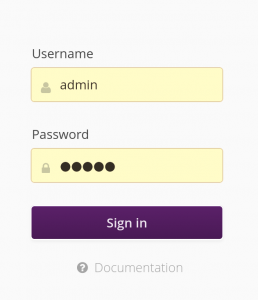
From this point, you can connect with your web browser to http://localhost:8080 to access the hawkBit interface. Login with the admin login and admin password.

hawkBit login

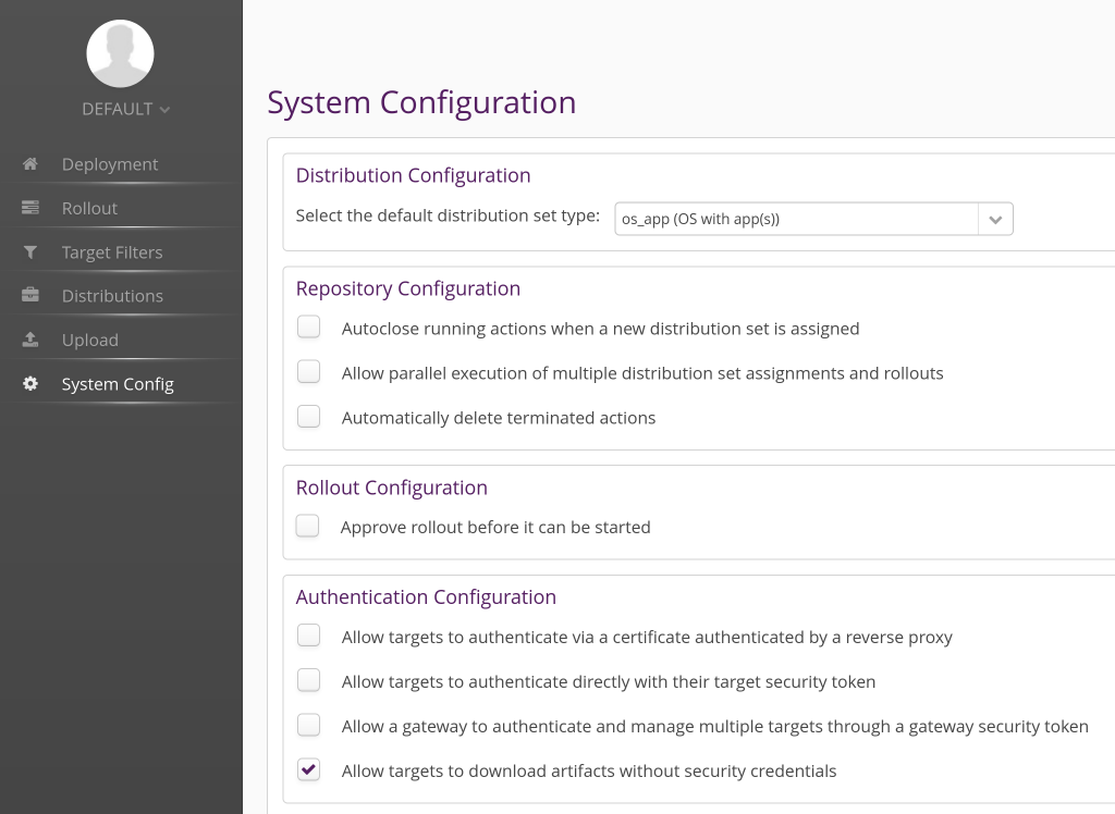
Once in the main hawkBit interface, go to the System Config tab, and enable the option Allow targets to download artifacts without security credentials. Of course, for a real deployment, you will want to set up proper credentials and authentification.

hawkBit System Config

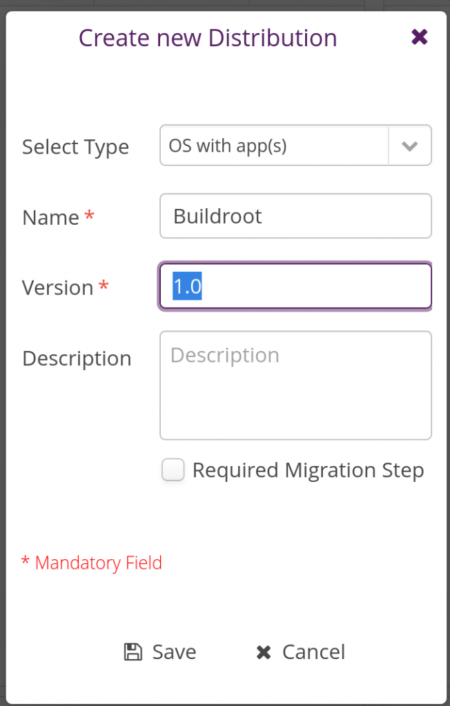
In the Distribution tab, create a new Distribution by clicking on the plus sign in the Distributions panel:

hawkBit New Distribution

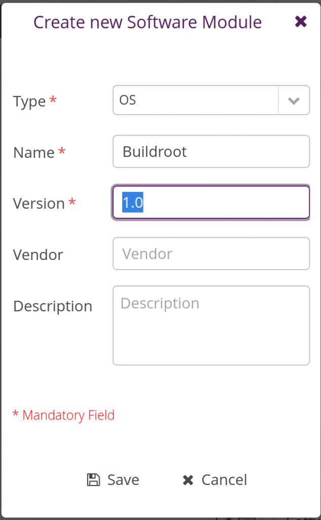
Then in the same tab, but in the Software Modules panel, create a new software module:

hawkBit New Software Module

Once done, assign the newly added software module to the Buildroot distribution by dragging-drop it into the Buildroot distribution. Things should then look like this:

hawkBit Distribution

Things are now pretty much ready on the hawkBit side now. Let’s move on with the embedded device side.

Configure swupdate

We need to adjust the configuration of swupdate to enable its Suricatta functionality which is what allows to connect to an hawkBit server.

In Buildroot’s menuconfig, enable the libcurl (BR2_PACKAGE_LIBCURL) and json-c (BR2_PACKAGE_JSON_C) packages, both of which are needed for swupdate’s Suricatta. While at it, since we will adjust the swupdate configuration and we’ll want to preserve our custom configuration, change the BR2_PACKAGE_SWUPDATE_CONFIG option to point to board/stmicroelectronics/stm32mp157-dk/swupdate.config.

Then, run:

$ make swupdate-menuconfig

to enter the swupdate configuration interface. Enable the Suricatta option, and inside this menu, in the Server submenu, verify that the Server Type is hawkBit support. You can now exit the swupdate menuconfig.

Save our custom swupdate configuration permanently:

$ make swupdate-update-defconfig

With this proper swupdate configuration in place, we now need to create a runtime configuration file for swupdate, and an init script to start swupdate at boot time. Let’s start with the runtime configuration file, which we’ll store in board/stmicroelectronics/stm32mp157-dk/overlay/etc/swupdate/swupdate.cfg, containing:

globals :
{
	postupdatecmd = "/etc/swupdate/postupdate.sh";
};

suricatta :
{
	tenant = "default";
	id = "DEV001";
	url = "http://192.168.42.1:8080";
};

We specify the path to our post-update script so that it doesn’t have to be specified on the command line, and then we specify the Suricatta configuration details: id is the unique identifier of our board, the URL is the URL to connect to the hawkBit instance (make sure to replace that with the IP address of where you’re running hawkBit). tenant should be default, unless you’re using your hawkBit instance in complex setups to for example serve multiple customers.

Our post-update script also needs to be slightly adjusted. Indeed, we will need a marker that tells us upon reboot that an update has been done, in order to confirm to the server that the update has been successfully applied. So we change board/stmicroelectronics/stm32mp157-dk/overlay/etc/swupdate/postupdate.sh to:

#!/bin/sh

PART_STATUS=$(sgdisk -A 4:get:2 /dev/mmcblk0)
if test "${PART_STATUS}" = "4:2:1" ; then
        NEXT_ROOTFS=/dev/mmcblk0p5
else
        NEXT_ROOTFS=/dev/mmcblk0p4
fi

# Add update marker
mount ${NEXT_ROOTFS} /mnt
touch /mnt/update-ok
umount /mnt

sgdisk -A 4:toggle:2 -A 5:toggle:2 /dev/mmcblk0
reboot

What we do is that we simply mount the next root filesystem, and create a file /update-ok. This file will be checked by our swupdate init script, see below.

Then, our init script will be in board/stmicroelectronics/stm32mp157-dk/overlay/etc/init.d/S98swupdate, with executable permissions, and contain:

#!/bin/sh

DAEMON="swupdate"
PIDFILE="/var/run/$DAEMON.pid"

PART_STATUS=$(sgdisk -A 4:get:2 /dev/mmcblk0)
if test "${PART_STATUS}" = "4:2:1" ; then
	ROOTFS=rootfs-2
else
	ROOTFS=rootfs-1
fi

if test -f /update-ok ; then
	SURICATTA_ARGS="-c 2"
	rm -f /update-ok
fi

start() {
	printf 'Starting %s: ' "$DAEMON"
	# shellcheck disable=SC2086 # we need the word splitting
	start-stop-daemon -b -q -m -S -p "$PIDFILE" -x "/usr/bin/$DAEMON" \
		-- -f /etc/swupdate/swupdate.cfg -L -e rootfs,${ROOTFS} -u "${SURICATTA_ARGS}"
	status=$?
	if [ "$status" -eq 0 ]; then
		echo "OK"
	else
		echo "FAIL"
	fi
	return "$status"
}

stop() {
	printf 'Stopping %s: ' "$DAEMON"
	start-stop-daemon -K -q -p "$PIDFILE"
	status=$?
	if [ "$status" -eq 0 ]; then
		rm -f "$PIDFILE"
		echo "OK"
	else
		echo "FAIL"
	fi
	return "$status"
}

restart() {
	stop
	sleep 1
	start
}

case "$1" in
        start|stop|restart)
		"$1";;
	reload)
		# Restart, since there is no true "reload" feature.
		restart;;
        *)
                echo "Usage: $0 {start|stop|restart|reload}"
                exit 1
esac

This is modeled after typical Buildroot init scripts. A few points worth mentioning:

  • At the beginning of the script, we determine which copy of the root filesystem needs to be updated by looking at which partition currently is marked “bootable”. This is used to fill in the ROOTFS variable.
  • We also determine if we are just finishing an update, by looking at the presence of a /update-ok file.
  • When starting swupdate, we pass a few options: -f with the path to the swupdate configuration file, -L to enable syslog logging, -e to indicate which copy of the root filesystem should be updated, and -u '${SURICATTA_ARGS}' to run in Suricatta mode, with SURICATTA_ARGS containing -c 2 to confirm the completion of an update.

Generate a new image with the updated swupdate, its configuration file and init script, and reboot your system.

Deploying an update

When booting, your system starts swupdate automatically:

Starting swupdate: OK
[...]
# ps aux | grep swupdate
  125 root     /usr/bin/swupdate -f /etc/swupdate/swupdate.cfg -L -e rootfs,rootfs-1 -u
  132 root     /usr/bin/swupdate -f /etc/swupdate/swupdate.cfg -L -e rootfs,rootfs-1 -u

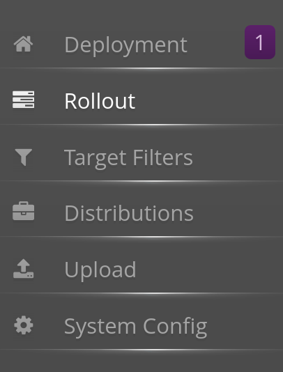
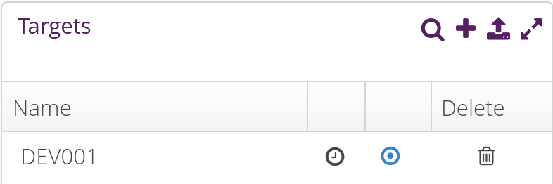
Back to the hawkBit administration interface, the Deployment tab should show one notification:

hawkBit new device notification

and when clicking on it, you should see our DEV001 device:

hawkBit new device

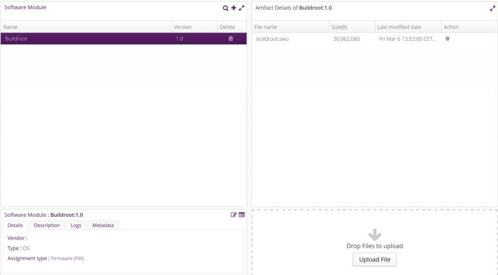
Now, go to the Upload tab, select the Buildroot software module, and click on Upload File. Upload the buildroot.swu file here:

hawkBit Upload

Back into the Deployment tab, drag and drop the Buildroot distribution into the DEV001 device. A pending update should appear in the Action history for DEV001:

hawkBit upgrade pending

The swupdate on your target will poll regularly the server (by default every 300 seconds, can be customized in the System config tab of the hawkBit interface) to know if an update is available. When that happens, the update will be downloaded and applied, the system will reboot, and at the next boot the update will be confirmed as successful, showing this status in the hawkBit interface:

hawkBit upgrade confirmed

If you’ve reached this step, your system has been successfully updated, congratulations! Of course, there are many more things to do to get a proper swupdate/hawkBit deployment: assign unique device IDs (for example based on MAC addresses or SoC serial number), implement proper authentication between the swupdate client and the server, implement image encryption if necessary, improve the upgrade validation mechanism to make sure it detects if the new image doesn’t boot properly, etc.

Conclusion

In this blog post, we have learned about firmware upgrade solutions, and specifically about swupdate. We’ve seen how to set up swupdate in the context of Buildroot, first for local updates, and then for remote updates using the hawkBit management interface. Hopefully this will be useful for your future embedded projects!

As usual, the complete Buildroot code to reproduce the same setup is available in our branch 2019.02/stm32mp157-dk-blog-7, in two commits: one for the first step implementing support just for local updates, and another one for remote update support.

Yocto Project training course available on STM32MP1 platform

Back in May 2019, we announced the availability of our Embedded Linux system development course on the STMicroelectronics STM32MP1 platform, in addition to the already supported Microchip SAMA5D3 Xplained board.

In the context of our partnership with STMicroelectronics, we are now happy to announce the availability of our Yocto Project and OpenEmbedded development training also on the STM32MP1 platform for the practical labs. We now support either the BeagleBoneBlack Wireless or the STMicroelectronics STM32MP1 platforms for this training course.

The complete training materials are available: detailed agenda, slides and practical labs. The complete source code of the training materials is also available in our Github repository.

Bootlin Yocto course on STM32MP1
Slides of Bootlin’s Yocto course for the STM32MP1

This will hopefully help customers around the world to get started with using Yocto on the STM32MP1 system-on-chip. The Yocto experts at Bootlin are available to deliver this 3-day course anywhere in the world, at your location. The first edition of this new variant of the course is going to be given this week to one of our customers in Spain. Contact us if you’re interested by having this course organized at your location!

Building a Linux system for the STM32MP1: developing a Qt5 graphical application

After showing how to build a minimal Linux system for the STM32MP157 platform, how to connect and use an I2C based pressure/temperature/humidity sensor and how to integrate Qt5 in our system, how to set up a development environment to write our own Qt5 application, we are finally going to write our Qt5 application.

List of articles in this series:

  1. Building a Linux system for the STM32MP1: basic system
  2. Building a Linux system for the STM32MP1: connecting an I2C sensor
  3. Building a Linux system for the STM32MP1: enabling Qt5 for graphical applications
  4. Building a Linux system for the STM32MP1: setting up a Qt5 application development environment
  5. Building a Linux system for the STM32MP1: developing a Qt5 graphical application
  6. Building a Linux system for the STM32MP1: implementing factory flashing
  7. Building a Linux system for the STM32MP1: remote firmware updates

Disclaimer

Before we get started in this blog post, it is important to mention that it is not meant to be a full introduction to programming applications with Qt5. This would require much more than a blog post, and the Qt web site has extensive documentation.

Also, we want to make it clear that Bootlin’s core expertise is in low-level embedded Linux development, not in Qt application development. Therefore, our example application may not show the best practices in terms of Qt development. We welcome comments and suggestions from our readers to improve the example used in this blog post.

Reading sensor data

As we’ve seen in a previous article, the sensor data is available by reading the following files:

  • /sys/bus/iio/devices/iio:device2/in_temp_input for the temperature
  • /sys/bus/iio/devices/iio:device2/in_pressure_input for the pressure
  • /sys/bus/iio/devices/iio:device2/in_humidityrelative_input for the humidity

So what we will do is writing a new class called DataProvider, which will read those files once per second, and emit a signal with the 3 values every second. Slots and signals is a fundamental mechanism in Qt, which allows to connect emitters of events to receivers for those events. In our case, the DataProvider class will emit a signal when new sensor values are read, while another class in charge of the graphical UI will receive those signals.

At this step, we don’t yet have a graphical UI, so we’ll simply add a few debugging messages in the DataProvider to make sure it works as expected.

Let’s start by adding a data-provider.h file to our project:

#ifndef DATA_PROVIDER_H
#define DATA_PROVIDER_H

#include <QtCore/QTimer>

class DataProvider: public QObject
{
    Q_OBJECT

public:
    DataProvider();

private slots:
    void handleTimer();

signals:
    void valueChanged(float temp, float pressure, float humidity);

private:
    QTimer timer;
};

#endif /* DATA_PROVIDER_H */

It creates a very simple class than inherits from QObject, with:

  • A constructor
  • A private slot handleTimer which will be used internally by the class QTimer’s instance to notify that a timer has expired. This is what will allow us to poll the sensor values every second.
  • A valueChanged signal, which will be emitted by the class every time new sensor values are available.

Then, the implementation of this class in data-provider.cpp is fairly straight-forward:

#include <QtCore/QFile>
#include <QDebug>
#include "data-provider.h"

DataProvider::DataProvider()
{
    QObject::connect(&timer, &QTimer::timeout,
		     this, &DataProvider::handleTimer);
    timer.setInterval(1000);
    timer.start();
}

void DataProvider::handleTimer()
{
    QFile temp_f("/sys/bus/iio/devices/iio:device2/in_temp_input");
    QFile pressure_f("/sys/bus/iio/devices/iio:device2/in_pressure_input");
    QFile humidity_f("/sys/bus/iio/devices/iio:device2/in_humidityrelative_input");

    if (!temp_f.open(QIODevice::ReadOnly | QIODevice::Text))
        return;
    if (!pressure_f.open(QIODevice::ReadOnly | QIODevice::Text))
        return;
    if (!humidity_f.open(QIODevice::ReadOnly | QIODevice::Text))
        return;

    float temp = QString(temp_f.readAll()).toDouble() / 1000;
    float pressure = QString(pressure_f.readAll()).toDouble() * 10;
    float humidity = QString(humidity_f.readAll()).toDouble() / 1000;

    qDebug() << "Temperature: " << temp << "Pressure: " << pressure << "Humidity: " << humidity;

    emit valueChanged(temp, pressure, humidity);
}

The constructor of the class connects the QTimer::timeout signal of the QTimer to this class handlerTimer slot, sets the timer interval to 1000 milliseconds, and starts the timer. This is what will ensure the handleTimer method gets called every second.

In the handleTimer method, we open the 3 files in sysfs, read their value and convert them to meaningful units: the temperature in Celcius, the pressure in hPA, and the humidity in percent. We then print a debugging message and emit the signal with the three values.

With this in place, we need to make sure those two files are properly taken into account by our project, by changing the .pro file as follows:

QT += widgets
SOURCES = main.cpp data-provider.cpp
HEADERS = data-provider.h
INSTALLS += target
target.path = /usr/bin

The data-provider.cpp file was added to SOURCES, while data-provider.h was added to the new HEADERS.

Now, we just need to change main.cpp to instantiate one DataProvider object:

#include <QApplication>
#include <QPushButton&ht;
#include "data-provider.h"

int main(int argc, char* argv[])
{
    QApplication app(argc, argv);
    QPushButton hello("Hello world!");
    DataProvider dp;
    hello.resize(100,30);
    hello.show();
    return app.exec();
}

With this, you can now build and run the application, and you should see every second the debugging message showing the temperature, pressure and humidity values:

# qt-sensor-demo -platform linuxfb
Temperature:  28.12  Pressure:  1003.08  Humidity:  32.235
Temperature:  28.12  Pressure:  1003.07  Humidity:  32.246
Temperature:  28.12  Pressure:  1003.06  Humidity:  32.256
Temperature:  28.12  Pressure:  1003.08  Humidity:  32.267

Displaying sensor data

We now want to display the sensor data. For this, we'll create a UI with two panels, one to display the numeric value of the temperature, humidity and pressure, and another panel with a chart of the temperature. At the bottom of the screen, two buttons Values and Chart will allow to switch between both panels.

So, we'll create a Window class to encapsulate the overall window layout and behavior, and a Values class providing the widget showing the 3 values. We'll leave the chart implementation to the next section. To help you follow the code in this section, here is a diagram that shows the different widgets and how they will be grouped together in our user interface:

Qt Sensor demo UI

Let's start by implementing the Values widget, which will be used to show the 3 numeric values, one below each other. The values.h file will look like this:

#ifndef VALUES_H
#define VALUES_H

#include <QWidget>

class QLabel;

class Values : public QWidget
{
    Q_OBJECT

public:
    Values();

public slots:
    void handleValueChanged(float temp, float pressure, float humidity);

private:
    QLabel *temperature_v;
    QLabel *pressure_v;
    QLabel *humidity_v;
};

#endif /* VALUES_H */

So it has a simple constructor, a slot to be notified of new values available, and 3 text labels to display the 3 values. The implementation in values.cpp is:

// SPDX-License-Identifier: MIT
#include <QtWidgets>
#include "values.h"

Values::Values()
{
    QVBoxLayout *layout = new QVBoxLayout;

    QLabel *temperature_l = new QLabel(tr("Temperature (°C)"));
    QLabel *pressure_l = new QLabel(tr("Pressure (hPa)"));
    QLabel *humidity_l = new QLabel(tr("Humidity (%)"));

    temperature_v = new QLabel();
    pressure_v = new QLabel();
    humidity_v = new QLabel();

    QFont f = temperature_v->font();
    f.setPointSize(28);
    f.setBold(true);
    temperature_v->setFont(f);
    pressure_v->setFont(f);
    humidity_v->setFont(f);
    temperature_v->setAlignment(Qt::AlignRight | Qt::AlignVCenter);
    pressure_v->setAlignment(Qt::AlignRight | Qt::AlignVCenter);
    humidity_v->setAlignment(Qt::AlignRight | Qt::AlignVCenter);

    layout->addWidget(temperature_l);
    layout->addWidget(temperature_v);
    layout->addWidget(pressure_l);
    layout->addWidget(pressure_v);
    layout->addWidget(humidity_l);
    layout->addWidget(humidity_v);

    setLayout(layout);
}

void Values::handleValueChanged(float temp, float pressure, float humidity)
{
    temperature_v->setText(QString::number(temp, 'f', 2));
    pressure_v->setText(QString::number(pressure, 'f', 1));
    humidity_v->setText(QString::number(humidity, 'f', 1));
}

The constructor creates 3 text labels for the legends ("Temperature (°C)", "Pressure (hPA)" and "Humidity (%)"), then instantiates the 3 text labels for the values themselves. It sets up the font and text alignment properties for those labels, and then adds all widgets in a QVBoxLayout so that they all appear vertically below each other.

The handleValueChanged slot simply updates the text labels contents with the new sensor values, doing the proper text formatting on the way.

With the Values class implemented, we can now implement the main Window class. The window.h will contain:

#ifndef WINDOW_H
#define WINDOW_H

#include <QWidget>

class Values;

class Window : public QWidget
{
    Q_OBJECT

public slots:
    void handleValueChanged(float temp, float pressure, float humidity);

public:
    Window();

private:
    Values *values;
};

#endif

Beyond a simple constructor, it has a slot to receive new sensor values, and a reference to a Values widget instance.

The implementation in window.cpp is as follows:

#include <QtWidgets>

#include "window.h"
#include "values.h"

Window::Window()
{
    values = new Values;
    QVBoxLayout *layout = new QVBoxLayout;
    QHBoxLayout *buttons = new QHBoxLayout;

    QPushButton *values_button = new QPushButton("Values");
    QPushButton *chart_button = new QPushButton("Chart");

    buttons->addWidget(values_button);
    buttons->addWidget(chart_button);

    layout->addWidget(values);
    layout->addLayout(buttons);

    setLayout(layout);

    setWindowTitle(tr("Sensors"));
}

void Window::handleValueChanged(float temp, float pressure, float humidity)
{
    values->handleValueChanged(temp, pressure, humidity);
}

The constructor creates a horizontal layout QHBoxLayout with two buttons: Values and Chart. Those will be used in the next section to switch between the Values panel and the Chart panel. For now, they don't do anything.

Then, the constructor adds the Value widget, and the horizontal layout box with the buttons into a vertical box layout, assigns the main window layout and defines the window title.

The handleValueChanged slot implementation just forwards the call to the Values::handleValueChanged method.

Now, obviously main.cpp needs to be changed: instead of creating a button, we'll create our window, and do a bit of additional setup:

#include <QApplication>
#include "window.h"
#include "data-provider.h"

int main(int argc, char* argv[])
{
    QApplication app(argc, argv);
    DataProvider dp;
    Window window;

    QObject::connect(&dp, &DataProvider::valueChanged,
		     &window, &Window::handleValueChanged);

    window.setFixedSize(480, 800);
    window.setStyleSheet("background-color: white;");
    window.show();
    return app.exec();
}

So, not only we create the Window, but more importantly, we connect the valueChanged signal of DataProvider to the handleValueChanged slot of Window. We define the window size (which is fixed, to match the STM32MP15 Discovery board panel) and set the background color of the application.

Obviously, the qt-sensor-demo.pro file needs to be adjusted to build our new files. It now looks like this:

QT += widgets
SOURCES = main.cpp data-provider.cpp window.cpp values.cpp
HEADERS = data-provider.h window.h values.h
INSTALLS += target
target.path = /usr/bin

With this done, we can run the Qt5 application on our target, and see:

Qt5 application showing the I2C sensor data

Graphing the temperature

The final part of developing our application is to implement a graph showing the evolution of temperature over time. For this, we are going to use the very convenient Qt Charts module, which is available in a separate Qt module from the base of Qt.

To implement the graph widget itself, we'll create a new Chart class:

#ifndef CHART_H
#define CHART_H

#include <QtCharts/QChart>

QT_CHARTS_BEGIN_NAMESPACE
class QSplineSeries;
class QValueAxis;
QT_CHARTS_END_NAMESPACE

QT_CHARTS_USE_NAMESPACE

class Chart: public QChart
{
    Q_OBJECT

public:
    Chart(QGraphicsItem *parent = 0, Qt::WindowFlags wFlags = 0);

public slots:
    void handleValueChanged(float temp, float pressure, float humidity);

private:
    QSplineSeries *m_series;
    QStringList m_titles;
    QValueAxis *m_axisX;
    QValueAxis *m_axisY;
    int xpos;
};

#endif /* CHART_H */

This class inherits from the QChart class provided by Qt. It provides a constructor and destructor, a slot that allows to receive notification of new sensor values, and it has a number of private variables to manage the chart itself.

Let's go through the implementation of this class now:

#include "chart.h"
#include <QtCharts/QAbstractAxis>
#include <QtCharts/QSplineSeries>
#include <QtCharts/QValueAxis>

Chart::Chart(QGraphicsItem *parent, Qt::WindowFlags wFlags):
    QChart(QChart::ChartTypeCartesian, parent, wFlags),
    m_series(0),
    m_axisX(new QValueAxis()),
    m_axisY(new QValueAxis()),
    xpos(0)
{
    m_series = new QSplineSeries(this);
    QPen pen(Qt::red);
    pen.setWidth(2);
    m_series->setPen(pen);
    m_series->append(xpos, 30);

    addSeries(m_series);

    addAxis(m_axisX,Qt::AlignBottom);
    addAxis(m_axisY,Qt::AlignLeft);
    m_series->attachAxis(m_axisX);
    m_series->attachAxis(m_axisY);
    m_axisX->setTickCount(5);
    m_axisX->setRange(0, 60);
    m_axisY->setRange(0, 50);

    QFont f = m_axisX->labelsFont();
    f.setPointSize(8);
    m_axisX->setLabelsFont(f);
    m_axisY->setLabelsFont(f);

    setMargins(QMargins(0,0,0,0));

    setTitle("Temperature (°C)");
    legend()->hide();
}

void Chart::handleValueChanged(float temp, float pressure, float humidity)
{
    Q_UNUSED(pressure);
    Q_UNUSED(humidity);
    m_series->append(xpos, temp);
    xpos++;
    if (xpos >= 60)
      scroll(plotArea().width() / 60, 0);
}

The constructor simply sets up the QChart we inherit from: defining the axis, their range, the pen width and color, etc. On the X axis (time), we are going to show 60 measurements, and since our handleValueChanged slot is going to be called every second, it means our graph will show the last 60 seconds of temperature measurement. On the Y axis (temperature), we can show temperatures from 0°C to 50°C. Of course, this is all very hardcoded in this example, for simplicity.

The handleValueChanged slot appends the new temperature value to the graph, and then updates the area displayed by the graph so that always the last 60 seconds are visible.

Now, we need to integrate this to our existing Window class, so that we can display the chart, and switch between the numeric values and the chart. First, we need to do some changes in window.h, and below we'll show only the diff to make the differences very clear:

diff --git a/window.h b/window.h
index 3d63d38..05d1f39 100644
--- a/window.h
+++ b/window.h
@@ -3,8 +3,12 @@
 #define WINDOW_H
 
 #include <QWidget>
+#include <QtCharts/QChartView>
+
+QT_CHARTS_USE_NAMESPACE
 
 class Values;
+class Chart;
 
 class Window : public QWidget
 {
@@ -13,11 +17,17 @@ class Window : public QWidget
 public slots:
     void handleValueChanged(float temp, float pressure, float humidity);
 
+private slots:
+    void chartButtonClicked();
+    void valuesButtonClicked();
+
 public:
     Window();
 
 private:
     Values *values;
+    QChartView *chartView;
+    Chart *chart;
 };
 
 #endif

So, we're defining two private slots that will be used for the two buttons that allow to switch between the numeric values and the chart, and then we add two variables, one for the chart itself, and one for the QChartView (which basically renders the graph into a widget).

Then, in window.cpp, we do the following changes:

diff --git a/window.cpp b/window.cpp
index aba2862..d654964 100644
--- a/window.cpp
+++ b/window.cpp
@@ -3,28 +3,54 @@
 
 #include "window.h"
 #include "values.h"
+#include "chart.h"
 
 Window::Window()
 {
     values = new Values;
+    chart = new Chart;
     QVBoxLayout *layout = new QVBoxLayout;
     QHBoxLayout *buttons = new QHBoxLayout;
 
     QPushButton *values_button = new QPushButton("Values");
     QPushButton *chart_button = new QPushButton("Chart");
 
+    QObject::connect(chart_button, &QPushButton::clicked,
+                    this, &Window::chartButtonClicked);
+    QObject::connect(values_button, &QPushButton::clicked,
+                    this, &Window::valuesButtonClicked);
+
     buttons->addWidget(values_button);
     buttons->addWidget(chart_button);
 
+    chartView = new QChartView(chart);
+    chartView->setRenderHint(QPainter::Antialiasing);
+
     layout->addWidget(values);
+    layout->addWidget(chartView);
     layout->addLayout(buttons);
 
     setLayout(layout);
 
+    chartView->hide();
+
     setWindowTitle(tr("Sensors"));
 }
 
 void Window::handleValueChanged(float temp, float pressure, float humidity)
 {
     values->handleValueChanged(temp, pressure, humidity);
+    chart->handleValueChanged(temp, pressure, humidity);
+}
+
+void Window::chartButtonClicked()
+{
+    values->hide();
+    chartView->show();
+}
+
+void Window::valuesButtonClicked()
+{
+    values->show();
+    chartView->hide();
 }

So, in the constructor we are connecting the clicked signals of the two buttons to their respective slots. We create the Chart object, and then the QChartView to render the graph. We add the latter as an additional widget in the QVBoxLayout, and we hide it.

The existing handleValueChanged slot is modified to also update the Chart object with the new sensor values.

Finally, the new chartButtonClicked and valuesButtonClicked slots implement the logic that is executed when the buttons are pressed. We simply hide or show the appropriate widget to display either the numeric values or the chart. There is probably a nicer way to achieve this in Qt, but this was good enough for our example.

Now that the source code is in place, we of course need to adjust the build logic in qt-sensor-demo.pro:

--- a/qt-sensor-demo.pro
+++ b/qt-sensor-demo.pro
@@ -1,6 +1,6 @@
 # SPDX-License-Identifier: MIT
-QT += widgets
-SOURCES = main.cpp data-provider.cpp window.cpp values.cpp
-HEADERS = data-provider.h window.h values.h
+QT += widgets charts
+SOURCES = main.cpp data-provider.cpp window.cpp values.cpp chart.cpp
+HEADERS = data-provider.h window.h values.h chart.h
 INSTALLS += target
 target.path = /usr/bin

Besides the obvious addition of the chart.cpp and chart.h file, the other important addition is charts to the QT variable. This tells qmake that our application is using the Qt Charts, and that we therefore need to link against the appropriate libraries.

Building the application

At this point, if you try to build the application, it will fail because QtCharts has not been built as part of our Buildroot configuration. In order to address this, run Buildroot's make menuconfig, enable the BR2_PACKAGE_QT5CHARTS option (in Target packages -> Graphic libraries and applications -> Qt5 -> qt5charts).

Then, run the Buildroot build with make, and reflash the resulting SD card image.

Now, you can build again your application, either with Qt Creator if you've been using Qt Creator, or manually. If you build it manually, you'll have to run qmake again to regenerate the Makefile, and then build with make.

When you run the application on the target, the GUI will display the same numeric values as before, but now if you press the Chart button, it will show something like:

Qt5 application with chart

Adjusting the Buildroot package

We have for now been building this application manually, but as explained in our previous blog post, we really want Buildroot to be able to build our complete system, including our application. For this reason, we had created a qt-sensor-demo package, which gets our application source code, configures it with qmake, builds it and installs it.

However, with the new use of Qt Charts, our qt-sensor-demo package needs a few adjustements:

  • The Config.in file needs an additional select BR2_PACKAGE_QT5CHARTS, to make sure Qt Charts are enabled in the Buildroot configuration
  • The qt-sensor-demo.mk file needs an additional qt5charts in the QT_SENSOR_DEMO_DEPENDENCIES variable to make sure the qt5charts package gets built before qt-sensor-demo

With this in place, you can run:

make qt-sensor-demo-rebuild
make

And you have an SD card image that includes our application!

Starting the application automatically at boot time

The next and almost final step for this blog post is to get our application automatically started at boot time. We can simply add a small shell script on the target in /etc/init.d/: the default Buildroot configuration for the init system will execute all scripts named Ssomething in /etc/init.d/. We'll add a file named package/qt-sensor-demo/S99qt-sensor-demo with these contents:

#!/bin/sh

DAEMON="qt-sensor-demo"
DAEMON_ARGS="-platform linuxfb"
PIDFILE="/var/run/qt-sensor-demo.pid"

start() {
	printf 'Starting %s: ' "$DAEMON"
	start-stop-daemon -b -m -S -q -p "$PIDFILE" -x "/usr/bin/$DAEMON" -- $DAEMON_ARGS
	status=$?
	if [ "$status" -eq 0 ]; then
		echo "OK"
	else
		echo "FAIL"
	fi
	return "$status"
}

stop () {
	printf 'Stopping %s: ' "$DAEMON"
	start-stop-daemon -K -q -p "$PIDFILE"
	status=$?
	if [ "$status" -eq 0 ]; then
		rm -f "$PIDFILE"
		echo "OK"
	else
		echo "FAIL"
	fi
	return "$status"
}

restart () {
	stop
	sleep 1
	start
}

case "$1" in
        start|stop|restart)
		"$1";;
	reload)
		# Restart, since there is no true "reload" feature.
		restart;;
        *)
                echo "Usage: $0 {start|stop|restart|reload}"
                exit 1
esac

This is the canonical init script used in Buildroot to start system daemons and services, and is modeled after the one in package/busybox/S01syslogd. It uses the start-stop-daemon program to start our application in the background.

Then, to get this init script installed, we need to adjust package/qt-sensor-demo/qt-sensor-demo.mk with the following additional lines:

define QT_SENSOR_DEMO_INSTALL_INIT_SYSV
        $(INSTALL) -D -m 755 package/qt-sensor-demo/S99qt-sensor-demo \
                $(TARGET_DIR)/etc/init.d/S99qt-sensor-demo
endef

This ensures that the init script gets installed in /etc/init.d/S99qt-sensor-demo as part of the build process of our qt-sensor-demo package. Note that an init script works fine if you're using the Busybox init implementation or the sysvinit init implementation (we're using the default Buildroot setup here, which uses the Busybox init implementation). If you want to use systemd as an init implementation, then a different setup is necessary.

With this done, you simply need to reinstall the application and regenerate the SD card image

$ make qt-sensor-demo-reinstall
$ make

You can now test your SD card image on you board, and you should see the application being started automatically, with the following messages at boot time

Starting dropbear sshd: OK
Starting qt-sensor-demo: OK

Welcome to Buildroot

Avoid unnecessary logging on the display panel

In our current setup, the kernel messages are being sent to both the serial port and the framebuffer console, which means they appear on the display panel. This is not very pretty, and we would like the display to remain black until the application starts, while keeping the kernel messages on the serial port for debugging purposes. Also, we would like the framebuffer console text cursor to not be displayed, to really have a fully black screen. To achieve this we will add two arguments on the Linux kernel command line:

  • console=ttySTM0,115200, which will tell the Linux kernel to only use the serial port as the console, and not all registered consoles, which would include the framebuffer console. This option will make sure the kernel messages are not displayed on the screen.
  • vt.global_cursor_default=0, which will tell the Linux kernel to not display any cursor on the framebuffer console.

So, to add those options, we simply modify board/stmicroelectronics/stm32mp157-dk/overlay/boot/extlinux/extlinux.conf in Buildroot as follows:

label stm32mp15-buildroot
  kernel /boot/zImage
  devicetree /boot/stm32mp157c-dk2.dtb
  append root=/dev/mmcblk0p4 rootwait console=ttySTM0,115200 vt.global_cursor_default=0

Of course, rebuild the SD card image with make, reflash and test the result on your STM32MP1 platform.

Conclusion

In this blog post, we have seen how to write a real (but admittedly very simple) Qt application, how to make it read and display sensor data, and how to integrate this application so that it gets started at boot time.

You can find the Buildroot changes corresponding to this blog post in the 2019.02/stm32mp157-dk-blog-5 branch of our repository. The qt-sensor-demo application code can be found in the blog-5 branch of this application Git repository.

Stay tuned for our next blog post about factory flashing and OTA update!

STM32MP1 system-on-chip, Bootlin member of ST Partners program

Earlier this year at Embedded World, STMicroelectronics announced the release of their first MPU, the STM32MP1 system-on-chip. Bootlin has been selected as one of the companies offering engineering and training services to be part of the ST Partners program around this new platform. In this blog post, we will give more details about STM32MP1 and Bootlin’s initial efforts on this platform.

The STM32MP1 platform

For the past several years, STMicroelectronics has developed a range of 32-bit microcontrollers based on the ARM Cortex-M cores. The most high-end ones, based on Cortex-M4 and M7, were powerful enough to run a Linux operating system with external RAM attached, and ST has been very active in adding support for these micro-controllers in the upstream U-Boot and Linux projects. However, the Cortex-M4 and M7 being MMU-less processor cores, Linux could work only with a number of limitations, preventing from using some complex Linux software stacks.

Block diagram of the STM32MP157
With the STM32MP1, ST is now offering a full-featured microprocessor, based on the combination of one or two Cortex-A7 cores (650 Mhz), one Cortex-M4 core (209 Mhz) and a wide variety of peripherals. The STM32MP1 is currently available in 3 variants:

  • STM32MP151, featuring one Cortex-A7, one Cortex-M4, and the common set of peripherals
  • STM32MP153, featuring two Cortex-A7, one Cortex-M4, the common set of peripherals plus CAN-FD
  • STM32MP157, featuring two Cortex-A7, one Cortex-M4, the common set of peripherals plus a 3D GPU, a DSI display interface and CAN-FD

The hardware blocks integrated in the STM32MP1 offers a large amount of features and connectivity options:

  • External DDR controller, supporting up to LPDDR2/3 and DDR3
  • QuadSPI memory interface
  • NAND flash controller, with built-in ECC capability
  • 6 I2C controllers
  • 4 UARTs and 4 USARTs
  • 6 SPI controllers
  • 4 SAI audio interfaces
  • HDMI-CEC interface
  • 3 SD/MMC controllers
  • 2 CAN controllers
  • 2 USB host + 1 USB OTG controllers
  • 1 Gigabit Ethernet MAC
  • Camera interface (parallel)
  • 2 ADCs, 2 DACs, 1 digital filter for sigma delta modulators
  • LCD controller supporting up to 1366×768
  • GPU from Vivante (which means open-source support is available!)
  • MIPI DSI
  • Plenty of timers
  • Crypto accelerators, random number generator (only in the C variants of the SoC)
  • Secure boot (only in the C variants of the SoC)

This combination of a wide range of connectivity options, graphics support with GPU support, and a Cortex-M4 for real-time logic, makes the STM32MP1 interesting for a large number of applications.

Software support for the STM32MP1

Bootlin being a consulting company specialized in low-level Linux software for embedded platforms, it is obviously a key aspect we looked at for the STM32MP1 platform.

First of all, a number of hardware blocks used in the STM32MP1 platform were already used on previous micro-controllers from ST and were therefore already supported in upstream projects such as U-Boot and Linux. The fact that these micro-controller products can run upstream versions of U-Boot and Linux is a good indication of ST’s strategy in terms of upstream support.

Then, even before the STM32MP1 product was publicly announced, a significant number of ST engineers had already started contributing to upstream TF-A, U-Boot and Linux the support for various pieces needed for the STM32MP1. Even if the support is not entirely upstream at this point, this strategy of starting the upstreaming effort ahead of the product announcement is very good.

Even though the work towards open-source GPU support has tremendously progressed over the past years, GPUs were notoriously known for being difficult to support in a fully open-source software stack. It is interesting to see that ST has chosen the GPU from Vivante for this STM32MP1, as Vivante is one of the first embedded GPU supported by Mesa, the open-source OpenGL implementation. Vivante GPUs are already used in a number of other SoCs, especially from NXP, and the Vivante open-source support, called etnaviv has therefore already seen some significant usage in production.

Until all the support for the STM32MP1 is fully upstreamed, ST provides publicly available Git repositories for all pieces of the software stack:

In addition to the availability of the code, there is also plenty of documentation available in the Development zone of the STM32 MPU wiki.

Hardware platforms for the STM32MP1

ST provides a low-cost evaluation platform called Discovery, available in two versions:

  • STM32MP157A-DK1, which features the STM32MP157A processor (all features, but without secure boot), LEDs, push buttons, Ethernet, one USB-C connector, 4 USB-A connectors, HDMI, microSD, analog audio, Arduino and RPi compatible connectors. The cost is $69.
  • STM32MP157C-DK2 features the STM32MP157C processor (all features including secure boot), and has the same features as the DK1 variant, with the addition of a DSI panel with touch and a WiFi/Bluetooth chip. The cost is $99.
STM32MP157-DK2 board

ST also provides some more feature-complete evaluation boards: the STM32MP157A-EV1 and STM32MP157C-EV1, which only differ by the lack or availability of secure boot support. They offer more hardware features than the Discovery platforms, and are obviously available at a higher cost, $399.

In addition to these platforms provided by ST, several manufacturers have already announced a number of boards or system-on-module based on the STM32MP1:

OSD32MP15x system-in-package

Bootlin member of ST’s partner program

Bootlin is proud to have been chosen by ST to be part of its partner program when the STM32MP1 platform was announced. As a software partner, Bootlin can offer its training and engineering services to customers using the STM32MP1. We can provide:

  • Engineering for the development of Linux Board Support Packages for STM32MP1 platforms: porting U-Boot, porting Linux, writing Linux device drivers, delivering a fully integrated and optimized Linux system generated with Yocto or Buildroot
  • Training on embedded Linux, Linux kernel development and Yocto usage around the STM32MP1 platform

Bootlin trainings on STM32MP1

As a ST partner, Bootlin will be porting two of its existing training courses to the STM32MP1 platform: this means that all the practical labs in those courses will take place on the STM23MP157 Discovery board. We will soon be announcing:

Of course, as Bootlin has always done, all the training materials will be made freely available, under the same Creative Commons license we already use for existing training materials.

Building a Linux system for STM32MP1

The STM32MP1 being the first micro-processor in this family of SoCs from ST, a number of companies will most likely migrate from a micro-controller environment to a micro-processor one. This means moving from a situation where only a bare-metal application or a simple RTOS is used, to a situation where a feature-rich operating system such as Linux is being used. This migration is not always trivial as it requires gaining a lot of knowledge about U-Boot, the Linux kernel, Linux system integration and development, and more.

In order to help with this, in addition to the training courses described above, we will soon start publishing a series of blog posts that describe step by step how to build a Linux system for the STM32MP157 Discovery Kit, all the way up to reading data from an I2C sensor, and displaying them in a Qt5 based application. Stay tuned on our blog for those articles in the next few weeks!