Boot time: choose your kernel loading address carefully

When the compressed and uncompressed kernel images overlap

At least on ARM32, there seems to be many working addresses where the compressed kernel can be loaded in RAM. For example, one can load the compressed kernel at offset 0x1000000 (16 MB) from the start of RAM, and the Device Tree Blog (DTB) at offset 0x2000000 (32 MB). Whatever this loading address, the kernel is then decompressed at offset 0x8000 from the start of RAM, as explained this the famous How the ARM32 Linux kernel decompresses article from Linus Walleij.

There is a potential issue with the loading address of the compressed kernel, as explained in the article too. If the compressed kernel is loaded too close to the beginning of RAM, where the kernel must be decompressed, there will be an overlap between the two. The decompressed kernel will overwrite the compressed one, potentially breaking the decompression process.

Overlapping compressed and decompressed kernel

As you see in the above diagram, when this happens, the bootstrap code in the compressed kernel will first copy the compressed image to a location that’s far enough to guarantee that the decompressed kernel won’t overlap it. However, this extra step in the boot process has a cost.

Measuring boot time impact

In the context of updating our materials for our upcoming Embedded Linux Boot Time Optimization course in June, we measured this additional time on the STM32MP157A-DK1 Discovery Kit from STMicroelectronics, with a dual-core ARM Cortex-A7 CPU running at 650 MHz.

Initially, in our Embedded Linux System Development course, we were booting the DK1 board as follows:

ext4load mmc 0:4 0xc0000000 zImage; ext4load mmc 0:4 0xc4000000 dtb; bootz 0xc0000000 - 0xc4000000

0xc0000000 is exactly the beginning of RAM! We are therefore in the overlap situation.

We used grabserial from Tim Bird to measure the time between Starting kernel in U-Boot and when the compressed kernel starts executing (Booting Linux on physical CPU 0x0):

...
[4.451996 0.000124] Starting kernel ...
[0.001838 0.001838] 
[2.439980 2.438142] [    0.000000] Booting Linux on physical CPU 0x0
...

On a series of 5 identical tests, we obtained an average time of 2,440 ms, with a standard deviation of 0.4 ms.

Then, we measured the optimum case, in which the compressed kernel is loaded far enough from the beginning of RAM so that no overlap is possible:

No overlap between compressed and decompressed kernel

Here we chose to load the kernel at 0xc2000000:

ext4load mmc 0:4 0xc2000000 zImage; ext4load mmc 0:4 0xc4000000 dtb; bootz 0xc2000000 - 0xc4000000

On a series of 5 identical tests, we obtained an average time of 2,333 ms, with a standard deviation of 0.7 ms.

The new average is 107 ms smaller, which you are likely to consider as a worthy reduction, if you have experience with boot time reduction projects.

What to remember

In your embedded projects, if you are using a compressed kernel, make sure it is loaded far enough from the beginning of RAM, leaving enough space for the decompressed kernel to fit in between. Otherwise, your system will still be able to boot, but depending on the speed of your CPU and storage, it will be slower, from a few tens to a few hundreds of milliseconds.

We checked the How to optimize the boot time page on the STM32 wiki, and it recommends optimum loading addresses: 0xc2000000 for the kernel and 0xc4000000 for the device tree. This way, the upper limit for the decompressed kernel is 32 MB, which is more than enough.

If you are directly using an uncompressed kernel, which is more rare, you should also make sure that it is loaded at an optimum location, so that there is no need to move it before starting it.

Building a Linux system for the STM32MP1: implementing factory flashing

After several months, it’s time to resume our series of blog posts about building a Linux system for the STM32MP1 platform. After showing how to build a minimal Linux system for the STM32MP157 platform, how to connect and use an I2C based pressure/temperature/humidity sensor and how to integrate Qt5 in our system, how to set up a development environment to write our own Qt5 application and how to develop a Qt5 application, we will now cover the topic of factory flashing.

List of articles in this series:

  1. Building a Linux system for the STM32MP1: basic system
  2. Building a Linux system for the STM32MP1: connecting an I2C sensor
  3. Building a Linux system for the STM32MP1: enabling Qt5 for graphical applications
  4. Building a Linux system for the STM32MP1: setting up a Qt5 application development environment
  5. Building a Linux system for the STM32MP1: developing a Qt5 graphical application
  6. Building a Linux system for the STM32MP1: implementing factory flashing
  7. Building a Linux system for the STM32MP1: remote firmware updates

What is factory flashing ?

So far, we have used a microSD card as storage for the Linux system running on the STM32MP1 platform. Since this media is removable, we can easily switch the microSD card back and forth between the STM32MP1 platform and our development workstation, which is nice during development and debugging.

However, an actual product will most likely use some form of non-removable persistent storage, typically an eMMC or a NAND flash. While not available on the STM32MP1-DK1 board probably for cost reasons, these storage devices are very common in most embedded systems. For example, the STM32MP157A-EV1 board provides three non-removable persistent storage devices: a 4 GB eMMC, a 1 GB NAND flash, and a 64 MB QSPI NOR flash.

When such storage devices are shipped by their manufacturer, they are typically empty. Therefore, as part of the manufacturing process of your embedded systems, you will have to load the relevant storage device with your Linux system, applications and data, so that the embedded system is fully operational: this is the process referred to as factory flashing in this blog post.

If you are doing a very high volume product, you can ask your eMMC or NAND flash vendor to pre-load a system image on the storage before it is shipped to you and assembled on your board. However, many companies do products with volumes that are not large enough to make such a strategy possible: in this case, you really receive an empty storage device, and have to flash it.

A first possibility to flash the non-removable storage is to use a removable storage device, boot a Linux system on the device, and use it to flash the non-removable storage. This can definitely be a possible option in some situations, but it is not always possible (if there’s no removable storage device interface at all) or not always practical.

However, most system-on-chips, including the STM32MP1 include some ROM code that the processor executes at boot time, even before it loads the first stage bootloader. This ROM code is primarly responsible for loading the first stage bootloader into memory, but it also very often offers a communication channel with the outside world, which can be used to gain control of a platform that has nothing at all on its storage. This communication channel is typically over USB or UART, and most often uses a custom, vendor-specific protocol, which is understood by vendor-specific tools. This protocol generally allows to send some code to the target and get it executed, which is sufficient to be able to reflash the target device.

Here are a few examples with system-on-chips from various vendors:

  • The ROM code of the NXP i.MX processors implements a USB-based protocol, which can be interfaced either using the NXP-provided mfgtools, or using the community-developed imx_usb_loader. The latter was presented in one of our earlier blog posts about i.MX6 factory flashing.
  • The ROM code of Microchip SAMA5 processors implements a USB-based protocol, which can be interfaced using a tool called SAM-BA
  • The ROM code of Rockchip processors implements a USB-based protocol, which can be interfaced either using a Rockchip-specific tool called rkdeveloptool
  • The ROM code of the ST STM32MP15 processors also implement a USB-based protocol, which can be interfaced using the STM32 Cube Programmer

Obviously, in this blog post, we are going to use the latter, STM32 Cube Programmer, to flash our STM32MP1 platform. Since the DK2 board only has a removable device, we will use the tool to flash the SD card, but the process and logic would be the same for any other (non-removable) storage device.

Getting and installing STM32 Cube Programmer

While ST generally has very good upstream and open-source support for its products, the STM32 Cube Programmer unfortunately doesn’t follow this strategy: you need to be registered on the ST web site to download it, and its source code is not available. Due to this registration process, we for example cannot create a Buildroot package that would automatically download and install this tool for you.

So, follow the process to create an account on the ST web site, and then go to the STM32 Cube Programmer page. At the time of this writing, the latest version is 2.2.1, but according this Wiki page, this version doesn’t work for the STM32MP1 platform. Instead, select to download the 2.2.0 version, which is known to work. You will then download a file called en.stm32cubeprog.zip (it doesn’t have the version in its name, which isn’t great) weighting 187 MB, and which has the SHA256 hash 91107b4d605d126f5c32977247d7419d42abb2655848d2d1a16d52f5f7633d2d.

Extract this ZIP file somewhere in your system, and then run the SetupSTM32CubeProgrammer-2.2.0.linux executable:

$ ./SetupSTM32CubeProgrammer-2.2.0.linux

Got through the installation steps. On our system, we customized the installation path to be just $HOME/stm32cube, and the remainder of this blog post will assume this is where you installed the STM32 Cube Programmer.

In this blog post, we are only going to use the command line interface (CLI) of STM32 Cube Programmer, so just make sure you can run the corresponding tool:

$ ~/stm32cube/bin/STM32_Programmer_CLI
      -------------------------------------------------------------------
                        STM32CubeProgrammer v2.2.0
      -------------------------------------------------------------------


Usage :
STM32_Programmer_CLI.exe [command_1] [Arguments_1][[command_2] [Arguments_2]...]
[...]

Testing the communication with the board

On the back of the board, there is a two-way DIP switch labeled SW1, which is used to configure the boot mode. When both are “ON”, the board boots from the SD card. When both are “OFF”, the board enters the “USB boot for flashing mode”, which is what we are going to use. So switch both switches to OFF, and reset the board.

Plug an additional USB-C cable from the board CN7 connector (which is located between the HDMI port and the 4 USB host ports).

USB-C connection for factory flashing

Then, reset the board. If you run lsusb on your Linux workstation, you should see a new device:

Bus 003 Device 011: ID 0483:df11 STMicroelectronics STM Device in DFU Mode

Then, you can ask STM32_Programmer_CLI to list the devices it sees over USB. This needs root permissions (unless appropriate udev rules are created):

$ sudo ~/stm32cube/bin/STM32_Programmer_CLI -l usb
      -------------------------------------------------------------------
                        STM32CubeProgrammer v2.2.0
      -------------------------------------------------------------------

=====  DFU Interface   =====

Total number of available STM32 device in DFU mode: 1

  Device Index           : USB1
  USB Bus Number         : 003
  USB Address Number     : 003
  Product ID             : DFU in HS Mode @Device ID /0x500, @Revision ID /0x0000
  Serial number          : 004200343338510534383330
  Firmware version       : 0x0110
  Device ID              : 0x0500

Good, the STM32CubeProgrammer tool is seeing our board, and we see that the Device Index is USB1. Keep that in mind for the next steps.

Change the Linux system boot chain

STM32CubeProgrammer works by sending a U-Boot bootloader over USB, and then talking to this U-Boot to make it erase the MMC or NAND flash, and make it write some data to those storage devices. However, for some reason, STM32CubeProgrammer doesn’t work with the boot flow we have used so far, which uses the U-Boot SPL as the first-stage bootloader, and U-Boot itself as the second stage bootloader. It only works when the first stage bootloader is the Arm Trusted Firmware, also called TF-A. You can get more details about the different possible boot chains on STM32MP1 on this Wiki page.

Due to this constraint, we are going to switch our Buildroot configuration to use TF-A instead of U-Boot SPL as the first stage bootloader.

First of all, we need to backport two Buildroot commits, which did not exist in the Buildroot 2019.02 we are using, but have been integrated later. The first commit, 9dbc934217e170578d4cbfdf524bc1b3988d0b9e allows to build TF-A for ARM 32-bit platforms, while the second commit, e4d276c357fdf9f19f99f826cab63f373687f902 allows to provide a custom name for the TF-A image name.

In Buildroot, do:

$ git cherry-pick 9dbc934217e170578d4cbfdf524bc1b3988d0b9e
$ git cherry-pick e4d276c357fdf9f19f99f826cab63f373687f902

The second one will cause some minor conflict in boot/arm-trusted-firmware/Config.in. Resolve the conflict by removing the BR2_TARGET_ARM_TRUSTED_FIRMWARE_DEBUG option from this file, remove the conflict markers, then run:

git add boot/arm-trusted-firmware/Config.in
git commit

If you’re not sure about this, you can check our 2019.02/stm32mp157-dk-blog-6 branch on Github, which has these changes already integrated.

Once done, we can run make menuconfig and start modifying the Buildroot configuration. Here are the changes that we need:

  • In the Bootloaders menu, enable ARM Trusted Firmware (ATF), and then:
    • Set ATF Version to Custom Git repository
    • Set URL of custom repository to https://github.com/STMicroelectronics/arm-trusted-firmware.git
    • Set Custom repository version to v2.0-stm32mp-r2
    • Set ATF platform to stm32mp1
    • Set Additional ATF build variables to DTB_FILE_NAME=stm32mp157c-dk2.dtb AARCH32_SP=sp_min. The DTB_FILE_NAME selects the correct Device Tree file for the DK2 board, while the AARCH32_SP indicates that we are using the “minimal” secure payload, and not a complete Trusted Execution Environment such as OP-TEE.
    • Set Binary boot images to *.stm32. This makes sure the final image gets copied to output/images.
  • Still in the Bootloaders menu, inside the U-Boot option, make the following changes:
    • Change Board defconfig to stm32mp15_trusted. This is the most important change, which makes U-Boot build only the second stage, and in a format that gets loaded by TF-A as the first stage.
    • In U-Boot binary format, disable u-boot.img, and instead enable Custom (specify below) and indicate u-boot.stm32 as the value for U-Boot binary format: custom names.
    • Disable the Install U-Boot SPL binary image option.

Overall, the diff of the changes in the configuration looks like this:

@@ -30,16 +30,22 @@ BR2_TARGET_ROOTFS_EXT2=y
 BR2_TARGET_ROOTFS_EXT2_4=y
 BR2_TARGET_ROOTFS_EXT2_SIZE="120M"
 # BR2_TARGET_ROOTFS_TAR is not set
+BR2_TARGET_ARM_TRUSTED_FIRMWARE=y
+BR2_TARGET_ARM_TRUSTED_FIRMWARE_CUSTOM_GIT=y
+BR2_TARGET_ARM_TRUSTED_FIRMWARE_CUSTOM_REPO_URL="https://github.com/STMicroelectronics/arm-trusted-firmware.git"
+BR2_TARGET_ARM_TRUSTED_FIRMWARE_CUSTOM_REPO_VERSION="69cc28c5a1b877cf67def7f94dece087f3917b1c"
+BR2_TARGET_ARM_TRUSTED_FIRMWARE_PLATFORM="stm32mp1"
+BR2_TARGET_ARM_TRUSTED_FIRMWARE_ADDITIONAL_VARIABLES="DTB_FILE_NAME=stm32mp157c-dk2.dtb AARCH32_SP=sp_min"
+BR2_TARGET_ARM_TRUSTED_FIRMWARE_IMAGES="*.stm32"
 BR2_TARGET_UBOOT=y
 BR2_TARGET_UBOOT_BUILD_SYSTEM_KCONFIG=y
 BR2_TARGET_UBOOT_CUSTOM_GIT=y
 BR2_TARGET_UBOOT_CUSTOM_REPO_URL="https://github.com/STMicroelectronics/u-boot.git"
 BR2_TARGET_UBOOT_CUSTOM_REPO_VERSION="v2018.11-stm32mp-r2.1"
-BR2_TARGET_UBOOT_BOARD_DEFCONFIG="stm32mp15_basic"
+BR2_TARGET_UBOOT_BOARD_DEFCONFIG="stm32mp15_trusted"
 BR2_TARGET_UBOOT_CONFIG_FRAGMENT_FILES="board/stmicroelectronics/stm32mp157-dk/uboot-fragment.config"
 # BR2_TARGET_UBOOT_FORMAT_BIN is not set
-BR2_TARGET_UBOOT_FORMAT_IMG=y
-BR2_TARGET_UBOOT_SPL=y
-BR2_TARGET_UBOOT_SPL_NAME="spl/u-boot-spl.stm32"
+BR2_TARGET_UBOOT_FORMAT_CUSTOM=y
+BR2_TARGET_UBOOT_FORMAT_CUSTOM_NAME="u-boot.stm32"
 BR2_TARGET_UBOOT_CUSTOM_MAKEOPTS="DEVICE_TREE=stm32mp157c-dk2"
 BR2_PACKAGE_HOST_GENIMAGE=y

Before we can restart the build, we need to adjust the genimage.cfg file that describes the layout of the SD card. Indeed, the file name of the first stage bootloader is now tf-a-stm32mp157c-dk2.stm32 instead of u-boot-spl.stm32 and the file name of the second stage bootloader is now u-boot.stm32 instead of u-boot.img. All in all, your genimage.cfg file in board/stmicroelectronics/stm32mp157-dk/genimage.cfg should now look like this:

image sdcard.img {
	hdimage {
		gpt = "true"
	}

	partition fsbl1 {
		image = "tf-a-stm32mp157c-dk2.stm32"
	}

	partition fsbl2 {
		image = "tf-a-stm32mp157c-dk2.stm32"
	}

	partition ssbl {
		image = "u-boot.stm32"
	}

	partition rootfs {
		image = "rootfs.ext4"
		partition-type = 0x83
		bootable = "yes"
		size = 256M
	}
}

With this in place, it’s time to restart the build. You can do a complete rebuild with make clean all, or you can just clean up U-Boot, and restart the build:

$ make uboot-dirclean
$ make

You should now have in output/images the new TF-A image tf-a-stm32mp157c-dk2.stm32 and the new U-Boot image u-boot.stm32. Of course the sdcard.img file has been updated.

Rather than updating our SD card on our workstation, we’ll directly use the STM32CubeProgrammer tool to do that, in the next section.

Flashing the board

The STM32CubeProgrammer tool takes as input a flash layout file, which has a .tsv extension. The format of this file is extensively documented on this Wiki page. It is essentially a text file that says what should be flashed in each partition.

In our case, we are going to simply flash the entire sdcard.img instead of flashing partition by partition. To achieve this, we are going to use the RawImage image type, also described on the Wiki page.

Let’s create a file board/stmicroelectronics/stm32mp157-dk/flash.tsv, with the following contents:

#Opt	Id	Name	Type	IP	Offset	Binary
-	0x01	fsbl1-boot	Binary	none	0x0	tf-a-stm32mp157c-dk2.stm32
-	0x03	ssbl-boot	Binary	none	0x0	u-boot.stm32
P	0x10	sdcard	RawImage	mmc0		0x0	sdcard.img

The first line is a comment, just to help remember what each field is about. The second and third lines tell STM32CubeProgrammer which bootloader images should be used as part of the flashing process. Finally, the last line says we want to flash sdcard.img as a raw image on the mmc0 device.

Then, go do output/images, and run STM32CubeProgrammer. We use the -c port=usb1 argument, because our board was detected as device USB1 when we enumerated all detected devices using the -l usb previously.

$ cd output/images/
$ sudo ~/stm32cube/bin/STM32_Programmer_CLI -c port=usb1 -w ../../board/stmicroelectronics/stm32mp157-dk/flash.tsv

The output will look like this:

      -------------------------------------------------------------------
                        STM32CubeProgrammer v2.2.0                  
      -------------------------------------------------------------------


USB speed   : High Speed (480MBit/s)
Manuf. ID   : STMicroelectronics
Product ID  : DFU in HS Mode @Device ID /0x500, @Revision ID /0x0000
SN          : 004200343338510534383330
FW version  : 0x0110
Device ID   : 0x0500
Device name : STM32MPxxx
Device type : MPU
Device CPU  : Cortex-A7


Start Embedded Flashing service


Memory Programming ...
Opening and parsing file: tf-a-stm32mp157c-dk2.stm32
  File          : tf-a-stm32mp157c-dk2.stm32
  Size          : 237161 Bytes
  Partition ID  : 0x01 

Download in Progress:
[==================================================] 100% 

File download complete
Time elapsed during download operation: 00:00:00.444

RUNNING Program ... 
  PartID:      :0x01 
Start operation done successfully at partition 0x01

Flashlayout Programming ...
[==================================================] 100% 
Running Flashlayout Partition ...
Flashlayout partition started successfully


Memory Programming ...
Opening and parsing file: u-boot.stm32
  File          : u-boot.stm32
  Size          : 748042 Bytes
  Partition ID  : 0x03 

Download in Progress:
[==================================================] 100% 

File download complete
Time elapsed during download operation: 00:00:00.791

RUNNING Program ... 
  PartID:      :0x03 

reconnecting the device ...

USB speed   : High Speed (480MBit/s)
Manuf. ID   : STMicroelectronics
Product ID  : USB download gadget@Device ID /0x500, @Revision ID /0x0000
SN          : 004200343338510534383330
FW version  : 0x0110
Device ID   : 0x0500
Start operation done successfully at partition 0x03


Memory Programming ...
Opening and parsing file: sdcard.img
  File          : sdcard.img
  Size          : 539002368 Bytes
  Partition ID  : 0x10 

Download in Progress:
[==================================================] 100% 

File download complete
Time elapsed during download operation: 00:04:31.583

RUNNING Program ... 
  PartID:      :0x10 
Start operation done successfully at partition 0x10
Flashing service completed successfully

Finally, we can toggle back the SW1 DIP switches to their ON position, to boot again from SD card, and hit the reset button. The board should boot, but this time with our new image, which uses TF-A instead of U-Boot SPL, so the first lines of the boot process should look like this:

NOTICE:  CPU: STM32MP157CAC Rev.B
NOTICE:  Model: STMicroelectronics STM32MP157C-DK2 Discovery Board
NOTICE:  Board: MB1272 Var2 Rev.C-01
NOTICE:  BL2: v2.0-r2.0(release):
NOTICE:  BL2: Built : 16:10:53, Jan  7 2020
NOTICE:  BL2: Booting BL32
NOTICE:  SP_MIN: v2.0-r2.0(release):
NOTICE:  SP_MIN: Built : 16:10:53, Jan  7 2020

U-Boot 2018.11-stm32mp-r2.1 (Jan 07 2020 - 16:13:55 +0100)

Conclusion

In this article, we have discussed the concept of factory flashing, understood better the different boot chains available for the STM32MP1, switched to a boot chain using TF-A, and presented how to use STM32CubeProgrammer to reflash the entire SD card.

As usual, we have a branch on Github with the Buildroot changes corresponding to this blog post, see the branch 2019.02/stm32mp157-dk-blog-6.

Stay tuned for the next article in this series of blog post, in which we will cover the topic of Over-The-Air firmware update.

Building a Linux system for the STM32MP1: connecting an I2C sensor

After showing how to build and run a minimal Linux system for the STM32MP157 Discovery board in a previous blog post, we are now going to see how to connect an I2C sensor, adjust the Device Tree to enable the I2C bus and I2C device, and how to adjust the kernel configuration to enable the appropriate kernel driver.

List of articles in this series:

  1. Building a Linux system for the STM32MP1: basic system
  2. Building a Linux system for the STM32MP1: connecting an I2C sensor
  3. Building a Linux system for the STM32MP1: enabling Qt5 for graphical applications
  4. Building a Linux system for the STM32MP1: setting up a Qt5 application development environment
  5. Building a Linux system for the STM32MP1: developing a Qt5 graphical application
  6. Building a Linux system for the STM32MP1: implementing factory flashing
  7. Building a Linux system for the STM32MP1: remote firmware updates

Choosing an I2C sensor

BME280 breakout boardFor this project, we wanted an I2C sensor that was at least capable of measuring the temperature, so we simply started by searching i2c temperature sensor on Amazon. After a bit of research, we found that the BME280 sensor from Bosch was available on several inexpensive break-out boards, and it already had a device driver in the upstream Linux kernel. When choosing hardware, it is always important to check whether it is already supported or not in the upstream Linux kernel. Having a driver already integrated in the upstream Linux kernel has a number of advantages:

  • The driver is readily available, you don’t have to integrate a vendor-provided driver, with all the possible integration issues
  • The driver has been reviewed by the Linux kernel maintainers, so you can be pretty confident of the code quality
  • The driver is using standard Linux interfaces, and not some vendor-specific one
  • The driver will be maintained in the long run by the kernel community, so you can continue to update your Linux kernel to benefit from security updates, bug fixes and new features

In addition, it also turns out that the BME280 sensor not only provides temperature sensing, but also pressure and humidity, which makes it even more interesting.

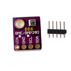
Among the numerous inexpensive BME280 break-out boards, we have chosen specifically this one, but plenty of others are available. The following details will work with any other BME280-based break-out board.

Connecting the I2C sensor

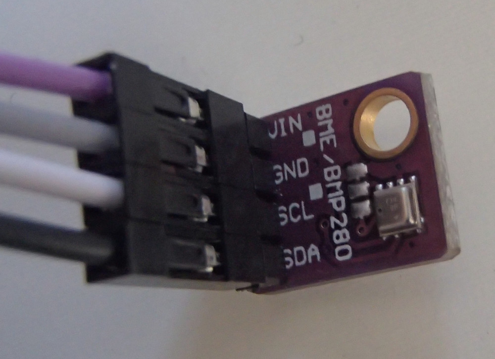
From a connectivity point of view, our I2C sensor is pretty simple: a VIN signal for power, a GND signal for ground, a SCL for the I2C clock and a SDA for the I2C data.

To understand how to connect this sensor to the Discovery board, we need to start with the board user manual.

The Discovery board has two main expansion connectors: CN2 and the Arduino connectors.

Connector CN2

Connector CN2 is a 40-pin male header on the front side of the board:

CN2 connector

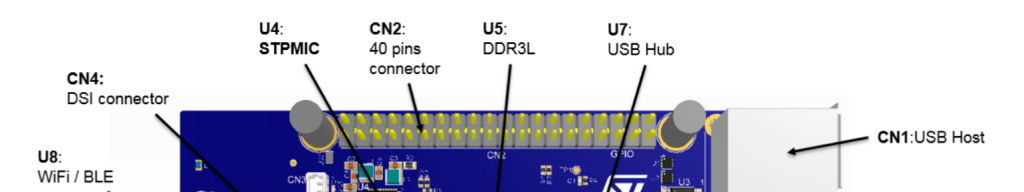
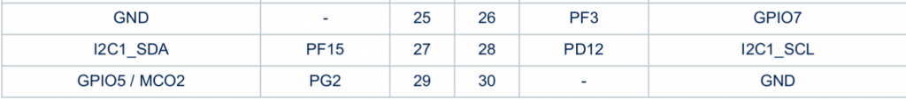
Section 7.17 of the board user manual documents the pin-out of this connector. There is one I2C bus available, through the I2C1_SDA (pin 27) and I2C1_SCL (pin 28) signals.

CN2 I2C1

Arduino connectors

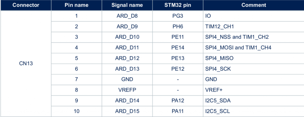
Connectors CN13, CN14, CN16, CN17 are female connectors on the back side of the board. They are compatible in pin-out and form-factor with the Arduino connector:

Arduino connectors

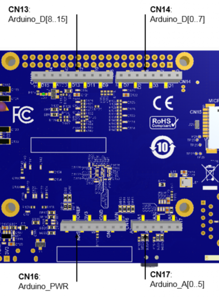
Section 7.16 of the board user manual documents the pin-out for these connectors. There is one I2C bus available as well in CN13, through the I2C5_SDA (pin 9) and I2C5_SCL (pin 10) signals.

CN13

Choosing the connector

According to the block diagram in Figure 3 of the board user manual, the I2C1 bus is already used to connect the touchscreen, the USB hub, the audio codec and the HDMI transceiver. However, I2C5 doesn’t seem to be used at all. In addition, with the screen mounted on the Discovery board, the CN2 connector is beneath the screen, which makes it a bit more difficult to use than the Arduino connectors on the back side.

We will therefore use the I2C5 bus, through the Arduino connector CN13. Pin 9 will be used to connect the data signal of our sensor, and pin 10 will be used to connect the clock signal of our sensor.

Finalizing the connectivity

We still have to find out how to connect the VIN and GND pins. According to the BME280 datasheet, VDDmain supply voltage range: 1.71V to 3.6V. The Arduino connector CN16 provides either 3.3V or 5V, so we’ll chose 3.3V (pin 4). And this connector also has multiple ground pins, among which we will chose pin 6.

Overall, this gives us the following connections:

Sensor signal Arduino connector Pin
VIN CN16 pin 4
GND CN16 pin 6
SDA CN13 pin 9
SCL CN13 pin 10

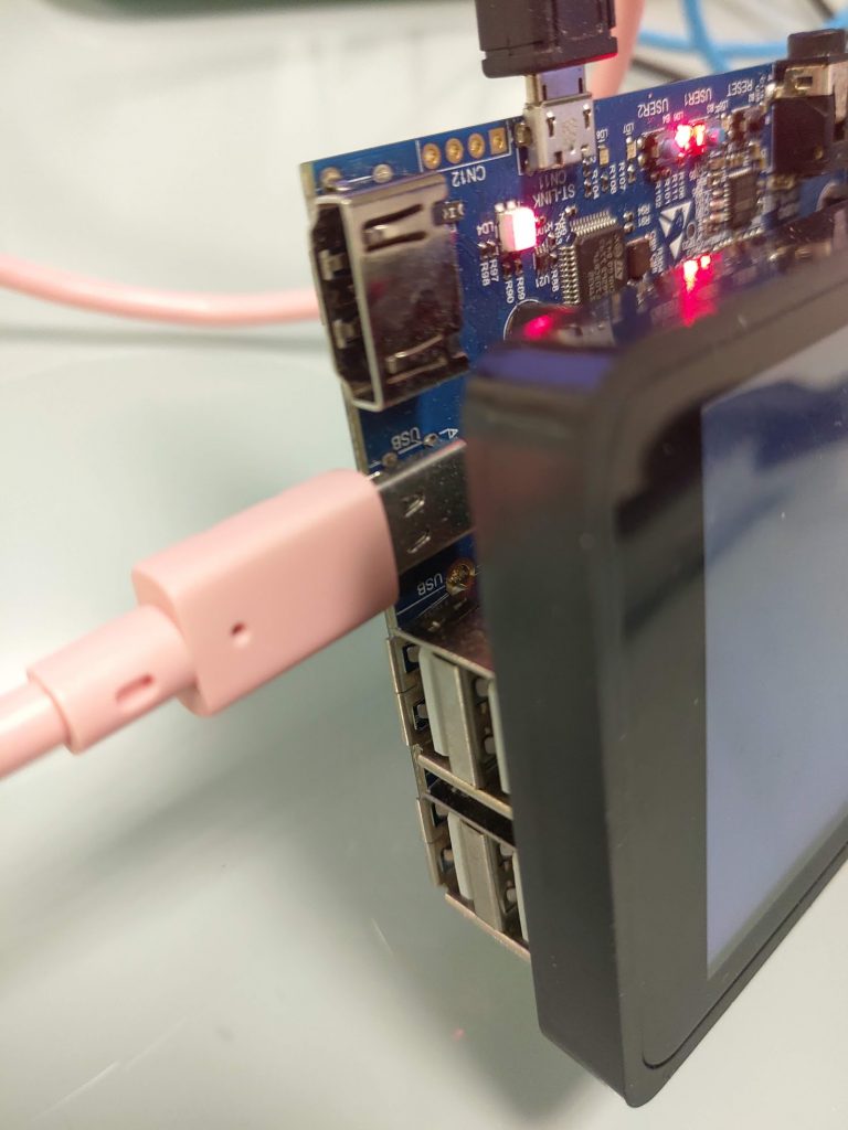
Here are a few pictures of the setup. First, on the sensor side, we have a purple wire for VIN, a grey wire for GND, a white wire for SCL and a black wire for SDA:

I2C sensor connection

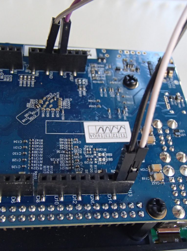
On the board side, we can see the purple wire (VIN) going to pin 4 of CN16, the grey wire (GND) going to pin 6 of CN16, the white wire (SCL) going to pin 10 of CN13 and the black wire (SDA) going to pin 9 of CN13.

I2C sensor connected to the board

With this we’re now all set in terms of hardware setup, let’s move on to enabling the I2C bus in Linux!

Enabling the I2C bus

An introduction to the Device Tree

In order to enable the I2C bus, we’ll need to modify the Device Tree, so we’ll first need to give a few details about what Device Tree is. If you read again our previous blog post in this series, we already mentioned the Device Tree. As part of the Buildroot build process, a file called stm32mp157c-dk2.dtb is produced, and this file is used at boot time by the Linux kernel: it is the Device Tree.

On most embedded architectures, devices are connected using buses that do not provide any dynamic enumeration capabilities. While buses like USB or PCI provide such capabilities, popular buses used on embedded architectures like memory-mapped buses, I2C, SPI and several others do not allow the operating system to ask the hardware: what peripherals are connected ? what are their characteristics ?. The operating system needs to know which devices are available and what their characteristics are. This is where the Device Tree comes into play: it is a data structure that describes in the form of a tree all the devices that we have in our hardware platform, so that the Linux kernel knows the topology of the hardware.

On ARM platforms, each particular board is described by its own Device Tree file. In our case, the STM32MP157 Discovery Kit 2 is described by the Device Tree file arch/arm/boot/dts/stm32mp157c-dk2.dts in the Linux kernel source code. This human-readable source file, with a .dts extension, is compiled during the Linux kernel build process into a machine-readable binary file, with a .dtb extension.

This stm32mp157c-dk2.dts describes the hardware of our Discovery Kit 2 platform. In fact, it only describes what is specific to the Discovery Kit 2: the display panel, the touchscreen, the WiFi and Bluetooth chip. Everything else is common with the Discovery Kit 1 platform, which is why the stm32mp157c-dk2.dts file includes the arm/boot/dts/stm32mp157a-dk1.dts file. Indeed, stm32mp157a-dk1.dts describes the hardware on the Discovery Kit 1, which is the same as the Discovery Kit 2, without the display, touchscreen and WiFi/Bluetooth chip.

In turn, the stm32mp157a-dk1.dts includes three other Device Tree files:

At this point, we won’t give much more generic details about the Device Tree, as it’s an entire topic on its own. For additional details, you could check the Device Tree for Dummies presentation from your author (slides, video) or the devicetree.org web site.

I2C controllers in the Device Tree

Zooming in to the topic of I2C, we can see that arm/boot/dts/stm32mp157c.dtsi describes 6 I2C controllers through six different nodes in the Device Tree:

  • i2c1: i2c@40012000
  • i2c2: i2c@40013000
  • i2c3: i2c@40014000
  • i2c4: i2c@5c002000
  • i2c5: i2c@40015000
  • i2c6: i2c@5c009000

This list of six I2C controllers nice matches the list of I2C controllers in the STM32MP157 datasheet, and their base address in the memory map, section 2.5.2:

I2C1I2C2I2C3I2C4I2C5I2C6

In the file arm/boot/dts/stm32mp157a-dk1.dts, we can see that the I2C1 bus is enabled, and that a cs42l51 audio codec (I2C address 0x4a) and a sii9022 HDMI transceiver (I2C address 0x39) are connected to it:

&i2c1 {
	status = "okay";

	cs42l51: cs42l51@4a {
		compatible = "cirrus,cs42l51";
		reg = <0x4a>;
	};

	hdmi-transmitter@39 {
		compatible = "sil,sii9022";
		reg = <0x39>;
	};
};

Also, on the I2C4 bus, we can see the USB-C controller (I2C address 0x28) and the PMIC (I2C address 0x33):

&i2c4 {
	status = "okay";

	typec: stusb1600@28 {
		compatible = "st,stusb1600";
		reg = <0x28>;
	};

	pmic: stpmic@33 {
		compatible = "st,stpmic1";
		reg = <0x33>;
	};
};

So, to enable our I2C5 bus, we will simply need to add:

&i2c5 {
	status = "okay";
	clock-frequency = <100000>;
	pinctrl-names = "default", "sleep";
	pinctrl-0 = <&i2c5_pins_a>;
	pinctrl-1 = <&i2c5_pins_sleep_a>;
};

to enable the bus. This piece of code adds the following Device Tree properties to the I2C5 Device Tree node:

  • status = "okay" which simply tells the Linux kernel: I really intend to use this device, so please enable whatever driver is needed to use this device
  • clock-frequency = <100000> tells Linux at which frequency we want to operate the I2C bus: in this case, 100 kHz
  • The pinctrl properties configure the pin muxing, so that the pins are configured in the I2C function when the system is running (the default state) and into a different state to preserve power when the system is in suspend to RAM (sleep state). Both i2c5_pins_a and i2c5_pins_sleep_a are already defined in arch/arm/boot/dts/stm32mp157-pinctrl.dtsi.

For now, this doesn’t describe any device on the bus, but should be sufficient to have the bus enabled in Linux. The question now is how to make this modification in our Device Tree in the proper way ?

Changing the Linux kernel source code

When Buildroot builds each package, it extracts its source code in output/build/<package>-<version>, so the source code of our Linux kernel has been extracted in output/build/linux-custom/. One could therefore be tempted to make his code changes directory in output/build/linux-custom/, but this has a number of major drawbacks:

  1. output/build/linux-custom/ is not under version control: it is not part of a Linux kernel Git repository, so you can’t version control your changes, which is really not great
  2. output/build/linux-custom/ is a temporary folder: if you do a make clean in Buildroot, this folder will be entirely removed, and re-created during the next Buildroot build

So, while doing a change directly in output/build/linux-custom/ is perfectly fine for quick/temporary changes, it’s not a good option to make changes that will be permanent.

To do this in a proper way, we will use a feature of Buildroot called pkg_OVERRIDE_SRCDIR, which is documented in section 8.12.6 Using Buildroot during development of the Buildroot manual. This feature allows to tell Buildroot: for a given package, please don’t download it from the usual location, but instead take the source code from a specific location on my system. This specific location will of course be under version control, and located outside of Buildroot, which allows to solve the two issues mentioned above.

So, let’s get set this up for the Linux kernel source code:

  1. Start in the parent folder of Buildroot, so that the Linux kernel source code ends up being side-by-side with Buildroot
  2. Clone the official upstream Linux kernel repository. Even though we could directly clone the STMicro Linux kernel repository, your author always finds it nicer to have the origin Git remote set up to the official upstream Git repository.
    git clone git://git.kernel.org/pub/scm/linux/kernel/git/torvalds/linux.git
    
  3. Move inside this Git repository
    cd linux/
    
  4. Add the STMicro Linux kernel repository as a remote:
    git remote add stmicro https://github.com/STMicroelectronics/linux.git
    
  5. Fetch all the changes from the STMicro Linux kernel repository:
    git fetch stmicro
    
  6. Create a new branch, called bme280, based on the tag v4.19-stm32mp-r1.2. This tag is the one used by our Buildroot configuration as the version of the Linux kernel. The following command also moves to this new branch as the same time:
    git checkout -b bme280 v4.19-stm32mp-r1.2
    
  7. At this point, our linux/ folder contains the exact same source code as what Buildroot has retrieved. It is time to make our Device Tree change by editing arch/arm/boot/dts/stm32mp157c-dk2.dts and at the end of it, add:

    &i2c5 {
    	status = "okay";
    	clock-frequency = <100000>;
    	pinctrl-names = "default", "sleep";
    	pinctrl-0 = <&i2c5_pins_a>;
    	pinctrl-1 = <&i2c5_pins_sleep_a>;
    };
    

    Once done, we need to tell Buildroot to use our kernel source code, using the pkg_OVERRIDE_SRCDIR mechanism. To this, create a file called local.mk, in the top-level Buildroot source directory, which contains:

    LINUX_OVERRIDE_SRCDIR = $(TOPDIR)/../linux
    

    This tells Buildroot to pick the Linux kernel source from $(TOPDIR)/../linux. We’ll now ask Buildroot to wipe out its Linux kernel build, and do a build again:

    $ make linux-dirclean
    $ make
    

    If you look closely at what Buildroot will do, it will do a rsync of the Linux kernel source code from your linux/ Git repository to output/build/linux-custom in Buildroot, and then do the build. You can check output/build/linux-custom/arch/arm/boot/dts/stm32mp157c-dk2.dts to make sure that your I2C5 change is there!

    If that is the case, then reflash output/images/sdcard.img on your SD card, and run the new system on the board. It’s now time to test the I2C bus!

    Testing the I2C bus

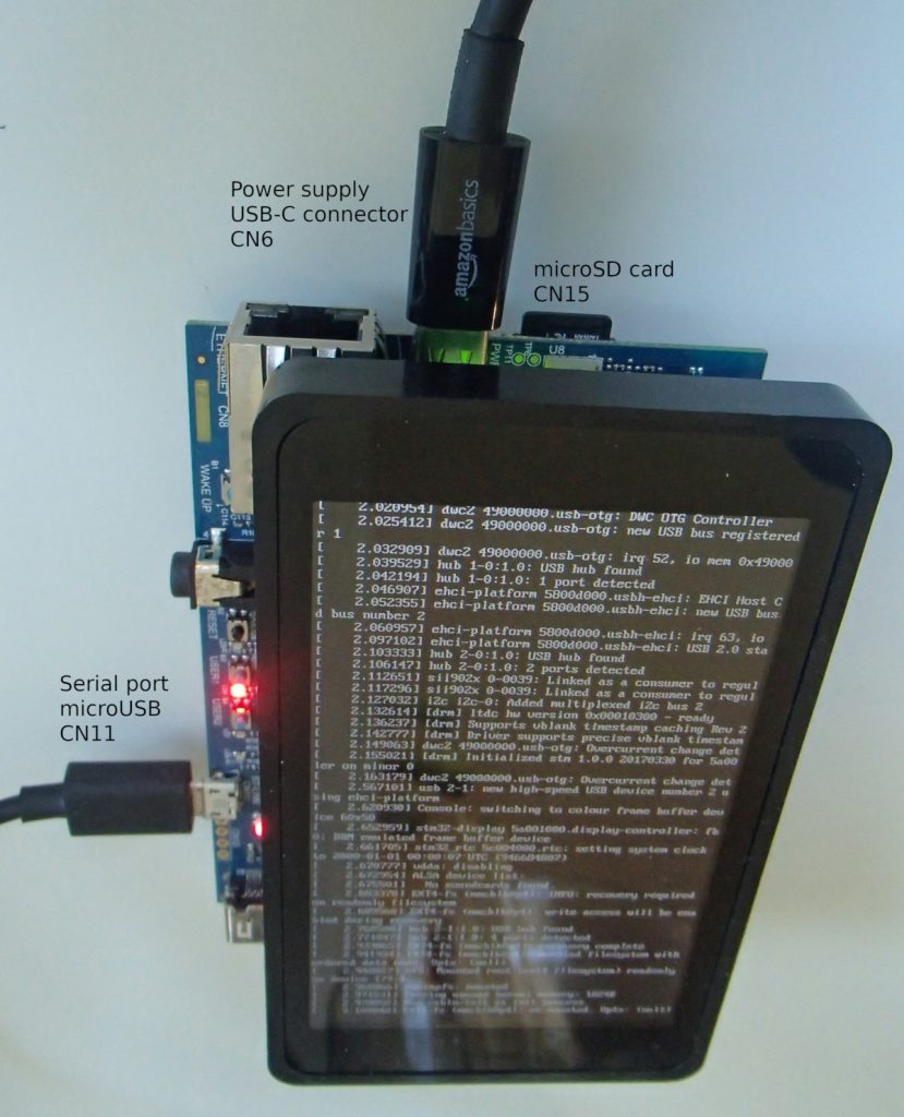
    After booting the new system on your Discovery board and logging in as root, let’s have a look at all I2C related devices:

    # ls -l /sys/bus/i2c/devices/
    total 0
    lrwxrwxrwx    0-002a -> ../../../devices/platform/soc/40012000.i2c/i2c-0/0-002a
    lrwxrwxrwx    0-0038 -> ../../../devices/platform/soc/40012000.i2c/i2c-0/0-0038
    lrwxrwxrwx    0-0039 -> ../../../devices/platform/soc/40012000.i2c/i2c-0/0-0039
    lrwxrwxrwx    0-004a -> ../../../devices/platform/soc/40012000.i2c/i2c-0/0-004a
    lrwxrwxrwx    2-0028 -> ../../../devices/platform/soc/5c002000.i2c/i2c-2/2-0028
    lrwxrwxrwx    2-0033 -> ../../../devices/platform/soc/5c002000.i2c/i2c-2/2-0033
    lrwxrwxrwx    i2c-0 -> ../../../devices/platform/soc/40012000.i2c/i2c-0
    lrwxrwxrwx    i2c-1 -> ../../../devices/platform/soc/40015000.i2c/i2c-1
    lrwxrwxrwx    i2c-2 -> ../../../devices/platform/soc/5c002000.i2c/i2c-2
    lrwxrwxrwx    i2c-3 -> ../../../devices/platform/soc/40012000.i2c/i2c-0/i2c-3
    

    This folder is part of the sysfs filesystem, which is used by the Linux kernel to expose to user-space applications all sort of details about the hardware devices connected to the system. More specifically, in this folder, we have symbolic links for two types of devices:

    • The I2C busses: i2c-0, i2c-1, i2c-2 and i2c-3. It is worth mentioning that the bus numbers do not match the datasheet: they are simply numbered from 0 to N. However, the i2c-0 symbolic link shows it’s the I2C controller at base address 0x40012000, so it’s I2C1 in the datasheet, i2c-1 is at base address 0x40015000 so it’s I2C5 in the datasheet, and i2c-2 at base address 0x5c002000 is I2C4 in the datasheet. i2c-3 is special as it’s not an I2C bus provided by the SoC itself, but the I2C bus provided by the HDMI transmitter to talk with the remote HDMI device (since this is unrelated to our discussion, we won’t go into more details on this).
    • The I2C devices: 0-002a, 0-0038, 0-0039, 0-004a, 2-0028, 2-033. These entries have the form B-SSSS where B is the bus number and SSSS is the I2C address of the device. So you can see that for example 0-004a corresponds to the cs42l51 audio codec we mentioned earlier.

    In our case, we are interested by I2C5, which is known by Linux as i2c-1. We will use the i2cdetect utility, provided by Busybox, to probe the different devices on this bus:

    # i2cdetect -y 1
         0  1  2  3  4  5  6  7  8  9  a  b  c  d  e  f
    00:          -- -- -- -- -- -- -- -- -- -- -- -- -- 
    10: -- -- -- -- -- -- -- -- -- -- -- -- -- -- -- -- 
    20: -- -- -- -- -- -- -- -- -- -- -- -- -- -- -- -- 
    30: -- -- -- -- -- -- -- -- -- -- -- -- -- -- -- -- 
    40: -- -- -- -- -- -- -- -- -- -- -- -- -- -- -- -- 
    50: -- -- -- -- -- -- -- -- -- -- -- -- -- -- -- -- 
    60: -- -- -- -- -- -- -- -- -- -- -- -- -- -- -- -- 
    70: -- -- -- -- -- -- 76 --                         
    

    Interesting, we have a device at address 0x76! Try to disconnect VIN of your I2C sensor, and repeat the command:

    # i2cdetect -y 1
         0  1  2  3  4  5  6  7  8  9  a  b  c  d  e  f
    00:          -- -- -- -- -- -- -- -- -- -- -- -- -- 
    10: -- -- -- -- -- -- -- -- -- -- -- -- -- -- -- -- 
    20: -- -- -- -- -- -- -- -- -- -- -- -- -- -- -- -- 
    30: -- -- -- -- -- -- -- -- -- -- -- -- -- -- -- -- 
    40: -- -- -- -- -- -- -- -- -- -- -- -- -- -- -- -- 
    50: -- -- -- -- -- -- -- -- -- -- -- -- -- -- -- -- 
    60: -- -- -- -- -- -- -- -- -- -- -- -- -- -- -- -- 
    70: -- -- -- -- -- -- -- --                         
    

    The device at 0x76 has disappeared, so it looks like our sensor is at I2C address 0x76. To confirm this, let’s have a look at what the BME280 datasheet says about the I2C address of the device, in section 6.2 I2C Interface:

    BME280 I2C address

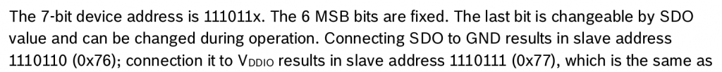
    So, the I2C address is indeed 0x76 when the SDO pin of the sensor is connected to GND, which is probably what our BME280 break-out board is doing. It matches the address we have detected with i2cdetect!

    Now, let’s talk to our device. According to section 5.4 Register description of the datasheet, there is a Chip ID register, at offset 0xD0 that is supposed to contain 0x60:

    BME280 Chip ID

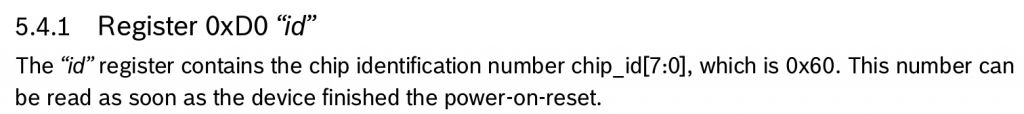
    We can read this register using the i2cget command:

    # i2cget -y 1 0x76 0xd0
    0x60
    

    Good, this matches the expected value according to the BME280 datasheet, so it seems like communication with our I2C device is working, let’s move on to enabling the BME280 sensor driver.

    Enabling the sensor driver

    As discussed earlier, this BME280 sensor already has a driver in the upstream Linux kernel, in the IIO subsystem. IIO stands for Industrial Input/Output, and this subsystems contains a lot of drivers for various ADCs, sensors and other types of measurement/acquisition devices. In order to use this driver for our BME280 device, we will essentially have to do two things:

    1. Enable the driver in our Linux kernel configuration, so that the driver code gets built as part of our kernel image
    2. Describe the BME280 device in our Device Tree so that the Linux kernel knows we have one such device, and how it is connected to the system

    Adjusting the kernel configuration

    In the previous blog post, we explained that the Linux kernel configuration used to build the kernel for the STM32 Discovery board was located at board/stmicroelectronics/stm32mp157-dk/linux.config. Obviously, we are not going to edit this file manually: we need to run the standard Linux kernel configuration tools.

    It turns out that Buildroot has convenient shortcuts to manipulate the Linux kernel configuration. We can run the Linux kernel menuconfig configuration tool by running:

    $ make linux-menuconfig
    

    At this point, it is really important to not be confused by the fact that both Buildroot and the Linux kernel use the same configuration utility, but each have its own configuration. The Buildroot configuration describes your overall system (target architecture, which software components you want, which type of filesystem you want, etc.) while the Linux kernel configuration describes the kernel configuration itself (which drivers you want, which kernel features you need, etc.). So make sure to not confuse the menuconfig of Buildroot with the menuconfig of the Linux kernel!

    Once you have run make linux-menuconfig, the menuconfig of the Linux kernel will show up. You will then enable the following option:

    Device Drivers
    +- Industrial I/O support
       +- Pressure sensors
          +- Bosch Sensortec BMP180/BMP280 pressure sensor I2C driver
    

    Make sure to enable this option with a star <*> so that the driver is compiled inside the kernel image itself and not as a separate kernel module. You can then exit the menuconfig utility, and confirm that you want to save the configuration.

    At this point, the Linux kernel configuration file in output/build/linux-custom/.config has been changed. You can confirm it by running:

    $ grep CONFIG_BMP280 output/build/linux-custom/.config
    CONFIG_BMP280=y
    CONFIG_BMP280_I2C=y
    CONFIG_BMP280_SPI=y
    

    However, as we explained earlier, the output/build/linux-custom/ folder is temporary: it would be removed when doing a Buildroot make clean. We would like to permanently keep our Linux kernel configuration. Once again, Buildroot provides a nice shortcut to do this:

    $ make linux-update-defconfig
    

    After running this command, the kernel configuration file board/stmicroelectronics/stm32mp157-dk/linux.config has been updated, and this file is not temporary, and is under version control. If you run git diff, you can see the change on this file:

    $ git diff
    [...]
    index 878a0c39f1..12f3e22647 100644
    --- a/board/stmicroelectronics/stm32mp157-dk/linux.config
    +++ b/board/stmicroelectronics/stm32mp157-dk/linux.config
    @@ -169,6 +169,7 @@ CONFIG_STM32_LPTIMER_CNT=y
     CONFIG_STM32_DAC=y
     CONFIG_IIO_HRTIMER_TRIGGER=y
     CONFIG_IIO_STM32_LPTIMER_TRIGGER=y
    +CONFIG_BMP280=y
     CONFIG_PWM=y
     CONFIG_PWM_STM32=y
     CONFIG_PWM_STM32_LP=y
    

    We’re all set for the kernel configuration!

    Describing the BME280 in the Device Tree

    We now need to tell the Linux kernel that we have a BME280 sensor and how it is connected to the system, which is done by adding more details into our Device Tree. We have already enabled the I2C5 bus, and we now need to describe one device connected to it: this gets done by creating a child node of the I2C controller node.

    How do we know what to write in the Device Tree node describing the BME280 ? Using Device Tree bindings. Those bindings are specification documents that describe how a given device should be represented in the Device Tree: which properties are available, what are their possible values, etc. All Device Tree bindings supported by the Linux kernel are documented in Documentation/devicetree/bindings in the Linux kernel source code. For our BME280 device, the binding is at Documentation/devicetree/bindings/iio/pressure/bmp085.yaml.

    This document tells us that we have one required property, the compatible property, with the range of possible values. Since we have a BME280 sensor, we’ll use bosch,bme280. The other properties are optional, so we’ll ignore them for now. This binding also documents a reg property, which is used to provide to the Linux kernel the I2C address of the device.

    So, we’ll go back to our linux/ directory outside of Buildroot, where we cloned the Linux kernel repository, and we’ll adjust our Device Tree file arch/arm/boot/dts/stm32mp157c-dk2.dts so that it contains:

    &i2c5 {
    	status = "okay";
    	clock-frequency = <100000>;
    	pinctrl-names = "default", "sleep";
    	pinctrl-0 = <&i2c5_pins_a>;
    	pinctrl-1 = <&i2c5_pins_sleep_a>;
    
    	pressure@76 {
    		compatible = "bosch,bme280";
    		reg = <0x76>;
    	};
    };
    

    Re-building the kernel

    Let’s now ask Buildroot to rebuild the Linux kernel, with our Device Tree change and kernel configuration change. Instead of rebuilding from scratch, we’ll just ask Buildroot to restart the build of the Linux kernel, which will be much faster:

    $ make linux-rebuild
    

    As part of this, Buildroot will re-run rsync from our linux/ kernel Git repository to output/build/linux-custom/, so that we really build the latest version of our code, which includes our Device Tree change.

    However, this just rebuilds the Linux kernel, and not the complete SD card image, so also run:

    $ make
    

    To regenerate the SD card image, write it on your SD card, and boot your system.

    Testing the sensor

    After booting the system, if we check /sys/bus/i2c/devices, a new entry has appeared:

    lrwxrwxrwx    1-0076 -> ../../../devices/platform/soc/40015000.i2c/i2c-1/1-0076
    

    If we following this symbolic link, we can see a number of interesting information:

    # ls -l /sys/bus/i2c/devices/1-0076/
    total 0
    lrwxrwxrwx    driver -> ../../../../../../bus/i2c/drivers/bmp280
    drwxr-xr-x    iio:device2
    -r--r--r--    modalias
    -r--r--r--    name
    lrwxrwxrwx    of_node -> ../../../../../../firmware/devicetree/base/soc/i2c@40015000/pressure@76
    drwxr-xr-x    power
    lrwxrwxrwx    subsystem -> ../../../../../../bus/i2c
    -rw-r--r--    uevent
    

    Here we can see that this device is bound with the device driver named bmp280, and that its Device Tree node is base/soc/i2c@40015000/pressure@76.

    Now, to actually use the sensor, we need to understand what is the user-space interface provided by IIO devices. The kernel documentation gives some hints:

    There are two ways for a user space application to interact with an IIO driver.

    • /sys/bus/iio/iio:deviceX/, this represents a hardware sensor and groups together the data channels of the same chip.
    • /dev/iio:deviceX, character device node interface used for buffered data transfer and for events information retrieval.

    So, we’ll try to explore the /sys/bus/iio/ option:

    # ls -l /sys/bus/iio/devices/
    total 0
    lrwxrwxrwx    iio:device0 -> ../../../devices/platform/soc/48003000.adc/48003000.adc:adc@0/iio:device0
    lrwxrwxrwx    iio:device1 -> ../../../devices/platform/soc/48003000.adc/48003000.adc:adc@100/iio:device1
    lrwxrwxrwx    iio:device2 -> ../../../devices/platform/soc/40015000.i2c/i2c-1/1-0076/iio:device2
    lrwxrwxrwx    iio:device3 -> ../../../devices/platform/soc/48003000.adc/48003000.adc:temp/iio:device3
    lrwxrwxrwx    trigger0 -> ../../../devices/platform/soc/40004000.timer/trigger0
    

    Here we can see a number of IIO devices: our IIO device is iio:device2, as can be seen by looking at the target of the symbolic links. The other ones are IIO devices related to the ADC on the STM32 processor. Let’s check what we have inside /sys/bus/iio/devices/iio:device2/:

    # ls -l /sys/bus/iio/devices/iio\:device2/
    total 0
    -r--r--r--    dev
    -rw-r--r--    in_humidityrelative_input
    -rw-r--r--    in_humidityrelative_oversampling_ratio
    -rw-r--r--    in_pressure_input
    -rw-r--r--    in_pressure_oversampling_ratio
    -r--r--r--    in_pressure_oversampling_ratio_available
    -rw-r--r--    in_temp_input
    -rw-r--r--    in_temp_oversampling_ratio
    -r--r--r--    in_temp_oversampling_ratio_available
    -r--r--r--    name
    lrwxrwxrwx    of_node -> ../../../../../../../firmware/devicetree/base/soc/i2c@40015000/pressure@76
    drwxr-xr-x    power
    lrwxrwxrwx    subsystem -> ../../../../../../../bus/iio
    -rw-r--r--    uevent
    

    This is becoming interesting! We have a number of files that we can read to get the humidity, pressure, and temperature:

    # cat /sys/bus/iio/devices/iio\:device2/in_humidityrelative_input 
    49147
    # cat /sys/bus/iio/devices/iio\:device2/in_pressure_input 
    101.567167968
    # cat /sys/bus/iio/devices/iio\:device2/in_temp_input 
    24380
    

    Now, let’s check the kernel documentation at Documentation/ABI/testing/sysfs-bus-iio to understand the units used in these files:

    What:		/sys/bus/iio/devices/iio:deviceX/in_tempX_input
    Description:
    		Scaled temperature measurement in milli degrees Celsius.
    
    What:		/sys/bus/iio/devices/iio:deviceX/in_pressure_input
    Description:
    		Scaled pressure measurement from channel Y, in kilopascal.
    
    What:		/sys/bus/iio/devices/iio:deviceX/in_humidityrelative_input
    Description:
    		Scaled humidity measurement in milli percent.
    

    So here we are: we are able to read the data from our sensor, and the Linux kernel driver does all the conversion work to convert the raw values from the sensors into usable values in meaningful units.

    Turning our kernel change into a patch

    Our Device Tree change is for now only located in our local Linux kernel Git repository: if another person builds our Buildroot configuration, he won’t have access to this Linux kernel Git repository, which Buildroot knows about thanks to the LINUX_OVERRIDE_SRCDIR variable. So what we’ll do now is to generate a Linux kernel patch that contains our Device Tree change, add it to Buildroot, and ask Buildroot to apply it when building the Linux kernel. Let’s get started.

    First, go in your Linux kernel Git repository in linux/, review your Device Tree change with git diff, and if everything is alright, make a commit out of it:

    $ git commit -as -m "ARM: dts: add support for BME280 sensor on STM32MP157 DK2"
    

    Then, generate a patch out of this commit:

    $ git format-patch HEAD^
    

    This will create a file called 0001-ARM-dts-add-support-for-BME280-sensor-on-STM32MP157-.patch that contains our Device Tree change.

    Now, back in Buildroot in the buildroot/ folder, create the board/stmicroelectronics/stm32mp157-dk/patches/ folder and a sub-directory board/stmicroelectronics/stm32mp157-dk/patches/linux. Copy the patch into this folder, so that the file hierarchy looks like this:

    $ tree board/stmicroelectronics/stm32mp157-dk/
    board/stmicroelectronics/stm32mp157-dk/
    ├── genimage.cfg
    ├── linux.config
    ├── overlay
    │   └── boot
    │       └── extlinux
    │           └── extlinux.conf
    ├── patches
    │   └── linux
    │       └── 0001-ARM-dts-add-support-for-BME280-sensor-on-STM32MP157-.patch
    ├── readme.txt
    └── uboot-fragment.config
    

    Now, run Buildroot’s menuconfig:

    $ make menuconfig
    

    And in Build options, set global patch directories to the value board/stmicroelectronics/stm32mp157-dk/patches/. This tells Buildroot to apply patches located in this folder whenever building packages. This way, when the linux package will be built, our patch in board/stmicroelectronics/stm32mp157-dk/patches/linux/ will be applied.

    We can now remove the local.mk file to disable the pkg_OVERRIDE_SRCDIR mechanism, and ask Buildroot to rebuild the Linux kernel:

    $ rm local.mk
    $ make linux-dirclean
    $ make
    

    If you pay attention to the Linux kernel build process, you will see that during the Patching step, our Device Tree patch gets applied:

    >>> linux custom Patching
    
    Applying 0001-ARM-dts-add-support-for-BME280-sensor-on-STM32MP157-.patch using patch: 
    patching file arch/arm/boot/dts/stm32mp157c-dk2.dts
    

    You can of course reflash the SD card at the end of the build, and verify that everything still works as expected.

    Let’s save our Buildroot configuration change:

    $ make savedefconfig
    

    And commit our Buildroot changes:

    $ git add board/stmicroelectronics/stm32mp157-dk/linux.config
    $ git add board/stmicroelectronics/stm32mp157-dk/patches/
    $ git add configs/stm32mp157_dk_defconfig
    $ git commit -s -m "configs/stm32mp157_dk: enable support for BME280 sensor"
    

    We can now share our Buildroot change with others: they can build our improved system which has support for the BME280 sensor.

    Conclusion

    You can find the exact Buildroot source code used to reproduce the system used in this article in the branch at 2019.02/stm32mp157-dk-blog-2.

    In this article, we have learned a lot of things:

    • How to connect an I2C sensor to the Discovery board
    • What is the Device Tree, and how it is used to describe devices
    • How to use Buildroot’s pkg_OVERRIDE_SRCDIR mechanism
    • How to enable the I2C bus in the Device Tree and test its operation using i2cdetect and i2cget
    • How to change the Linux kernel configuration to enable a new driver
    • How to interact using sysfs with a sensor supported by the IIO subsystem
    • How to generate a Linux kernel patch, and add it into Buildroot

    In our next article, we’ll look at adding support for the Qt5 graphical library into our system, as a preparation to developing a Qt5 application that will display our sensor measurements on the Discovery board screen.

Building a Linux system for the STM32MP1: basic system

As we announced recently, we are going to publish a series of blost post that describes how to build an embedded Linux device based on the STM32MP1 platform, using the Buildroot build system. In this first article, we are going to see how to create a basic Linux system, with minimal functionality. The hardware platform used in these articles is the STM32MP157-DK2.

List of articles in this series:

  1. Building a Linux system for the STM32MP1: basic system
  2. Building a Linux system for the STM32MP1: connecting an I2C sensor
  3. Building a Linux system for the STM32MP1: enabling Qt5 for graphical applications
  4. Building a Linux system for the STM32MP1: setting up a Qt5 application development environment
  5. Building a Linux system for the STM32MP1: developing a Qt5 graphical application
  6. Building a Linux system for the STM32MP1: implementing factory flashing
  7. Building a Linux system for the STM32MP1: remote firmware updates

What is Buildroot?

A Linux system is composed of a potentially large number of software components coming from different sources:

  • A bootloader, typically U-Boot, responsible for doing some minimal HW initialization, loading the Linux kernel and starting it
  • The Linux kernel itself, which implements features such as process management, memory management, scheduler, filesystems, networking stack and of course all device drivers for your hardware platform
  • User-space libraries and applications coming from the open-source community: command line tools, graphical libraries, networking libraries, cryptographic libraries, and more.
  • User-space libraries and applications developed internally, implementing the “business logic” of the embedded system

In order to assemble a Linux system with all those software components, one typically has two main choices:

  • Use a binary distribution, like Debian, Ubuntu or Fedora. Several of these distributions have support for the ARMv7 architecture. The main advantage of this solution is that it is easy: these binary distributions are familiar to most Linux users, they have a nice and easy-to-use package management system, all packages are pre-compiled so it is really fast to generate a Linux system. However, Linux systems generated this way are typically difficult to customize (software components are pre-built, so you cannot easily tweak their configuration to your needs) and difficult to optimize (in terms of footprint or boot time).
  • Use a build system, like Buildroot or Yocto/OpenEmbedded. These build systems build an entire Linux system from source code, which means that it can be highly customized and optimized to your needs. Of course, it is less simple than using a binary distribution and because you are building all components from source code, a non-negligible amount of CPU time will be spent on compiling code.

BuildrootIn this series of blog post, we have chosen to use Buildroot, which is an easy-to-use build system, which is a good match for engineers getting started with embedded Linux. For more general details about Buildroot, you can read the freely available training materials of our Embedded Linux development with Buildroot training course.

Buildroot is a set of Makefiles and script that automates the process of download the source code of the different software components, extract them, configure them, build them and install them. It ultimately generates a system image that is ready to be flashed, and which typically contains the bootloader, the Linux kernel image and the root filesystem. It is important to understand that Buildroot itself does not contain the source code for Linux, U-Boot or any other component: it is only a set of scripts/recipes that describes where to download the source code from, and how to build it.

Principle of an embedded Linux build system

Building the minimal system with Buildroot

Let’s started by getting the source of Buildroot from its upstream Git repository:

git clone git://git.buildroot.net/buildroot
cd buildroot

Starting a Buildroot configuration is then typically done by running make menuconfig, and then selecting all the relevant options for your system. Here, we are instead going to use a pre-defined configuration that we created for the STM32MP157-DK2 platform. This pre-defined configuration has been submitted to the upstream Buildroot project, but has not yet been merged as of this writing, so we’ll use an alternate Git branch:

git remote add tpetazzoni https://github.com/tpetazzoni/buildroot.git
git fetch tpetazzoni
git checkout -b stm32mp157-dk2 tpetazzoni/2019.02/stm32mp157-dk

The 2019.02/stm32mp157-dk branch in your author’s Buildroot Git repository is based on upstream Buildroot 2019.02.x branch and contains 4 additional patches needed to support the STM32MP157-DK2 platform.

Let’s continue by telling Buildroot to load the pre-defined configuration for the STM32MP157-DK2:

make stm32mp157_dk_defconfig

We could start the build right away, as this configuration works fine, but to illustrate how to modify the configuration (and speed up the build!) we will adjust one aspect of the system configuration. To do so, let’s run Buildroot’s menuconfig. People who have already configured the Linux kernel should be familiar with the tool, as it is the exact same configuration utility.

make menuconfig

At this point, if the command fails due to the ncurses library being missing, make sure to install the libcnurses-dev or ncurses-devel package on your Linux distribution (the exact package name depends on the distribution you’re using).

Once in menuconfig, go to the Toolchain sub-menu. By default the Toolchain type is Buildroot toolchain. Change it to External toolchain by pressing the Enter key. When Buildroot toolchain is selected, Buildroot builds its own cross-compiler, which takes quite some time. Selecting External toolchain tells Buildroot to use a pre-existing cross-compiler, which in our case is the one provided by ARM for the ARMv7 architecture.

Exit menuconfig and save the configuration. It is now time to start the build by running make. However, your author generally likes to keep the output of the build in a log file, using the following incantation:

make 2>&1 | tee build.log

Now that Buildroot starts by checking if your system has a number of required packages installed, and will abort if not. Please follow section System requirements > Mandatory packages of the Buildroot manual to install all the appropriate dependencies. Restart the make command once all dependencies have been installed.

The build process took 10 minutes on your author’s machine. All the build output is conveniently grouped in the sub-directory named output/, in which the most important results are in output/images/:

  • output/images/zImage is the Linux kernel image
  • output/images/stm32mp157c-dk2.dtb is the Device Tree Blob, i.e the piece of data that describes to the Linux kernel the hardware it is running on. We’ll talk more about Device Tree in the second blog post of this series
  • output/images/rootfs.{ext4,ext2} is the image of the root filesystem, i.e the filesystem that contains all the user-space libraries and applications. It’s using the ext4 filesystem format, which is the de-facto standard filesystem format in Linux for block storage.
  • output/images/u-boot-spl.stm32 is the first stage bootloader
  • output/images/u-boot.img is the second stage bootloader
  • output/images/sdcard.img is a complete, ready-to-use SD card image, which was generated from the previous images

Flashing and testing the system

First things first, we’ll need to write sdcard.img to a microSD card:

sudo dd if=output/images/sdcard.img of=/dev/mmcblk0 bs=1M conv=fdatasync status=progress

Of course, make sure that, on your system, the microSD card is really identified as /dev/mmcblk0. And beware that all the data on your microSD card will be lost!

Insert the microSD card in the microSD card connector of the STM32MP157-DK2 board, i.e connector CN15.

Connect a USB to micro-USB cable between your PC and the connector labeled ST-LINK CN11 on the board. A device called /dev/ttyACM0 will appear on your PC, through which you’ll be able to access the board’s serial port. Install and run a serial port communication program on your PC, your author’s favorite is the very minimalistic picocom:

picocom -b 115200 /dev/ttyACM0

Finally, power up the board by connecting a USB-C cable to connector PWR_IN CN6. You should then see a number of messages on the serial port, all the way up to Buildroot login:. You can then login with the root user, no password will be requested.

STM32MP157-DK2 in situation

How is the system booting ?

Let’s look at the main steps of the boot process, by studying the boot log visible on the serial port:

U-Boot SPL 2018.11-stm32mp-r2.1 (Apr 24 2019 - 10:37:17 +0200)

This message is printed by the first stage bootloader, i.e the code contained in the file u-boot-spl.stm32, compiled as part of the U-Boot bootloader. This first stage bootloader is directly loaded by the STM32MP157 system-on-chip. This first stage bootloader must be small enough to fit inside the STM32MP157 internal memory.

U-Boot 2018.11-stm32mp-r2.1 (Apr 24 2019 - 10:37:17 +0200)

This message is printed by the second stage bootloader, which was loaded from storage into external memory by the first stage bootloader. This second stage bootloader is the file u-boot.img, which was also compiled as part of the U-Boot bootloader.

Retrieving file: /boot/zImage
Retrieving file: /boot/stm32mp157c-dk2.dtb

These messages are printed by the second stage bootloader: we see it is loading the Linux kernel image (file zImage) and the Device Tree Blob describing our hardware platform (file stm32mp157c-dk2.dtb). It indicates that U-Boot has loaded both files into memory: it is now ready to start the Linux kernel.

Starting kernel ...

This is the last message printed by U-Boot before jumping into the kernel.

[    0.000000] Booting Linux on physical CPU 0x0
[    0.000000] Linux version 4.19.26 (thomas@windsurf) (gcc version 8.2.1 20180802 (GNU Toolchain for the A-profile Architecture 8.2-2018.11 (arm-rel-8.26))) #1 SMP PREEMPT Wed Apr 24 10:38:00 CEST 2019

And immediately after that, we have the first messages of the Linux kernel, showing the version of Linux and the date/time it was built. Numerous other kernel messages are then displayed, until:

[    3.248315] VFS: Mounted root (ext4 filesystem) readonly on device 179:4.

This message indicates that the kernel has mounted the root filesystem. After this point, the kernel will start the first user-space process, so the next messages are user-space services being initialized:

Starting syslogd: OK
[...]
Welcome to Buildroot
buildroot login: 

Until we reach a login prompt.

Exploring the system

After logging in as root, you have access to a regular Linux shell, with most basic Linux commands available. You can run ps to see the processes, run ls / to see the contents of the root filesystem, etc.

You can also play a bit with the hardware, for example to turn on and off one of the LEDs of the board:

echo 255 > /sys/class/leds/heartbeat/brightness
echo 0 > /sys/class/leds/heartbeat/brightness

Understanding the Buildroot configuration

So far, we have used a pre-defined Buildroot configuration, without really understanding what it does and how it built this basic system for our board. So let’s go back in make menuconfig and see how Buildroot was configured.

In the Target options menu, obviously the ARM Little Endian architecture was chosen, and more specifically Cortex-A7 was chosen as the Target Architecture Variant. Indeed the entire Linux system runs on the Cortex-A7 cores.

In the Build options menu, nothing was changed from the default values.

In the Toolchain menu, we previously modified to use an External toolchain to use a pre-existing cross-compiler and save on build time. All other options were kept as their default.

In the System configuration menu, we defined the following things:

  • Root filesystem overlay directories is set to board/stmicroelectronics/stm32mp157-dk/overlay/. This option tells Buildroot that the contents of the board/stmicroelectronics/stm32mp157-dk/overlay/ directory must be copied into the root filesystem at the end of the build. It allows to add custom files to the root filesystem.
  • Custom scripts to run after creating filesystem images is set to support/scripts/genimage.sh and the related option Extra arguments passed to custom scripts is set to -c board/stmicroelectronics/stm32mp157-dk/genimage.cfg. This tells Buildroot to call this genimage.sh script at the very end of the build: its purpose is to generate the final SD card image we have used.

In the Kernel menu, we have obviously configured which Linux kernel version and configuration should be used:

  • We are downloading the Linux kernel source code as a tarball from Github, using a custom Buildroot macro called github. Based on this information, Buildroot will go to the Git repository at https://github.com/STMicroelectronics/linux/, and get the kernel version identified by the tag v4.19-stm32mp-r1.2
  • Configuration file path is set to board/stmicroelectronics/stm32mp157-dk/linux.config. This is the file that contains the kernel configuration. We have prepared a custom kernel configuration to have a simple but working kernel configuration. Of course, it can be adjusted to your needs, as we will demonstrate in the next blog post.
  • We enabled the option Build a Device Tree Blob (DTB) and set In-tree Device Tree Source file names to stm32mp157c-dk2. This tells Buildroot to build and install the Device Tree Blob that matches our hardware platform.
  • Finally, we enabled Install kernel image to /boot in target, so that the kernel image and the Device Tree blob are installed inside the /boot directory in the root filesystem. Indeed, our U-Boot configuration will load them from here (see below).

In the Target packages menu, we have kept the default: only the BusyBox package is enabled. BusyBox is a very popular tool in the embedded Linux ecosystem: it provides a lightweight replacement for a Linux shell and most common Linux command line tools (cp, mv, ls, vi, wget, tar, and more). Our basic system in fact only contains BusyBox!

In the Filesystem images menu, we have enabled the ext2/3/4 root filesystem type and chosen the ext4 variant. As explained above, ext4 is kind of the de-facto standard Linux filesystem for block storage devices such as SD cards.

In the Bootloaders menu, we enabled U-Boot, where a significant number of options need to be tweaked:

  • We download U-Boot from a STMicroelectronics Git repository at https://github.com/STMicroelectronics/u-boot.git and use the Git tag v2018.11-stm32mp-r2.1.
  • This U-Boot comes with a pre-defined configuration called stm32mp15_basic, which we select using Board defconfig.
  • However, it turns out that this pre-defined configuration enables the STM32 watchdog, and since our Linux user-space does not have a watchdog daemon to tick the watchdog regularly, it would reset constantly. Using a small additional snippet of U-Boot configuration, stored in the file board/stmicroelectronics/stm32mp157-dk/uboot-fragment.config, we disable the watchdog. Of course, it should be re-enabled and properly handled in Linux user-space for a final product.
  • In the U-Boot binary format sub-menu, we tell Buildroot that the second stage bootloader image will be called u-boot.img, and this is the one Buildroot should install in output/images
  • We tell Buildroot that our U-Boot configuration will build a first stage bootloader called spl/u-boot-spl.stm32, which allows Buildroot to install it in output/images
  • Finally, we pass a custom DEVICE_TREE=stm32mp157c-dk2 option in the U-Boot environment, which is needed for the U-Boot build process to find the Device Tree used internally by U-Boot.

Finally, in the Host utilities menu, we enable the host genimage package.

This entire configuration is saved in a simple text file called configs/stm32mp157_dk_defconfig, which is the one we loaded initially when running make stm32mp157_dk_defconfig. We suggest you take a moment to look at configs/stm32mp157_dk_defconfig and see the configuration options it defines.

What happens during the Buildroot build?

With all these options in place, here is what Buildroot has done to build our system (we have omitted some intermediate steps or package dependencies for the sake of brievity):

  1. Download and install the pre-built ARM compiler from ARM’s website, and install the C and C++ libraries inside the target root filesystem
  2. Download the Linux kernel source code from STMicroelectronics Github repository, configure it with our configuration file, build it, install zImage and stm32mp157c-dk2.dtb both in output/images and in the target root filesystem in the /boot directory. It also installs the Linux kernel modules inside the target root filesystem
  3. Download the U-Boot source code from STMicroelectronics Github repository, configure it, build it and install u-boot-spl.stm32 and u-boot.img in output/images
  4. Download the Busybox source code from the project official website, configure it, build it and install it inside the target root filesystem.
  5. Copies the contents of the rootfs overlay inside the target root filesystem
  6. Produce the ext4 image of the root filesystem, and install it as output/images/rootfs.ext4
  7. Call the genimage.sh script, whose purpose is to generate the final SD card image, output/images/sdcard.img

Let’s now have a look at the file board/stmicroelectronics/stm32mp157-dk/genimage.cfg, which tells the genimage utility how to create the final SD card image:

image sdcard.img {
        hdimage {
                gpt = "true"
        }

        partition fsbl1 {
                image = "u-boot-spl.stm32"
        }

        partition fsbl2 {
                image = "u-boot-spl.stm32"
        }

        partition uboot {
                image = "u-boot.img"
        }

        partition rootfs {
                image = "rootfs.ext4"
                partition-type = 0x83
                bootable = "yes"
                size = 256M
        }
}

What this file says is:

  • We want to create a file named sdcard.img
  • This file will contain a number of partitions, described by a GPT partition table. This is necessary for the STM32MP157 built-in ROM code to find the first stage bootloader.
  • The first two partitions are named fsbl1 and fsbl2, and contain the raw binary of the first stage bootloader, i.e there is no filesystem in those partitions. it is the STM32MP157 built-in ROM code that is hardcoded to search the first stage bootloader in the first two partitions whose name start with fsbl.
  • The third partition named uboot contains the second stage bootloader, also as a raw binary (no filesystem). Indeed, the first stage bootloader is configured to search the second bootloader from the third partition of the SD card (this is defined in the U-Boot configuration and can be modified if needed)
  • The fourth partition contains the ext4 filesystem image that Buildroot has produced, which is in fact our Linux root filesystem, with BusyBox, the standard C/C++ libraries and the Linux kernel image and Device Tree Blob.

This last partition is marked bootable. This is important because the U-Boot configuration for the STM32MP157 hardware platform by default uses the U-Boot Generic Distro Concept. At boot, U-Boot will search for the partition marked bootable, and then inside the filesystem contained in this partition, look for the file /boot/extlinux/extlinux.conf to know how to boot the system.

This file extlinux.conf is inside our root filesystem overlay at board/stmicroelectronics/stm32mp157-dk/overlay/boot/extlinux/extlinux.conf, so it is installed in our root filesystem as /boot/extlinux/extlinux.conf so that U-Boot finds it. This file simply contains:

label stm32mp15-buildroot
  kernel /boot/zImage
  devicetree /boot/stm32mp157c-dk2.dtb
  append root=/dev/mmcblk0p4 rootwait

Which tells U-Boot that the kernel image to load is /boot/zImage, that the Device Tree Blob to use is /boot/stm32mp157c-dk2.dtb and that the string root=/dev/mmcblk0p4 rootwait must be passed as arguments to the Linux kernel when booting. The root=/dev/mmcblk0p4 is particularly important, because it is the one telling the Linux kernel where the root filesystem is located.

So, if we summarize the boot process of our hardware platform with those new details in mind, it looks like this:

  1. The STM32MP157 built-in ROM code looks for the GPT partitions whose name start with fsbl, and if one is found, loads the contents into the STM32 internal memory and runs it. This is our first stage bootloader.
  2. This first stage bootloader is hard-coded to load the second stage bootloader from the third partition of the SD card. So it initializes the external RAM, loads this second stage bootloader into external RAM and runs it.
  3. The second stage bootloader does some more initialization, and then looks for a partition marked bootable. It finds that the fourth partition is bootable. It loads the /boot/extlinux/extlinux.conf file, thanks to which it learns where the kernel and Device Tree are located. It loads both, and starts the kernel with the arguments also specified in the extlinux.conf file.
  4. The Linux kernel runs, up to the point where it mounts the root filesystem, whose location is indicated by the root=/dev/mmcblk0p4 argument. After mounting the root filesystem, the kernel starts the first user-space process.
  5. The first user-space process that runs is /sbin/init, implemented by BusyBox. It starts a small number of services, and then starts the login prompt.

Conclusion

You can find the exact Buildroot source code used to reproduce the system used in this article in the branch at 2019.02/stm32mp157-dk-blog-1.

In this long initial blog post, we have learned what Buildroot is, how to use it to build a basic system for the STM32MP157 platform, how the Buildroot configuration was created, and how the STM32MP157 platform is booting.

Stay tuned for the next blog post, during which we will learn how to plug an additional device to the board: a pressure, temperature and humdity sensor connected over I2C, and how to make it work with Linux.

Embedded Linux system development course on STM32MP1 Discovery

Embedded Linux system developmentFor many years, Bootlin has been offering an Embedded Linux system development training course, which has been delivered world-wide to hundreds of engineers by Bootlin trainers. This course is the most appropriate one for engineers getting started with embedded Linux: it goes through all the software layers of an embedded Linux system, from the toolchain to the application, through the bootloader, Linux kernel and basic user-space. With numerous hands-on labs, attendees get practical experience during this training, and learn how to build their embedded Linux system from the ground-up.

This course has been available for a while in two variants:

  • A 5-day variant, which covers all topics, including flash storage and filesystems as well as-real time
  • A 4-day variant, which is identical to the 5-day variant, except that flash storage and filesystem and real-time are not covered

Embedded Linux system developmentToday, we are happy to announce that all the practical labs of our 4-day variant are now done on the recently announced STM32MP157 Discovery board, which uses the STM32MP157 processor from STMicroelectronics. This processor has a number of interesting features for a large number of embedded applications, as we discussed in a previous blog post.

Just like for all our training courses, the training materials for this course are publicly and freely available:

Bootlin trainers are available to deliver this course on-site anywhere in the world. See this page for more details.