Rockchip is a well-known silicon vendor whose System-on-Chips (SoCs) are integrated in a wide range of embedded Linux systems. For example, Pine64, a company manufacturing embedded devices targeted for the Open Source community uses the RK3399 for its PinePhone Pro, and the RK3566 for its PineTab 2. Rockchip SoCs implement a rather powerful recovery bootflow.
Unfortunately, that capability is poorly documented, and the tooling available is fragmented and only partially open source.
The aim of this article is to present this capability and give a step-by-step guide to using it.
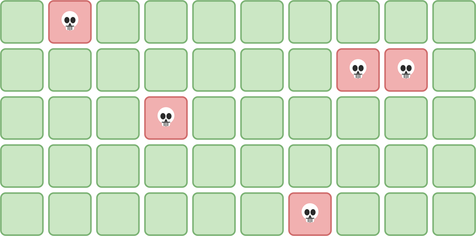
Even if the presence of Rust is slowly increasing in the Linux kernel code base, the project largely remains written in C, and while this is the de facto language to write low level code, it unfortunately also comes with a significant ability of making mistakes, with the corresponding failures then coming in a wide variety of shapes: undefined behaviors, buffer overflows, segmentation faults… The kernel is not immune to such issues, and so kernel developers need some dedicated tooling to catch those issues early. As many problems have their roots in memory management, one tool that can legitimately sit in any kernel hacker toolbox is the Kernel Address Sanitizer, or KASAN for short. This blog does not aim to teach readers how to use KASAN: the kernel documentation is pretty explicit on this matter. We are rather going to explore KASAN internals, mostly to understand its impact (both at build time and at runtime), but up to some extent, to appreciate the elegant engineering involved in its implementation!
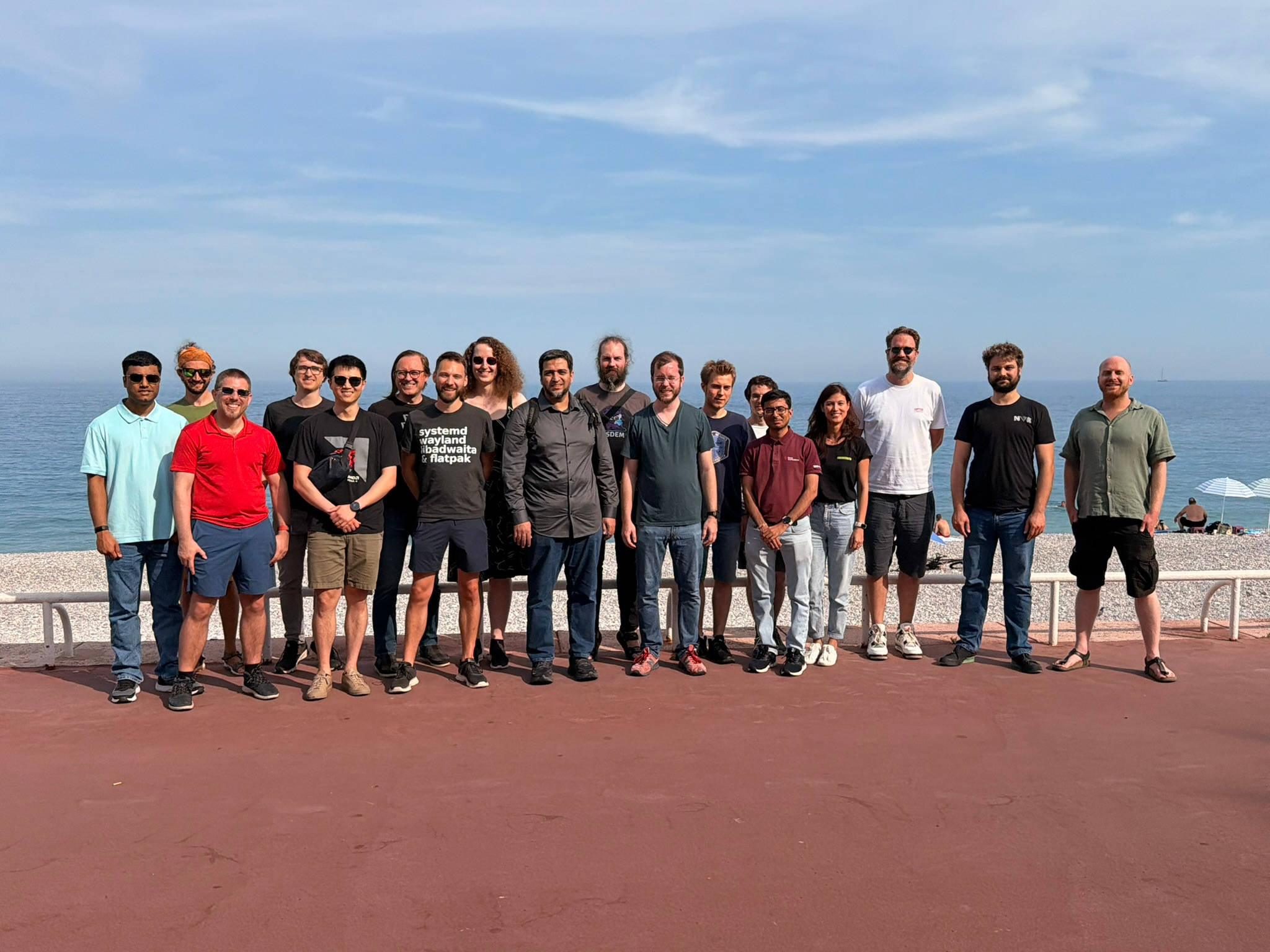
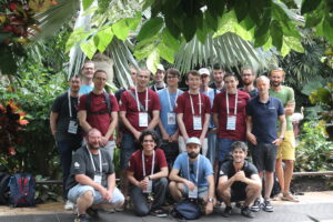
For the fifth time, the Bootlin team attended the Embedded Recipes conference to meet and share with the embedded community. This year, like last year, it was in the beautiful city of Nice. We were also proud to be a Chef Sponsor of the event.
As usual, here is a blog post with summaries of a few talks. You can find the full schedule here, and video recordings are now available for day 1 and day 2.
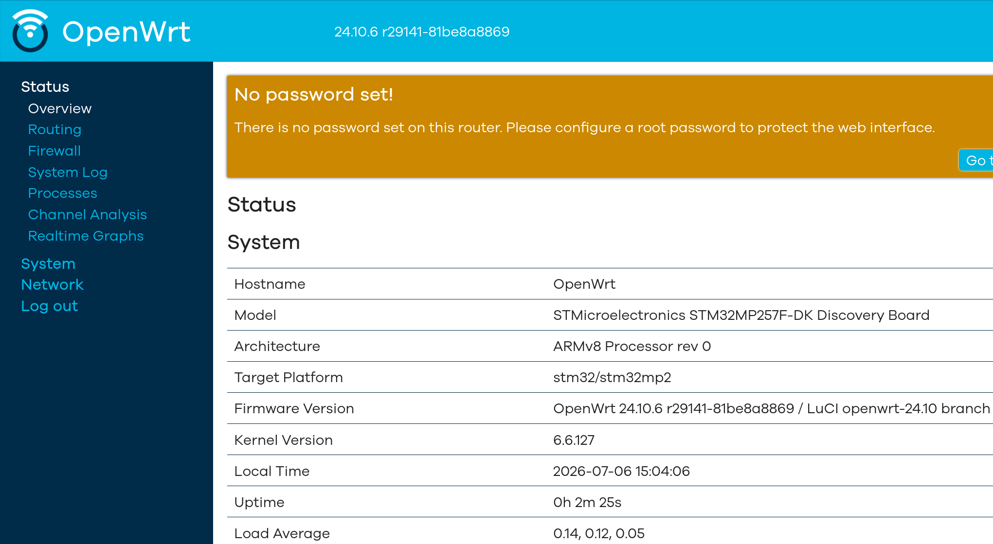
We’re excited to share some significant updates to our yocto-kiss project, our example of the simplest but realistic Yocto/OpenEmbedded setup. These changes improve the project’s organization, make it more scalable, and add support for a new ZynqMP-based platform.
As part of a project I am currently working on at Bootlin, I had the opportunity to attend the Linux Storage, Filesystem, Memory Management and BPF conference (enough of a mouthful to shorten to LSFMMBPF !) earlier in May. The conference took place this year in Zagreb from May 4th to May 6th, and was a fantastic opportunity to meet people working in deep technical topics in the Linux kernel.
Linux 7.1 was released earlier this week. As usual, the best source of information about the content of this new version will be LWN, see merge windows posts, part 1 and part 2 . This release is a bit outstanding, as it is one of the largest in kernel history, considering commits count. It also highlights a trend that has been visible since 7.0: the number of first-time contributors is increasing a lot. You can find some comments about this tendency in the 7.1 coverage from LWN.
This time again, Bootlin has been very active, as no less than 116 commits were contributed by Bootlin engineers, making the company rank at 21th according to the Linux Kernel Patch Statistics.
More specifically, this project is a BR2_EXTERNAL repository for Buildroot, with a number of defconfigs that allow to quickly build embedded Linux systems for the STM32MPU Discovery Kit platforms and Evaluation board. It’s a great way to get started with Buildroot on those platforms.
From May 29 to May 31, 2026, the Linux Display Next Hackfest convened in the vibrant city of Nice, France, just after Embedded Recipes 2026. This time the event was hosted by Collabora. This annual gathering has established itself as a cornerstone event for the Linux Graphics community, bringing together a dynamic mix of kernel developers, compositor maintainers and hardware vendor to push the boundaries of Linux Graphics innovation.
For the third consecutive year, Bootlin was proud to participate, this time with a team of three: Köry Maincent, Luca Ceresoli, and Louis Chauvet. Our involvement in this event is more than just attendance, that’s a way to build a bridge between our customers needs and the Linux community.
This year’s Hackfest was particularly rich in discussions, covering a broad spectrum of topics such as MST bandwidth allocation, Native DisplayID, tiled monitors, color operations, Variable Refresh Rate, and High Dynamic Range. We presented four critical areas for which we aim at bringing improved upstream support, to meet the needs of our customers:
Link training and firmware update issues on DisplayPort
Back in December 2025, we announced the release of sbom-cve-check, a lightweight CVE analysis tool for your Software Bill of Materials (SBOM). Since the announcement, we have announced a number of updates and new releases, but work has continued, and we have several new updates to share about sbom-cve-check.
 For the fifth time, the Bootlin team attended the
 As part of a project I am currently working on at Bootlin, I had the opportunity to attend the
  earlier this week
 The
The