Bootlin will be at the Netdev 0x17 conference, subtitled THE Technical Conference on Linux Networking. It is indeed one of the major event for developers working on the networking side of the Linux kernel to gather and discuss current and future topics. This year, the conference will take place from Oct 30 to Nov 3 in Vancouver, Canada.
Bootlin is involved in a number of Linux kernel networking developments: development and/or improvement of Linux kernel drivers for Ethernet MACs, Ethernet PHYs, WiFi chips, support for SFP, for Ethernet switches, for PTP offloading, for MACsec offloading, improvements to the 802.15.4 stack, and more. As such, it is very relevant for us to meet the Linux kernel networking community, present our work, and understand where things are heading to in the networking stack.
This talk will describe current use-cases where one MAC is connected to multiple PHYs (chained, or in parallel) and multiple front-facing ports, either through multiple PHYs or through a single multi-port PHY. There exist support for some of these scenarios already, but it is limited by the fact that the PHY device is hidden behind a net_device from userspace’s point of view. We therefore can’t configure an individual PHY when multiple PHYs are present on a link (through SFP transceivers for example), and selecting which front-facing port to use is also limited. This talk will describe ongoing work to support these complex topologies, the challenges faced and expected improvements.
We look forward to attending this event in a few weeks time!
Systemd is a popular init system, used to bootstrap user space and manage user processes. It now replaces several Linux utilities with its own components like log management, networking, time management, etc. There is even a bootloader component now. Systemd is obviously ubiquitous nowadays for desktop/server Linux distributions, and is also commonly used on embedded devices to benefit from features such as parallel startup of services, monitoring of services, and more.
In a recent project that uses Buildroot as its build system, we have used systemd with the storage consisting of a read-only root filesystem (SquashFS) and an overlay file system (OverlayFS) mounted on /etc. While doing this, we faced two issues with the use of OverlayFS on /etc:
/etc/machine-id file management. This file is created during the first boot by systemd, and if the root filesystem is read-only, it will bind mount it to /run and wait to have read-write access to create it (see more details). In that case, the machine-id file is re-generated at each boot (because /run is a tmpfs, which means that the machine identification changes at each boot, which is not necessarily desirable. On the other hand, we don’t want to machine-id file to be part of the SquashFS filesystem because the SquashFS filesystem is identical on all devices, while the /etc/machine-id file is unique per device. So ideally, we would like this machine-id file to be stored in our OverlayFS, generated during the first boot. The issue is that reading the machine-id file is done very early by systemd, before we get the chance to mount the OverlayFS.
We wanted to be able to add or modify systemd services using the OverlayFS. Systemd parses the service files at early init and executes them according to their order and dependencies. The service mounting the filesystems from /etc/fstab and any other services is started after such parsing, which is too late. We could think of running daemon-reload from a custom service once mounting was complete, but this is not really a stable solution, as
Lennart Poettering commanted on in a short e-mail thread about this issue.
The solution suggested by Lennart, and elsewhere on the wider Internet is to mount the OverlayFS from an initramfs, which allows to have it setup before systemd even starts. As we use Buildroot and using an initramfs adds complexity by requiring a separate configuration to manage multiple images. This was overkill in our case, just for setting up the overlay. The solution we eventually chose was to create an init_overlay.sh script which is started as init before systemd, by adding init=/sbin/init_overlay.sh to the kernel command line:
#!/bin/sh
mount -t proc -o nosuid,nodev,noexec none /proc
mount -t sysfs -o nosuid,nodev,noexec none /sys
mount /dev/mmcblk0p2 /mnt/data
mount -t overlay overlay -o lowerdir=/etc,upperdir=/mnt/data/etc,workdir=/mnt/data/.etc-work /etc
exec /sbin/init
Hopefully, this will be useful to others. Of course, we’re also curious to hear if others faced the same issue, and discover how they solved this. Let us know in the comments.
A few months ago, Bootlin released Snagboot, an open-source and generic replacement to the vendor-specific, sometimes proprietary, tools used to recover and reflash embedded platforms. This has led us to design recovery processes over USB for several different SoC families.
Our goal for each recovery process was the following: be able to upload U-Boot in external RAM and run it without modifying any non-volatile memories. Implementing this for many different platforms was challenging, as each vendor used different protocols, bootloader binaries, and methods to boot from recovery mode. Moreover, it was critical that the recovery tool be as user-friendly as possible, not requiring any complex configuration or vendor-specific workflows. This blog post describes the strangest recovery process we had to support so far: the one provided over USB by the Texas Instruments AM335x SoC.
Initializing AM335x platforms
When booted, each SoC has a specific sequence of actions it performs to load and run a target operating system or bare-metal program. This sequence typically starts with a ROM code, stored in a non-volatile internal memory. The main job of a ROM code is to search for a first-stage bootloader in various external memories and load it to internal RAM. In the case of AM335x platforms, this initialization sequence is described in the TI reference manual.
AM335x initialization procedure
As we can see, there is nothing too outlandish here. The ROM code checks each device in its boot sequence and attempts to boot from it. What is particularly interesting to us here is the Boot from peripheral device part. Indeed, our ultimate goal is to send U-Boot to the SoC over a USB connection. So we will now dig a little further into this peripheral boot feature. The reference manual states that the AM335x ROM code is capable of booting from three types of peripheral interfaces: EMAC (Ethernet), USB and UART. Considering what we said earlier, what really interests us here is the USB boot feature. The USB boot procedure is described in more detail in the reference manual. And this is where things get a little strange.
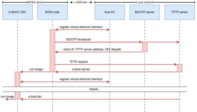
Most ROM codes we’ve encountered use fairly simple vendor protocols to communicate over USB. You’ll typically find some memory read/write operations, some run operations, and maybe a few vendor-specific commands. The AM335x ROM code however, uses network protocols to boot over USB! Specifically, the ROM code exposes an RNDIS class device which will be registered as an Ethernet interface by the host-side rndis_host driver. The ROM code will then broadcast BOOTP requests. A BOOTP server on the network should respond to this and supply the SoC with an IP address and the address of a TFTP server. Finally, the ROM code will download the first stage firmware from this TFTP server. To summarize, here is the expected USB boot procedure for AM335x SoCs:
AM335x boot sequence
This poses a number of issues. Remember, our goal is to boot the SoC using snagboot, a user-friendly and easily configurable CLI tool. Meaning we can’t expect the user to perform any complicated network configurations to be able to use the tool! So these are the main challenges associated with recovering AM335x SoCs:
We need a BOOTP and TFTP server to respond to the ROM code. These servers need IP addresses, which means our tool has to obtain IPs every time it runs.
BOOTP and TFTP servers use ports 67 and 69 which are privileged. However, we don’t want users to have to run snagboot as root.
The ROM code requires an IP address, which means that snagboot has to supply a valid IP address to it every time it runs the recovery.
If another BOOTP server is present on the user’s network during recovery, it could try to answer the ROM code, interfering with snagboot’s operation.
Designing a user-friendly recovery process
To circumvent these challenges, we made use of a number of nice Linux features. Firstly, we can see that the common theme in all these issues is interference with the user’s network. We have to work with local routers to get IP addresses, and we have to ensure that other BOOTP servers will not race us to respond to the board. To address this need, we’ve made use of network namespaces, which are a way of partitioning network resources on the system. When a process runs in a separate network namespace, it will not share network interfaces, routing rules, or firewall rules with the rest of the system.
This is very interesting to us, as it means that we can effectively create a sandbox environment where we can interact with the AM335x ROM code without touching the user’s local network! We can set whatever strange routing and firewall rules we want, and they will be automatically destroyed when we delete the namespace! The general sequence for our recovery process is:
Move the ROM Code’s virtual ethernet interface to a new “snagbootnet” namespace
Set up firewall rules to link ports 67 and 69 to unprivileged ports 9067 and 9069, which will spare us from running as root.
Set up routing rules to assign whatever IP’s we want to the ROM interface and the servers generated by snagboot.
Run snagrecover which will serve a U-Boot SPL image to the ROM Code
Repeat the same process to serve a U-Boot image to SPL (SPL will use essentially the same boot process as the ROM code)
# These iptable rules will allow snagboot to use unprivileged ports 9067 and 9069
# as proxies for privileged ports 67 and 69
ip netns exec $NETNS_NAME iptables -t nat -A PREROUTING \
   -p udp --dport 67 -j DNAT --to-destination :9067
ip netns exec $NETNS_NAME iptables -t nat -A PREROUTING \
   -p udp --dport 69 -j DNAT --to-destination :9069
ip netns exec $NETNS_NAME iptables -t nat -A POSTROUTING \
   -p udp --sport 9067 -j MASQUERADE --to-ports 67
ip netns exec $NETNS_NAME iptables -t nat -A POSTROUTING \
   -p udp --sport 9069 -j MASQUERADE --to-ports 69
The network namespace and network configurations can be done by a wrapper script, that will be executed by the user before running snagboot normally. However, there is another challenging issue with this method. When U-Boot SPL runs, it will expose a new RNDIS interface which will be registered by the host system and be brought up in the default network namespace. This means that we will not be able to access SPL’s virtual ethernet interface from inside our custom network namespace! Thus, we must use one final trick to automatically move SPL’s interface inside our namespace when it is brought up. The namespace setup script will run a polling subprocess in the background. This subprocess will regularly check /sys/class/net for new interfaces matching certain USB addresses, and will automatically move them to our namespace once detected.
poll_interface () {
  # check for network interfaces with device nodes matching our ROM code
  # and SPL RNDIS gadget addresses
  ROMNETFILE=$(grep -l "PRODUCT=$ROMUSB" $(grep -l "DEVTYPE=usb_interface" /sys/class/net/*/device/uevent))
  SPLNETFILE=$(grep -l "PRODUCT=$SPLUSB" $(grep -l "DEVTYPE=usb_interface" /sys/class/net/*/device/uevent))
  if [ -e "$ROMNETFILE" ]; then
    config_interface "$(echo $ROMNETFILE | cut -d '/' -f 5)"
  fi
  if [ -e "$SPLNETFILE" ]; then
    config_interface "$(echo $SPLNETFILE | cut -d '/' -f 5)"
  fi
}
You can check out the full setup script by running snagrecover --am335-setup if you are interested.
With this, we have a complete recovery process for AM335! From the user’s points of view, the only big difference with other SoC recoveries is an additional helper script that needs to be run before snagrecover. Designing the AM335x support for Snagboot was a very interesting technical problem, with a solution that illustrated the flexibility offered by Linux systems.
As we reported in a previous blog post, almost the entire Bootlin engineering team was at the Embedded Linux Conference Europe in Prague in June. In order to share with our readers more about what happened at this conference, we have asked all engineers at Bootlin to select one talk they found interesting and useful and share a short summary of it. We will share this feedback in a series of blog posts: first post, second post, third post, this one being the fourth and final post of the series.
Do the Time Warp – the Rocky Horror PTP Show: Verification of Network Time Synchronization in the Real World
Talk by Johannes Zink, chosen by Bootlin engineer Köry Maincent
As we are currently dealing with PTP at Bootlin and facing several weird behaviors, this talk resonated well with our current state of mind. Currently, most of our clock usage uses NTP but some specific usage may need PTP to have high-precision clock synchronization between devices.
In this talk, Johannes first describes briefly the principles of PTP and its implementation in the Linux kernel, where the PTP is either managed by the MAC (often), the PHY or by software, and Userspace, with the description of the Linuxptp project. Then he goes straight to the issues he faced. For non-PTP users, it might be a bit harsh to follow the tests and oscilloscope measurements described by Johannes. He describes several possible issues and clock behaviors you can face, which might help a new PTP user to not spend too much time on debugging some tricky PTP behavior. Also one of the important things he notices is to “Always check your assumptions!”, which he wants to spread as a religious mantra. Using his common pitfalls and best practices may be a good thing when putting a hand in the PTP mechanism.
And don’t forget “Always check your assumptions!”!
As a Yocto user, you may have already wondered, ‘Why aren’t there official tools for creating and managing BitBake-based projects in a reproducible manner?’ Perhaps you have already used tools like repo, Git submodules, kas, or even created your own scripts.
In this talk, Alexander Kanavin – one of the major contributors to the Yocto project – introduces the tools currently under development within OE-core/poky to address this situation.
WirePlumber 0.5 Propelling PipeWire for the Embedded
Talk by Ashok Sidipotu, chosen by Bootlin engineer Alexandre Belloni
Ashok started to present a quick introduction to what Pipewire is. A nice block diagram explains what it looks like in action. Then the discussion switches to the session manager and why it is important. WirePlumber is now the default session manager, replacing PipeWire media session. It manages the control path and dynamically creates PipeWire objects.
The main changes are:
config syntax is switching from Lua to SPA JSON, just like PipeWire. More info is available is this blog post
the event dispatcher has been created to handle PipeWire signals. This allows to prioritize signals and to avoid race conditions. This feature has a nice example and a fairly complete blog post
This talk is a nice overview of what is happening in the PipeWire ecosystem which is now quite mature. It is also great to see the improvements and that the embedded use case is not forgotten.
We are pleased to welcome two additional engineers to our team based in Toulouse, France: Romain Gantois and Louis Chauvet.
Romain Gantois graduated from ISEP and completed his final internship at Bootlin during which he developed and published Snagboot, the generic and open-source board recovery and reflashing tool, and worked on an upstream Linux kernel driver for a Qualcomm Ethernet switch (patches will be submitted soon!). Following this internship, Romain is joining our team as a full-time embedded Linux and Linux engineer.
Louis Chauvet graduated from INSA Toulouse. He completed his final internship abroad, during which he worked on developing in Rust, in particular the development of Linux kernel drivers in Rust. Louis is also joining us as a full-time embedded Linux and Linux kernel engineer.
Both Romain and Louis are experienced Linux users and developers, with a solid education in low-level and embedded systems development. They will help us address more embedded Linux projects from our customers on a wide variety of topics, and are already benefiting from our training courses and the interaction with our senior engineers to quickly gain even more knowledge and experience.
As we reported in a previous blog post, almost the entire Bootlin engineering team was at the Embedded Linux Conference Europe in Prague in June. In order to share with our readers more about what happened at this conference, we have asked all engineers at Bootlin to select one talk they found interesting and useful and share a short summary of it. We will share this feedback in a series of blog post: first post, second post, this one being the third of the series.
rtla timerlat: Debugging Real-time Linux Scheduling Latency
Talk by Daniel Bristot de Oliveira, chosen by Bootlin engineer Maxime Chevallier.
Talks related to real-time linux debugging are pretty common at ELCE, I gave one myself in 2017 and I’ve been attending most of them since then. Besides a headache, what I could get from attending all these talks is that this topic is complex, time consuming, and that there’s a lot of different methodologies one can use to find the cause of these elusive problems.
Users who aren’t very familiar with the inner workings of the Linux Kernel can ask for help on mailing-lists, and the reply usually asks for a trace. This is where things get complicated, the Linux kernel tracer is very powerful, but can drown users in a flood of trace events from which it is difficult to extract the relevant data.
Hopefully, Daniel’s talk is going to make this kind of talk less common, as the tool he wrote and presented, rtla, makes it easy to gather important information about the cause of undesired latencies. By using cleverly placed trace-points, in-kernel testing tools (timerlat and osnoise) and an automated trace analyzer, rtla can not only detect latencies as cyclictest would, it can also give you what caused the latency. If it’s a blocking problem, rtla tells you which process is blocking your task. If it’s an interference, rtla will tell you which task or interrupt caused the latency, and can even detect if the hardware itself is the culprit.
For developers, this tool is also a perfect way to gather user feedback and bug reports that are small, precise and easily reproducible.
I therefore strongly recommend checking out Daniel’s talk and his dedicated blog article.
Zbus – the Lightweight and Flexible Zephyr Message Bus
Talk by Robrigo Peixoto, chosen by Bootlin engineer Thomas Perrot
Zbus is a new message bus for Zephyr allowing threads to communicate to many others, easily. This bus allows to implement several bus topologies:
one-to-one
one-to-many
Many-to-many
In addition, it can be used on very constrained systems.
In this talk, Rodrigo explained in detail how Zbus works, through a few examples. A thread can read or publish in bus channels, and when a message is published into a channel:
The Listener’s callbacks are executed
A notification is put to the subscriber’s queues
Then the subscriber will be executed by priority order
The bus is managed by a dispatcher, named Virtual Distributed Event Dispatcher (VDED) that is robust to priority inversion.
We found Zbus to be a very interesting feature because before there was no easy way to implement one-to-many and many-to-many topologies, but also one-to-one communications without having to manage the problems of inverting priorities and to use FIFO, LIFO, pipe, etc.
Linux Power ! (from the Perspective of a PMIC Vendor)
Talk by Matti Vaittinen, chosen by Bootlin engineer Kamel Bouhara.
PMICs (Power Management Integrated Circuit) are a key component of low power embedded systems as they often handle complexity in controlling various power voltages required by SoCs. In his talk Matti Vaittinen started by depicting the various devices that can be embedded in a PMIC (Power Management Integrated Circuit): watchdog, RTC, GPIOs are examples of such extra functionalities. He reminded us the reason why such devices are best fitted in the Linux MFD subsystem to take advantage of existing code. However the main subsystem used to implement support for a PMIC is the regulator subsystem and the talk gives us a good understanding of how it works, the concept of provider/consumer, how to register multiple regulators for a PMIC and how to handle specific events. A focus is made on error detection and how over current errors are reported over three categories:
PROTECTION : hardware level errors reported when protection limit is reached
ERROR: Unrecoverable errors that don’t directly involve hardware shutdown.
WARNING: System is still recoverable but requires specific action to be taken
Some PMICs also provide IRQs to notify errors or events and the kernel provides a helper function to handle such notifications and map them to specific actions depending on their severity.
Overall, we found this talk interesting to understand bettert the features provided by PMICs, and how these features are supported by Linux.
Linux 6.5 was released yesterday, with as usual over 10,000 commits from a large number of contributors. We recommend reading LWN.net articles on the merge window (part 1, part 2), but also the CNX Software page that focuses on embedded-related improvements.
Bootlin contributed 76 commits to this kernel release, putting us as the #26 contributing company. This time around, our main contributions have been:
The large stack of patches from Luca Ceresoli on the NVidia Tegra camera interface driver finally landed: they add support for the Tegra20 parallel camera interface to the existing driver, which required a lot of changes to the driver that was so far only support Tegra210 CSI. This work allows one of our customers, who was stuck on an old vendor NVidia kernel to an upstream Linux kernel.
Hervé Codina contributed a driver for the Renesas X9250potentiometer, in the IIO subsystem. This will be followed in Linux 6.6 by a glue driver that allows to expose an IIO device as an auxiliary device in the ALSA subsystem, allowing this potentiometer to be used in audio applications
Alexis Lothoré contributed support for the Marvell MV88E6361 Ethernet switch into the existing mv88e6xxx DSA driver
Maxime Chevallier contributed a new regmap-based MDIO driver, which required some changes in the regmap code. This allows the Altera TSE driver to use the existing Lynx PCS driver, and drop the custom Altera TSE PCS driver. Finally, the stmmac Ethernet driver is modified to be able to use the Lynx PCS driver as well. Quite an adventure to finally get proper PCS support with stmmac
Miquèl Raynal contributed improvments in the 802.15.4 stack, especially related to scanning support.
Miquèl Raynal contributed fixes to the sja1000 CAN driver (to avoid overrun stalls on Renesas processors), to the SPI subsystem (to avoid false timeouts for long transfers), to the DMA engine driver for Xilinx XDMA IP, and a few more.
Miquèl Raynal also continued his effort of improving the Device Tree bindings for MTD NAND controllers
Luca Ceresoli added sound card support to the MSC SM2-MB-EP1 carrier board, which runs a i.MX8MP SoM, and he also fixed the timings for one of the panels supported by the simple-panel driver
Here are the details of all our changes that went into Linux 6.5:
The Embedded Recipes conference was started a few years ago, modeled after the popular Kernel Recipes conference. Both events follow an unusual but very interesting format: a single-track conference, with a carefully chosen set of talks/speakers, and a limited number of attendees. These “design choices” give those events a different atmosphere than larger events, whether they are corporate-driven or community-driven.
This year, the Embedded Recipes conference will take place in Paris on September 28-29, with two full days of talks, but also opportunities to connect which are facilitated by the smaller audience and single-track nature of the event. The schedule is now online.
Bootlin has decided to support this year’s edition by being one of the Chef sponsors, contributing financially to the sustainability of this conference. In addition, Bootlin engineer Romain Gantois will give a lightning talk about Snagboot, our recently released open-source and HW agnostic tool to recover and reflash embedded platforms.
If you’re interested in meeting with Bootlin folks, do not hesitate to reach out. Remember: we are still hiring, and looking for engineers with embedded Linux and/or Linux kernel experience to join our team. Meeting at this conference would be a great opportunity to start the conversation!
In the mean time, we can only recommend one thing: plan on attending the conference, and register now!
End of June, we announced the availability of a brand new training course, Embedded Linux Audio, which is targeted at engineers working with audio on embedded Linux systems, and that covers topics ranging from audio hardware, audio support in the Linux kernel (ASoC, DAI and codec drivers, Device Tree representation), audio support in user-space (alsa-lib, alsa-utils, PipeWire, GStreamer).
We are pleased to announce today that the training materials are now available for download. This again shows our commitment to sharing all our training materials for free, under an open-source license (Creative Commons BY-SA).
This training course has already been given earlier this year to a private customer, and we are releasing the materials before the very first public session, which will take place on September 11 to September 14, and which will be taught by Bootlin engineer and COO Alexandre Belloni. If you’re interested, registration is open, we have a few seats remaining.
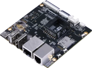
Earlier this year, the BeagleBoard.org foundation announced the availability of a new development board, the BeaglePlay, centered around the Texas Instruments AM625 ARM64 processor. Bootlin has for a long time supported the BeagleBone Black as one of the hardware platforms used in the practical labs of its training courses, and we are happy to announce today that we now have added support for the BeaglePlay to our most popular course, the Embedded Linux system development course.
This means that participants to our Embedded Linux system development course can now choose to perform the practical labs on the BeaglePlay, experiencing a new and modern hardware platform, based on an ARM64 processor. This applies not only to participants choosing to purchase our course, but also to everyone else in the world, as our training materials are all freely available and distributed under an open-source license. The materials are all available on our Embedded Linux system development training course page:
We would like to thank Clément Ramirez who has worked with us on this effort of porting this course to the BeaglePlay platform.
“Bootlin is a leading provider of high-quality, in-depth Linux education. What amazes me is how much they not only support open source with outstanding teaching, but how much they stand behind the principles of open source by sharing their teaching materials and contributing to the open source projects that drive them.” said Jason Kridner, founder of BeagleBoard.org. “BeagleBoard.org shares these principles and that is why I believe BeaglePlay is an excellent choice. BeaglePlay doesn’t just run open source software, the hardware itself is open source with detailed documentation on the board and associated Texas Instruments AM625 system-on-chip, with availability to enable hobbyists and professionals alike from prototype to production. I couldn’t be more excited.”
Bootlin’s Embedded Linux course, like all our training courses, is available in 3 different options:
Public on-line sessions, delivered by video-conference, with a per-participant registration, and sessions organized at dates scheduled by Bootlin. See this page for more details, dates and registration process
Private on-line sessions, also delivered by video-conference, organized privately for your team, at the date of your choice. See this page for more details
Private on-site sessions, where one of our experienced engineers and trainers travels to your location, to teach your team in person. See this page for more details
In both our private on-line sessions and private on-site sessions, our customers are free to chose, among our set of supported platforms, the HW platform they would like to use for the practical labs, and this now includes the BeaglePlay. In our public on-line sessions, the trainer demonstrates the practical labs on one particular platform, but participants are able to reproduce the labs on the platform of their choice among our supported platforms.
With this new development, we look forward to continue our mission of helping the broader engineering community get trained on embedded Linux technology and expand the number of users and contributors to open-source technologies and communities.
 Bootlin will be at the Netdev 0x17 conference, subtitled THE Technical Conference on Linux Networking. It is indeed one of the major event for developers working on the networking side of the Linux kernel to gather and discuss current and future topics. This year, the conference will take place from Oct 30 to Nov 3 in Vancouver, Canada.
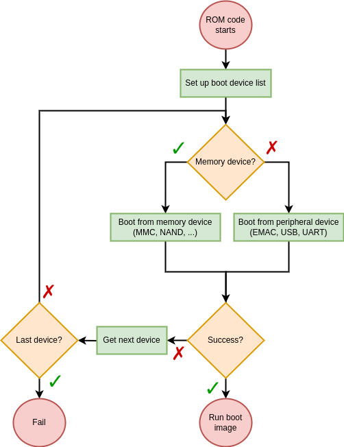
 We are pleased to welcome two additional engineers to our team based in Toulouse, France:
  The
The 
 Earlier this year, the