As described in previous articles (Introduction to PipeWire, Hands-on installation of PipeWire), the PipeWire daemon is responsible for running the graph execution. Nodes inside this graph can be implemented by any process that has access to the PipeWire socket that is used for IPC. PipeWire provides a shared object library that abstracts the communication with the main daemon and the communication with the modules that are required by the client.
In this blog post, our goal will be to implement an audio source node that plays audio coming from a file, in a loop. This will be an excuse to see a lot of code, showing what the library API looks like and how it should be used. To introduce some dynamism to a rather static setup, we’ll rely on an input from a Wii Nunchuck, connected using a custom Linux driver and relying on the input event userspace API.
A node, in the PipeWire sense, is a graph object that can consume and/or produce buffers. The main characteristic of a node is to have ports; those are graph objects described by a direction (input or output), an ID and some properties.
A basic PipeWire source node
To create a node, we will have to:
- Create an instance of one of the event loop implementations (
pw_data_loop,pw_thread_looporpw_main_loopfor the moment); - Create a
pw_contextusingpw_context_new; - Connect the context to the PipeWire daemon using
pw_context_connectwhich returns a proxy to the core object (whose ID is zero); - Create the node object (
spa_node), initialise its properties, register its methods (set_param, process, enum_params, etc.; seestruct spa_node_methodsfor the full list) and export it to the core so that the object becomes part of the graph (usingpw_core_export); - For each port, emit a
port_infoevent on the node object, that will be picked up by the node implementation which will create and export the global port object.
Steps 4 and 5 are rather complex and prone to errors and, as such, PipeWire provides two abstractions to facilitate node creation:
- A filter is the small abstraction over steps 4 and 5 from above. The filter constructor takes a proxy to the core object, a name and properties. Input or output ports can then be added using
pw_filter_add_port, which returns a pointer to user memory allocated for the port. It has a few events which can be listened upon; the only required one isprocesswhich is responsible for consuming data from input ports and producing data for output ports. The audio data format for both is raw floats. In theprocesscallback, the user pointer given as the return value ofpw_filter_add_portis used as an identifier for the port to retrieve the port’s data buffer. - A stream is also an abstraction over steps 4 and 5 from above, but more focused. The main issue it targets is format negotiation; it defines a list of supported formats and there is a format negotiation that happens before it being connected to another node. The adapter module is used to support input format conversion, channel-mixing, resampling and output format conversion.
What follows is therefore the full implementation of a PipeWire client that creates a source node using pw_stream. The code is heavely commented, so that it documents itself.
#include <errno.h>
#include <math.h>
#include <signal.h>
#include <stdio.h>
#include <sys/time.h>

#include <pipewire/pipewire.h>
#include <sndfile.h>
#include <spa/param/audio/format-utils.h>

/* A common pattern for PipeWire is to provide a user data void
   pointer that can be used to pass data around, so that we have a
   reference to our memory structures when in callbacks. The norm
   is therefore to store all the state required by the client in a
   struct declared in main, and passed to PipeWire as a pointer.
   struct data is just that. */
struct data {
    /* Keep some references to PipeWire objects. */
    struct pw_main_loop *loop;
    struct pw_core *core;
    struct pw_stream *stream;

    /* libsndfile stuff used to read samples from the input audio
       file. */
    SNDFILE *file;
    SF_INFO fileinfo;
};

static void on_process(void *userdata);
static void do_quit(void *userdata, int signal_number);
static const struct pw_stream_events stream_events;

int main(int argc, char **argv)
{
    struct data data = { 0, };

    /* A single argument: path to the audio file. */
    if (argc != 2) {
        fprintf(stderr,
            "expected an argument: the file to open\n");
        return 1;
    }

    /* We initialise libsndfile, the library we'll use to convert
       the audio file's content into interlaced float samples. */
    memset(&data.fileinfo, 0, sizeof(data.fileinfo));
    data.file = sf_open(argv[1], SFM_READ, &data.fileinfo);
    if (data.file == NULL) {
        fprintf(stderr, "file opening error: %s\n",
            sf_strerror(NULL));
        return 1;
    }

    /* We initialise libpipewire. This mainly reads some
       environment variables and initialises logging. */
    pw_init(NULL, NULL);

    /* Create the event loop. */
    data.loop = pw_main_loop_new(NULL);

    /* Create the context. This is the main interface we'll use to
       interact with PipeWire. It parses the appropriate
       configuration file, loads PipeWire modules declared in the
       config and registers event sources to the event loop. */
    struct pw_context *context = pw_context_new(
        pw_main_loop_get_loop(data.loop),
        pw_properties_new(
            /* Explicity ask for the realtime configuration. */
            PW_KEY_CONFIG_NAME, "client-rt.conf",
            NULL),
        0);
    if (context == NULL) {
        perror("pw_context_new() failed");
        return 1;
    }

    /* Connect the context, which returns us a proxy to the core
       object. */
    data.core = pw_context_connect(context, NULL, 0);
    if (data.core == NULL) {
        perror("pw_context_connect() failed");
        return 1;
    }

    /* Add signal listeners to cleanly close the event loop and
       process when requested. */
    pw_loop_add_signal(pw_main_loop_get_loop(data.loop), SIGINT,
        do_quit, &data);
    pw_loop_add_signal(pw_main_loop_get_loop(data.loop), SIGTERM,
        do_quit, &data);

    /* Initialise a string that will be used as a property to the
       stream. We request a specific sample rate, the one found in
       the opened file. Note that the sample rate will not be
       enforced: see PW_KEY_NODE_FORCE_RATE for that. */
    char rate_str[64];
    snprintf(rate_str, sizeof(rate_str), "1/%u",
        data.fileinfo.samplerate);

    /* Create the pw_stream. This does not add it to the graph. */
    data.stream = pw_stream_new(
        data.core, /* Core proxy. */
        argv[1],   /* Media name associated with the stream, which
                      is different to the node name. */
        pw_properties_new(
            /* Those describe the node type and are required to
               allow the session manager to auto-connect us to a
               sink node. */
            PW_KEY_MEDIA_TYPE, "Audio",
            PW_KEY_MEDIA_CATEGORY, "Playback",
            PW_KEY_MEDIA_ROLE, "Music",

            /* Our node name. */
            PW_KEY_NODE_NAME, "Audio source",

            PW_KEY_NODE_RATE, rate_str,
            NULL));

    /* Register event callbacks. stream_events is a struct with
       function pointers to the callbacks. The most important one
       is `process`, which is called to generate samples. We'll
       see its implementation later on. */
    struct spa_hook event_listener;
    pw_stream_add_listener(data.stream, &event_listener,
        &stream_events, &data);

    /* This is the stream's mechanism to define the list of
       supported formats. A format is specified by the samples
       format(32-bit floats, unsigned 8-bit integers, etc.), the
       sample rate, the channel number and their positions. Here,
       we define a single format that matches what we read from
       from the file for the sample rate and the channel number,
       and we use a float format for samples, regardless of what
       the file contains. */
    const struct spa_pod *params[1];
    uint8_t buffer[1024];
    struct spa_pod_builder b = SPA_POD_BUILDER_INIT(buffer,
        sizeof(buffer));
    params[0] = spa_format_audio_raw_build(&b,
            SPA_PARAM_EnumFormat,
            &SPA_AUDIO_INFO_RAW_INIT(
                .format = SPA_AUDIO_FORMAT_F32,
                .channels = data.fileinfo.channels,
                .rate = data.fileinfo.samplerate ));

    /* This starts by calling pw_context_connect if it wasn't
       called, then it creates the node object, exports it and
       creates its ports. This makes the node appear in the graph,
       and it can then be detected by the session manager that is
       responsible for establishing the links from this node's
       output ports to input ports elsewhere in the graph (if it
       can).

       The third parameter indicates a target node identifier.

       The fourth parameter is a list of flags:
        - we ask the session manager to auto-connect us to a sink;
        - we want to automatically memory-map the memfd buffers;
        - we want to run the process event callback in the realtime
          thread rather than in the main thread.
       */
    pw_stream_connect(data.stream,
              PW_DIRECTION_OUTPUT,
              PW_ID_ANY,
              PW_STREAM_FLAG_AUTOCONNECT |
              PW_STREAM_FLAG_MAP_BUFFERS |
              PW_STREAM_FLAG_RT_PROCESS,
              params, 1);

    /* We start the event loop. Underlying to this is an epoll call
       that listens on an eventfd. In this example, the process
       gets woken up regularly to evaluate the process event
       handler. */
    pw_main_loop_run(data.loop);

    /* pw_main_loop_run returns when the event loop has been asked
       to quit, using pw_main_loop_quit. */
    pw_stream_destroy(data.stream);
    spa_hook_remove(&event_listener);
    pw_context_destroy(context);
    pw_main_loop_destroy(data.loop);
    pw_deinit();
    sf_close(data.file);

    return 0;
}

/* do_quit gets called on SIGINT and SIGTERM, upon which we ask the
   event loop to quit. */
static void do_quit(void *userdata, int signal_number)
{
    struct data *data = userdata;
    pw_main_loop_quit(data->loop);
}

/* This is a structure containing function pointers to event
   handlers. It is a common pattern in PipeWire: when something
   allows event listeners, a function _add_listener is available
   that takes a structure of function pointers, one for each
   event. Those APIs are versioned using the first field which is
   an integer version number, associated with a constant declared
   in the header file.

   Not all event listeners need to be implemented; the only
   required one for a stream or filter is `process`. */
static const struct pw_stream_events stream_events = {
    PW_VERSION_STREAM_EVENTS,
    .process = on_process,
};

/* on_process is responsible for generating the audio samples when
   the stream should be outputting audio. It might not get called,
   if the ports of the stream are not connected using links to
   input ports.

   The general process is the following:
     - pw_stream_dequeue_buffer() to retrieve a buffer from the
       buffer queue;
     - fill the buffer with data and set its properties
       (offset, stride and size);
     - pw_stream_queue_buffer() to hand the buffer back to
       PipeWire.

   We'll use the following calling convention: a frame is composed
   of multiple samples, one per channel. */
static void on_process(void *userdata)
{
    /* Retrieve our global data structure. */
    struct data *data = userdata;

    /* Dequeue the buffer which we will fill up with data. */
    struct pw_buffer *b;
    if ((b = pw_stream_dequeue_buffer(data->stream)) == NULL) {
        pw_log_warn("out of buffers: %m");
        return;
    }

    /* Retrieve buf, a pointer to the actual memory address at
       which we'll put our samples. */
    float *buf = b->buffer->datas[0].data;
    if (buf == NULL)
        return;

    /* stride is the size of one frame. */
    uint32_t stride = sizeof(float) * data->fileinfo.channels;
    /* n_frames is the number of frames we will output. We decide
       to output the maximum we can fit in the buffer we were
       given, or the requested amount if one was given. */
    uint32_t n_frames = b->buffer->datas[0].maxsize / stride;
    if (b->requested)
        n_frames = SPA_MIN(n_frames, b->requested);

    /* We can now fill the buffer! We keep reading from libsndfile
       until the buffer is full. */
    sf_count_t current = 0;
    while (current < n_frames) {
        sf_count_t ret = sf_readf_float(data->file,
            &buf[current*data->fileinfo.channels],
            n_frames-current);
        if (ret < 0) {
            fprintf(stderr, "file reading error: %s\n",
                sf_strerror(data->file));
            goto error_after_dequeue;
        }

        current += ret;

        /* If libsndfile did not manage to fill the buffer we asked
           it to fill, we assume we reached the end of the file
           (as described by libsndfile's documentation) and we
           seek back to the start. */
        if (current != n_frames &&
                sf_seek(data->file, 0, SEEK_SET) < 0) {
            fprintf(stderr, "file seek error: %s\n",
                sf_strerror(data->file));
            goto error_after_dequeue;
        }
    }

    /* We describe the buffer we just filled before handing it back
       to PipeWire.  */
    b->buffer->datas[0].chunk->offset = 0;
    b->buffer->datas[0].chunk->stride = stride;
    b->buffer->datas[0].chunk->size = n_frames * stride;
    pw_stream_queue_buffer(data->stream, b);

    return;

error_after_dequeue:
    /* If an error occured after dequeuing a buffer, we end the
       event loop. The current buffer will be sent to the next
       node so we need to make it empty to avoid sending corrupted
       data. */

    pw_main_loop_quit(data->loop);
    b->buffer->datas[0].chunk->offset = 0;
    b->buffer->datas[0].chunk->stride = 0;
    b->buffer->datas[0].chunk->size = 0;
    pw_stream_queue_buffer(data->stream, b);
}
We will now want to compile this and integrate it into our root filesystem image. The easiest way for that is to create a custom Buildroot package. If in doubt during this step, the Buildroot manual can be a good ally as it is well written and does not gloss over any detail.
Before creating a Buildroot package, we’ll finish packaging our program by putting it into $WORK_DIR/pw-nodes/basic-source.c and creating a minimal Makefile that can compile it (used later on by the Buildroot package):
CFLAGS += $(shell pkg-config --cflags libpipewire-0.3 sndfile)
LDLIBS += -lm $(shell pkg-config --libs libpipewire-0.3 sndfile)

basic-source: basic-source.o
    $(CC) -o $@ $^ $(LDLIBS)

%.o: %.c
    $(CC) -c -o $@ $< $(CFLAGS)

.PHONY: clean
clean:
    find . -name "*.o" | xargs -r $(RM)
    $(RM) basic-source
The steps to create our package is as follows:
- Create the
buildroot/package/pw-nodes/pw-nodes.mkmakefile, that declares the package’s vital informations, its build step and the steps to copy it into the staging and target environments. - Create the
buildroot/package/pw-nodes/Config.inKconfig file, that registers a new configuration option. - Edit the
buildroot/package/Config.into declare the new kconfig file.Config.infrom packages do not get discovered automatically.
Here is what the makefile could look like:
################################################################################
#
# pw-nodes
#
################################################################################

PW_NODES_VERSION = 0
# TODO: substitute $WORK_DIR manually
PW_NODES_SITE = $WORK_DIR/pw-nodes
PW_NODES_SITE_METHOD = local
PW_NODES_DEPENDENCIES = host-pkgconf pipewire libsndfile

define PW_NODES_BUILD_CMDS
    $(TARGET_MAKE_ENV) $(TARGET_CONFIGURE_OPTS) \
        $(MAKE) -C $(@D) basic-source
endef

define PW_NODES_INSTALL_TARGET_CMDS
    $(INSTALL) -m 0755 -D $(@D)/basic-source $(TARGET_DIR)/usr/bin/basic-source
endef

$(eval $(generic-package))
And the kconfig file:
config BR2_PACKAGE_PW_NODES
    bool "pw-nodes"
    help
      A custom package that includes our own PipeWire nodes.
Tip: check your package’s files using the check-package tool that can be found in the utils directory of every Buildroot install.
We can now update our project’s configuration to add the new package using make menuconfig, and recompile our project so that the new program gets added to the root filesystem image. We can extract our root filesystem image and reboot our board to test our program:
cd $WORK_DIR/buildroot
make
cd ..
sudo rm -rf rootfs
mkdir rootfs
tar xf buildroot/output/images/rootfs.tar -C rootfs
Tip: PipeWire running on both desktop and embedded, programs such as the previous one can easily be run on the host if it is running PipeWire as its audio processing engine. This is practical to experiment and iterate with PipeWire’s specifics quickly.
Dynamic, I2C-controlled PipeWire node
Now that we have a working source program that can output audio to the PipeWire graph, let’s make it dynamic! We’ll rely upon a Wii Nunchuck for this, connected over I2C. We’ll expose this peripheral using a custom driver that will make our Nunchuck available over the input subsystem userspace API. A few steps are required in order to make those changes:
- The driver has to be added to the kernel, and enabled.
- The device tree has to be updated in order to register the new peripheral, that will communicate over an I2C bus.
- Our program has to be updated to rely upon evdev, the generic input event interface, for receiving input events and acting appropriately.
As the first two bullet points are outside the scope of our experiments, here is a patch that provides those changes.
We connect our Nunchuk to the exposed SCL0 and SDA0 pins connectors. To find its address, the easiest way is to rely on the i2cdetect tool, that scans an I2C bus, returning a table of detected devices. Busybox provides an implementation:
# i2cdetect -qy 0
     0  1  2  3  4  5  6  7  8  9  a  b  c  d  e  f
00:          -- -- -- -- -- -- -- -- -- -- -- -- --
10: -- -- -- -- -- -- -- -- -- -- -- -- -- -- -- --
20: -- -- -- -- -- -- -- -- -- -- -- -- -- -- -- --
30: -- -- -- -- -- -- -- -- -- -- -- -- -- -- -- --
40: -- -- -- -- -- -- -- -- -- -- -- -- -- -- -- --
50: -- -- 52 -- -- -- -- -- -- -- -- -- -- -- -- --
60: -- -- -- -- -- -- -- -- -- -- -- -- -- -- -- --
70: -- -- -- -- -- -- -- --
Our modification to the device tree is therefore a new node in i2c0, of type joystick at address 0x52, with compatible = "nintendo,nunchuk".
Once the changes are applied and our system booted with the new device tree and kernel, the i2cdetect output changes, which confirms that our driver is handling the 0x52 address on i2c bus 0:
# i2cdetect -qy 0
     0  1  2  3  4  5  6  7  8  9  a  b  c  d  e  f
00:          -- -- -- -- -- -- -- -- -- -- -- -- --
10: -- -- -- -- -- -- -- -- -- -- -- -- -- -- -- --
20: -- -- -- -- -- -- -- -- -- -- -- -- -- -- -- --
30: -- -- -- -- -- -- -- -- -- -- -- -- -- -- -- --
40: -- -- -- -- -- -- -- -- -- -- -- -- -- -- -- --
50: -- -- UU -- -- -- -- -- -- -- -- -- -- -- -- --
60: -- -- -- -- -- -- -- -- -- -- -- -- -- -- -- --
70: -- -- -- -- -- -- -- --
i2cdetect works by opening /dev/i2c-0 (for bus 0), then doing a ioctl(fd, I2C_SLAVE, address) call for each possible address. errno == EBUSY means that the address is reserved by a kernel driver and i2cdetect prints UU in this case. Otherwise, it tries to read or write based on the mode i2cdetect was invoked with (-r or -q). In write mode, it writes an empty SMBus command; a successful operation means there is a device on the address.
Now that we know that our driver handles the i2c address, we can check that the input events are accessible through the generic input subsystem’s userspace interface: evdev. Each input is represented by a /dev/input/eventN character special file (that is a streaming file). evtest is a tool packaged by Buildroot under the BR2_PACKAGE_EVTEST symbol to read in a user-friendly manner events from an input:
# evtest
No device specified, trying to scan all of /dev/input/event*
Available devices:
/dev/input/event0:  Wii Nunchuk
/dev/input/event1:  gpio_keys
Select the device event number [0-1]: 0
Input driver version is 1.0.1
Input device ID: bus 0x18 vendor 0x0 product 0x0 version 0x0
Input device name: "Wii Nunchuk"
Supported events:
  Event type 0 (EV_SYN)
  Event type 1 (EV_KEY)
    Event code 304 (BTN_SOUTH)
    Event code 305 (BTN_EAST)
    Event code 306 (BTN_C)
    Event code 307 (BTN_NORTH)
    Event code 308 (BTN_WEST)
    Event code 309 (BTN_Z)
    Event code 310 (BTN_TL)
    Event code 311 (BTN_TR)
    Event code 312 (BTN_TL2)
    Event code 313 (BTN_TR2)
    Event code 314 (BTN_SELECT)
    Event code 315 (BTN_START)
    Event code 316 (BTN_MODE)
  Event type 3 (EV_ABS)
    Event code 0 (ABS_X)
      Value    126
      Min       30
      Max      220
      Fuzz       4
      Flat       8
    Event code 1 (ABS_Y)
      Value    132
      Min       40
      Max      200
      Fuzz       4
      Flat       8
Properties:
Testing ... (interrupt to exit)
Event: time 60.719169, type 3 (EV_ABS), code 0 (ABS_X), value 1
Event: time 60.719169, -------------- SYN_REPORT ------------
Event: time 60.919177, type 3 (EV_ABS), code 0 (ABS_X), value 126
Event: time 60.919177, -------------- SYN_REPORT ------------
Event: time 62.619168, type 3 (EV_ABS), code 0 (ABS_X), value 167
Event: time 62.619168, -------------- SYN_REPORT ------------
Event: time 62.719190, type 3 (EV_ABS), code 0 (ABS_X), value 254
Event: time 62.719190, -------------- SYN_REPORT ------------
Event: time 63.019155, type 3 (EV_ABS), code 0 (ABS_X), value 126
Event: time 63.019155, -------------- SYN_REPORT ------------
Event: time 64.319164, type 3 (EV_ABS), code 1 (ABS_Y), value 255
Event: time 64.319164, -------------- SYN_REPORT ------------
Event: time 64.619156, type 3 (EV_ABS), code 1 (ABS_Y), value 132
Event: time 64.619156, -------------- SYN_REPORT ------------
Event: time 65.318825, type 3 (EV_ABS), code 1 (ABS_Y), value 0
Event: time 65.318825, -------------- SYN_REPORT ------------
Event: time 65.618830, type 3 (EV_ABS), code 1 (ABS_Y), value 99
Event: time 65.618830, -------------- SYN_REPORT ------------
Event: time 65.719171, type 3 (EV_ABS), code 1 (ABS_Y), value 132
Event: time 65.719171, -------------- SYN_REPORT ------------
Event: time 67.419274, type 1 (EV_KEY), code 309 (BTN_Z), value 1
Event: time 67.419274, -------------- SYN_REPORT ------------
Event: time 67.619177, type 1 (EV_KEY), code 309 (BTN_Z), value 0
Event: time 67.619177, -------------- SYN_REPORT ------------
Event: time 68.319155, type 1 (EV_KEY), code 306 (BTN_C), value 1
Event: time 68.319155, -------------- SYN_REPORT ------------
Event: time 68.519157, type 1 (EV_KEY), code 306 (BTN_C), value 0
Event: time 68.519157, -------------- SYN_REPORT ------------
evtest starts by listing to us the list of detected inputs, with names declared by drivers. Once one is selected, it tells us informations about the input, including the list of supported event types and codes. Events are defined using the following structure in the evdev interface:
struct input_event {
    // Time of the event.
    struct timeval time;

    // Type of the event. EV_KEY means a change of button state.
    // EV_ABS means a change to an absolute axis value, which has
    // a range. EV_SYN are metadata markers that separate events
    // (notify dropped events, separate events in time or space).
    // There are others that won't concern us.
    unsigned short type;

    // The event identifier: BTN_{C,Z} for the two buttons on the
    // Nunchuk, ABS_{X,Y} for the two axis of our joystick.
    unsigned short code;

    // The value associated with the event: boolean for buttons,
    // between 0 and 255 inclusive for our two axis.
    unsigned int value;
};
We now have everything we require to edit our previous source node to add some dynamism to it. We’ll add a pause on the press of a button, as well as volume control. At init, we now have to:
- Find the correct file in
/dev/inputthat represents our Nunchuk device. For that, we’ll scan their names and use the one that has the “Nunchuk” keyword, as given by the kernel driver. - Add a file descriptor pointing to this file to the event-loop. This means that once the event-loop is started, the callback we will register will be called when events are available.
When our callback gets called, we need to know why we got woken-up (might be an error, a hang-up or available data). We can then read the structures and act as we like.
dynamic-source.c will be similar to basic-source.c, with the following additions:
#define DEV_INPUT_DIR "/dev/input"
#define FILE_PREFIX "event"
#define NUNCHUK_NAME_KEYWORD "Nunchuk"

/* Add our file-descriptor and callback to the event-loop. A
   negative return value means an error occured. */
int nunchuk_register(struct data *data)
{
    int fd = nunchuk_open_fd();
    if (fd < 0) {
        return -1;
    }

    int ret = fcntl(fd, F_SETFL, O_NONBLOCK);
    if (ret < 0) {
        perror("fcntl() failed");
        return -1;
    }

    /* We register our file descriptor to the event-loop. The third
       argument is a mask on the fd's events we want to be woken
       up to: in our case, we care when it is readable or when an
       error or hang-up occured. The fourth argument means that
       the event-loop will close automatically the fd when done.
       We then pass on the callback and a user pointer, which
       we'll want to retrieve in the callback. */
    pw_loop_add_io(pw_main_loop_get_loop(data->loop), fd,
        SPA_IO_IN | SPA_IO_ERR | SPA_IO_HUP, true,
        nunchuk_on_events, data);
}


/* Retrieve a file descriptor to the Nunchuk character device.

   This works by going over every device found in the input
   subsystem, exposed in /dev/input, and looking at their names.
   We keep the one that matches a specific keyword open and return
   its file descriptor. */
static int nunchuk_open_fd(void)
{
    DIR *d = opendir(DEV_INPUT_DIR);
    if (d == NULL) {
        perror("opendir() failed");
        return -1;
    }

    struct dirent *dir;
    while ((dir = readdir(d)) != NULL) {
        /* Filter out non block devices and files that don't have
           the right prefix. */
        if (dir->d_type != DT_CHR ||
                strncmp(FILE_PREFIX, dir->d_name,
                    strlen(FILE_PREFIX)) != 0)
            continue;

        char filepath[512];
        snprintf(filepath, sizeof(filepath), "%s/%s",
            DEV_INPUT_DIR, dir->d_name);
        int fd = open(filepath, O_RDONLY);
        if (fd < 0) {
            perror("open() failed");
            continue;
        }

        char name[256] = {0,};
        ioctl(fd, EVIOCGNAME(sizeof(name)), name);

        /* Search for the keyword in the input's name. */
        if (strstr(name, NUNCHUK_NAME_KEYWORD) != NULL) {
            closedir(d);
            return fd;
        }

        close(fd);
    }

    closedir(d);
    fprintf(stderr, "no Nunchuk input device found in %s\n",
        DEV_INPUT_DIR);
    return -1;
}

/* This function will be called by the event-loop when data is
   readable in the Nunchuk file descriptor, that is, when events
   are awaiting. We therefore read from the file descriptor and
   call the event handler for each event.

   We do a single read; if it fills up and there are still awaiting
   events, the event-loop will not go to sleep and we'll be called
   again. We could even read one event at a time if we were lazy.

   The mask tells us why we got woken up. We registered for input,
   errors and hang-ups. */
static void nunchuk_on_events(void *userdata, int fd,
    uint32_t mask)
{
    struct data *data = userdata;

    if (mask & (SPA_IO_ERR | SPA_IO_HUP)) {
        fprintf(stderr, "error or hang-up on the Nunchuk fd\n");
        pw_main_loop_quit(data->loop);
        return;
    }

    /* mask == SPA_IO_IN, that is we can read on the input
       character device. */

    struct input_event events[16];
    ssize_t ret = read(fd, events, sizeof(events));

    if (ret <= 0) {
        if (ret == EOF)
            fprintf(stderr,
                "read() on the Nunchuk input returned EOF\n");
        else
            perror("read() on the Nunchuk input failed");

        pw_main_loop_quit(data->loop);
        return;
    }

    for (size_t i = 0; i < ret / sizeof(struct input_event); i++)
        nunchuk_on_event(data, events[i]);
}

/* Called once for each Nunchuk event. */
static void nunchuk_on_event(struct data *data,
    struct input_event e)
{
    if (e.type == EV_KEY && e.code == BTN_Z) {
        /* This pauses the stream while the button is pressed.
           PulseAudio would call this corking, as in
           pa_stream_cork(). */
        pw_stream_set_active(data->stream, e.value == 0);
    } else if (e.type == EV_ABS && e.code == ABS_Y) {
        /* 0 <= e.value <= 255, which means data->volume will take
           a value between 0 and 1 inclusive. */
        data->volume = (float)e.value / 255;
    }
}

/* The return value is x, limited to the [a, b] interval. */
static float clampf(float x, float a, float b)
{
    if (x <= a) return a;
    if (x >= b) return b;
    else return x;
}
In addition to those function declarations, we:
- add a
float volumefield tostruct data; - call
nunchuk_register(&data)frommain; - set
data.volume = 0.5ffrommain, to avoid having a default value of zero for the volume; - Add the following block at the end of
on_process, to apply the volume change:// Clamping at the very end to avoid any bug that could hurt ears. float volume = clampf(data->volume, 0.0f, 1.0f); if (volume != 1.0f) { for (size_t i = 0; i < n_frames * data->fileinfo.channels; i++) buf[i] *= volume; }
Those changes enable us to control our stream using our i2c device. One thing might be surprising when running the experiment for the first time: the volume changes do not feel responsive to inputs. The reason is that we apply our volume filtering when we generate the samples buffer. Volume changes will therefore apply to blocks of samples, with a latency dependent on the graph’s execution frequency. If no follower node imposes a latency, the driver node’s one is used. In the current setup, the latency is set to 1024/48000, that is around 21ms.
The number of samples that is handled during one cycle is called the quantum. The stream abstracts this and allows one to provide more or less samples, providing buffering. It is called requested under the buffer structure.
To request for another latency, we can set the node.latency property on our stream node, when we create it. It works in the same way as node.rate:
#define QUANTUM 256
char rate_str[16], latency_str[16];

snprintf(rate_str, sizeof(rate_str), "1/%u", samplerate);
snprintf(latency_str, sizeof(latency_str), "%u/%u", QUANTUM, samplerate);

struct pw_stream *stream = pw_stream_new(core, media_name, pw_properties_new(
        /* ... */
        PW_KEY_NODE_RATE, rate_str,
        PW_KEY_NODE_LATENCY, latency_str,
        /* ... */
        NULL));
As can be seen, latency is expressed as a fraction. The denominator is often, but not enforced to be, the sample rate. The quantum is the buffer size in samples (per audio channel) that a node handles; it is therefore the numerator of the latency fraction when its denominator is the sample rate.
The quantum value is provided to us through the requested buffer field. The stream abstracts it and allows us to provide more samples, providing buffering, which is why the buffers are bigger than the quantum.
Note: a stream that wants to set its own volume should rather use pw_stream_set_control(stream, SPA_PROP_volume, 1, volume_as_float, 0). We only did it manually to get a feel for what the quantum is. This lets the stream’s audioconvert do the volume mixing (possibly using SIMD) and it triggers a flush, meaning the change is instantaneous.
Graph execution timings
PipeWire provides a module that is being loaded by the default configuration, that allows one to access profiling information about the nodes’ execution timing information.
The first important thing is that a node can be of two types: it can be a driver or a follower node. For each subgraph, there is a single driver node that is responsible, in addition to processing samples, of providing the timing: when should a graph execution cycle be started. Other nodes are followers; they get executed at every cycle.
Note: most follower nodes support not being connected to a driver node. They stay in a suspended state, with their process callback not being called. However, some nodes (in particular JACK nodes) do not support this, which is one of the reason for the graph to always contains a “Dummy-Driver” node. Another pretty-specific node is “Freewheel-Driver”, which is used to record samples as fast as possible: it is a driver node that starts the next cycle as soon as the previous one ended.
Every node, whether they are driver or follower, have the following three timing information available through the profiling module, for each execution cycle:
- Signal: the time at which a node was asked to run. The driver node’s signal time is the start of the new graph execution cycle.
- Awake: the time at which the node’s sample processing started. For a driver node, that is when the timeout occured, meaning that the underlying device expects to read (or write) samples if it is a sink (or source). A driver can awake itself before the execution is finished: it leads to an underrun.
- Finish: the time at which the node’s sample processing is done. For a driver node, it means the next execution cycle will run (equal to the next cycle’s signal).
The driver node is not always the one that is signaling follower nodes when they should process samples. If we have a graph with a source, a filter and an ALSA sink, the ALSA sink will act as the driver and trigger the cycle starts, which will signal the source node. Once the source node is finished, it will signal the filter node. On the other hand, if there are no inter-dependencies, nodes will be signaled at the same time and will execute concurrently.
Tools rundown
Now that we have our own node running, let’s go through the tools PipeWire provides to get a sense of the graph state.
PIPEWIRE_DEBUG variable
This isn’t a tool as such, but rather an environment variable. It is however really useful as it tells the PipeWire library to dump logs to stderr. By default, no logging is enabled. It can be raised to print warnings and errors using a value of 2. A value of 5 prints all possible messages, up to trace messages (some can still be disabled because of the FASTPATH compile-time variable). See the documentation for more information about the variable format.
pw-dump
The pw-dump tool outputs the graph as a JSON array of every exported objects. Its main goal is to allow sharing the graph’s overall state when reporting a bug or describing a situation. It can be filtered to a specific ID by passing in a parameter. Its output is rather verbose and for more interactive debugging sessions, pw-cli is more adapted.
pw-cli
It provides a command-line interface to edit or view the graph, for debugging purposes. Its list-objects or ls command is particularly useful. It can be filtered by object type or identifier and it is rather brief. Here is how we would find the current format of a node, by knowing its name:
$ pw-cli ls Node
id 28, type PipeWire:Interface:Node/3
    object.serial = "28"
    factory.id = "10"
    priority.driver = "20000"
    node.name = "Dummy-Driver"
id 29, type PipeWire:Interface:Node/3
    object.serial = "29"
    factory.id = "10"
    priority.driver = "19000"
    node.name = "Freewheel-Driver"
...
id 62, type PipeWire:Interface:Node/3
    object.serial = "74"
    object.path = "alsa:pcm:0:front:0:playback"
    factory.id = "18"
    client.id = "32"
    device.id = "47"
    priority.session = "1009"
    priority.driver = "1009"
    node.description = "CalDigit Thunderbolt 3 Audio Analog Stereo"
    node.name = "alsa_output.usb-CalDigit__Inc._CalDigit_Thunderbolt_3_Audio-00.analog-stereo"
    node.nick = "CalDigit Thunderbolt 3 Audio"
    media.class = "Audio/Sink"
id 69, type PipeWire:Interface:Node/3
    object.serial = "197"
    factory.id = "8"
    client.id = "81"
    node.name = "Audio source"
    media.class = "Stream/Output/Audio"

$ # Now that we know the ID of the node we are looking for,
$ # we can dump its general information, properties and param list:
$ pw-cli info 69
    id: 69
    permissions: rwxm
    type: PipeWire:Interface:Node/3
    input ports: 0/0
    output ports: 2/65
    state: "running"
    properties:
        media.type = "Audio"
        media.category = "Playback"
        media.role = "Music"
        node.name = "Audio source"
        node.rate = "1/44100"
        media.name = "/root/example.wav"
        stream.is-live = "true"
        node.autoconnect = "true"
        node.want-driver = "true"
        media.class = "Stream/Output/Audio"
        adapt.follower.spa-node = ""
        object.register = "false"
        factory.id = "8"
        clock.quantum-limit = "8192"
        factory.mode = "split"
        audio.adapt.follower = ""
        library.name = "audioconvert/libspa-audioconvert"
        client.id = "81"
        object.id = "69"
        object.serial = "197"
    params:
      3 (Spa:Enum:ParamId:EnumFormat) r-
      1 (Spa:Enum:ParamId:PropInfo) r-
      2 (Spa:Enum:ParamId:Props) rw
      4 (Spa:Enum:ParamId:Format) rw
      10 (Spa:Enum:ParamId:EnumPortConfig) r-
      11 (Spa:Enum:ParamId:PortConfig) rw
      15 (Spa:Enum:ParamId:Latency) rw
      16 (Spa:Enum:ParamId:ProcessLatency) rw

$ # And now get the format param (index 4 or "Format")
$ pw-cli enum-params 69 Format
  Object: size 256, type Spa:Pod:Object:Param:Format (262147), id Spa:Enum:ParamId:Format (4)
    Prop: key Spa:Pod:Object:Param:Format:mediaType (1), flags 00000000
      Choice: type Spa:Enum:Choice:None, flags 00000000 20 4
        Id 1        (Spa:Enum:MediaType:audio)
    Prop: key Spa:Pod:Object:Param:Format:mediaSubtype (2), flags 00000000
      Choice: type Spa:Enum:Choice:None, flags 00000000 20 4
        Id 1        (Spa:Enum:MediaSubtype:raw)
    Prop: key Spa:Pod:Object:Param:Format:Audio:format (65537), flags 00000000
      Choice: type Spa:Enum:Choice:None, flags 00000000 24 4
        Id 283      (Spa:Enum:AudioFormat:F32LE)
        Id 283      (Spa:Enum:AudioFormat:F32LE)
    Prop: key Spa:Pod:Object:Param:Format:Audio:rate (65539), flags 00000000
      Choice: type Spa:Enum:Choice:None, flags 00000000 24 4
        Int 44100
        Int 44100
    Prop: key Spa:Pod:Object:Param:Format:Audio:channels (65540), flags 00000000
      Choice: type Spa:Enum:Choice:None, flags 00000000 24 4
        Int 2
        Int 2
    Prop: key Spa:Pod:Object:Param:Format:Audio:position (65541), flags 00000000
      Choice: type Spa:Enum:Choice:None, flags 00000000 32 16
        Array: child.size 4, child.type Spa:Id
          Id 0        (Spa:Enum:AudioChannel:UNK)
          Id 0        (Spa:Enum:AudioChannel:UNK)
Each object type expose different params. Devices for example expose a read-write Profile param for their currently selected profile or for setting the profile we want. They also expose the read-only EnumProfile for a list of available profiles.
pw-top
The pw-top tool provides a list of the graph’s nodes, associated with various instantaneous statistics coming from the profiler module. Its aim it to offer a quick overview of the graph execution state.
We can study a frame of pw-top‘s output, with the dynamic source node we developed previously outputting to an ALSA PCM sink:
S  ID  QUANT   RATE    WAIT    BUSY   W/Q   B/Q  ERR  NAME

S  26      0      0   0.0µs   0.0µs  0.00  0.00    0  Dummy-Driver
S  27      0      0   0.0µs   0.0µs  0.00  0.00    0  Freewheel-Driver
R  33    256  48000   1.1ms   1.1ms  0.21  0.22    0  alsa_output..
R  42    256  44100 185.0µs   1.0ms  0.03  0.19   36   + Audio source
S  34      0      0   0.0µs   0.0µs  0.00  0.00    0  alsa_input..
The name column for ALSA nodes has been shortened for terseness. Here are the columns that can be found, remembering that each row represents a node:
- S: describes its status. The letter S means stopped while R is for running.
- ID: its integer identifier.
- QUANT: its selected quantum. Follower nodes have a displayed quantum equal to zero if they are not requesting a specific latency for their execution (in which case the driver node’s quantum is picked).
- RATE: its sample rate. It displays as zero if no specific latency is requested by the node.
- WAIT: its last scheduling time. It is the delta between signal and awake timings.
- BUSY: its last execution time. Expressed differently, it is the delta between the awake and finish timings.
- W/Q: fraction of WAIT over quantum.
- B/Q: fraction of BUSY over quantum.
- ERR: number of errors, that is currently the number of xruns (overruns or underruns) reported by the profiler module plus the number of cycles monitored by
pw-topfor which the node wasn’t finished executing.
pw-top is good at providing an overview, with some values coming from the profiler. The issue with its display method is that it hides many information and most importantly, it might miss some timing spikes that can explain why and when audio glitches occur. To solve that, pw-profiler can be used.
pw-profiler
In the same way as pw-top, pw-profiler registers to the profiler module events. Its operation method is different however: it logs to a profiler.log file a line for each execution cycle until interrupted. Together with this file it generates Gnuplot .plot files that describe various graphs and a generate_timings.sh shell scripts that should be called to turn those .plot files into .svg files, used by a Timings.html document. The workflow is simple in practice:
pw-profiler
# Interrupt it using Ctrl+C

# Possibly move profiler.log, Timing*.plot, generate_timings.sh and
# Timings.html to the host PC which has gnuplot installed

sh generate_timings.sh
xdg-open Timings.html
I strongly encourage you to run pw-profiler, even if it is on your desktop computer, and study its output. It currently outputs 5 plots that express the following:
- “Audio driver delay” is the reported total delay between the current audio position and the hardware. “Audio period” is the time from a cycle start to the next. “Audio estimated” is an estimation of the current cycle duration.
- “Driver end date” is the time from a cycle start to the end of the driver execution.
- Clients end date is showing the time from a cycle start to the end of each client execution. That is different from the client execution time, as it includes the time prior to its execution: waiting for its dependencies to run and the signaling time.
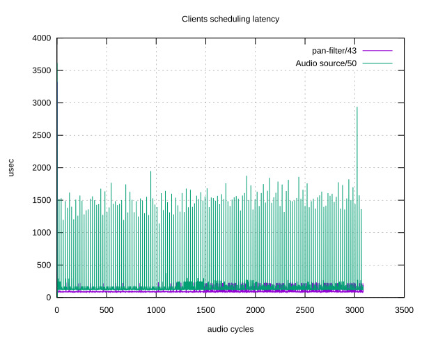
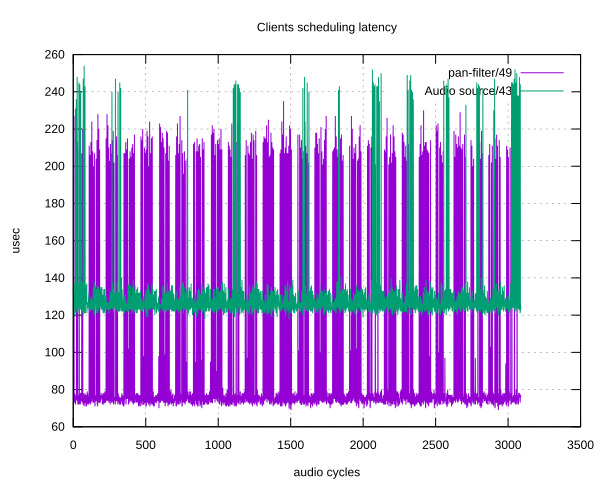
- Clients scheduling latency is the time from the client being scheduled to it starting running. This graph can highlight issues in your system’s IPC latencies.
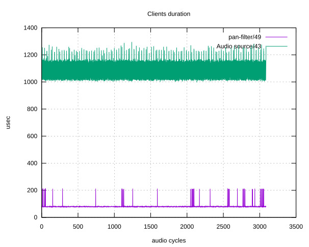
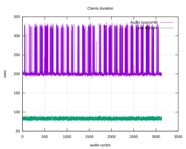
- Clients duration is the time for the client to run. It can highlight spikes in your node processing time.
Here is what the scheduling latency could look like in a setup with two nodes (a source and a filter), without and with the PREEMPT_RT patch:
Also, here is the impact of resampling on the clients duration (notice the legend, colors are inversed):
A remote patchbay
A tool type that is frequently useful is a patch-bay: it displays your graph as is, in a 2D plane, in real-time. It also allows you to modify it by deleting and creating links. Helvum is such a patch-bay software which is aimed at showing your local PipeWire instance. It can however be tricked into connecting to a remote instance using the following commands:
ssh $LOGIN@$IP "socat TCP4-LISTEN:8000 UNIX-CONNECT:/run/pipewire-0" &
socat UNIX-LISTEN:/tmp/pipewire-0 TCP4:$IP:8000 &
PIPEWIRE_RUNTIME_DIR=/tmp helvum
This requires the socat command on the board and our desktop. We link the local /tmp/pipewire-0 Unix socket through a TCP tunnel hosted by our board on port 8000, linked to the /run/pipewire-0 Unix socket.
That last file is the IPC that is created by the PipeWire daemon to allow clients to connect to it. As such, when we spawn Helvum by setting the PIPEWIRE_RUNTIME_DIR, it connects as a standard client to our remote PipeWire instance.
wpctl
Interactions with WirePlumber are to be done using the wpctl CLI tool. It allows one to get access to overall information using wpctl status. The main WirePlumber way of controlling to which output audio goes is through setting the default sink, which can be done using wpctl set-default $ID. The get-volume, set-volume and set-mute commands expose sound volume control. As an example, here is the command you would need to run to raise the current output volume by 10%: wpctl set-volume @DEFAULT_SINK@ 10%+.
Conclusion
We have therefore seen the PipeWire API through an example source, modified our kernel to implement a new input device which we used from our source to control the audio. We then did a rundown of the various tools that are useful when dealing with the PipeWire ecosystem.
Thank you so much for these pipewire articles.
Those really gave a proper insight.
Is for a connection between pjsua2 (SIP call) (https://github.com/pjsip/pjproject) and aes67-linux-daemon (AES67 stream) (https://github.com/bondagit/aes67-linux-daemon) nodes a custom node implementation also needed?
Both processes will create nodes in the PipeWire graph. What remains is to create links inbetween the two nodes, which can be done by relying on WirePlumber or manually. There is no need for a custom implementation.
In this case, both projects you shared seem to use the ALSA API, which is well supported. See pipewire-alsa/conf/ in the PW source code for a starting point.
Very informative sequence of articles! I’ll confess that much of it was over my head as this is my first attempt to dig into pipewire.
I could not help but wonder as I read through this: Is `bluez5` (and `bluetoothctl`) actually necessary for setting up a Bluetooth audio system?
I’d like to see more articles like these – perhaps one that walked a user through the setup and configuration of a Bluetooth speaker pair using `mpd` as a source.
Thanks for the kind note! It depends on how your Bluetooth chip is connected.
In both cases you need something in userspace for configuration of your chip. In the second case you also need something in userspace to extract the audio for you. BlueZ does both.
In theory, in the first case, you can remove BlueZ if you handle the communication with the chip by yourself, but I have never experimented with those kind of setups. Hoping it makes things clearer.