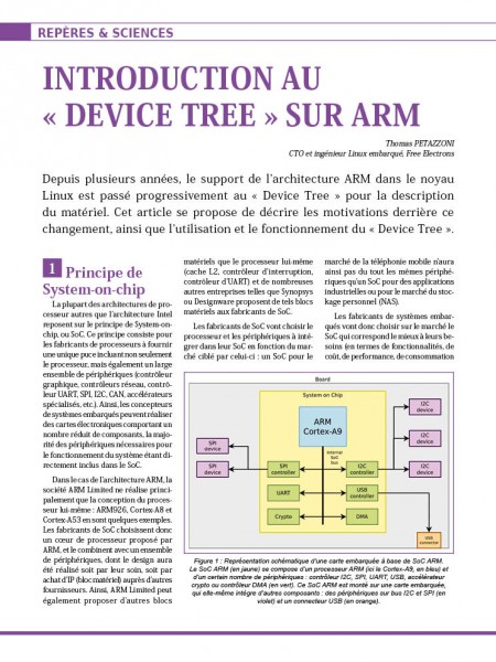
We recently had the chance to work on a customer project that involved the RaspberryPi Compute Module 3, with custom peripherals attached: a Microchip WILC1000 WiFi chip connected on SDIO, and a SGTL5000 audio codec connected over I2S/I2C. We take this opportunity to share some insights on how to introduce new hardware support on RaspberryPi platforms, by taking advantage of the Raspberry Pi specific Device Tree overlay mechanism.
Building and loading an upstream RPi Linux
Our customer is using the RaspberryPi OS Lite, which is a Debian-based system, coming with its pre-compiled Linux kernel image. However, for this project, we obviously need to customize the Linux kernel configuration, so we had to build our own kernel.
While Bootlin normally has a preference for using the upstream Linux kernel, for this project, we decided to keep using the Linux kernel fork provided by Raspberry Pi on Github, which is used by Raspberry Pi OS Lite. So we start our work by grabbing the Linux kernel source code from a the rpi-5.4.y provided by the Raspberry Pi Linux kernel repository:
$ git clone https://github.com/raspberrypi/linux -b rpi-5.4.y
After installing an appropriate ARM 32-bit cross-compilation toolchain, we’re ready to configure and build the kernel:
$ make ARCH=arm CROSS_COMPILE=arm-linux-gnueabihf- bcm2709_defconfig
$ make ARCH=arm CROSS_COMPILE=arm-linux-gnueabihf- -j4 zImage
Thanks to the USB mass storage mode of the Raspberry Pi it is quite straightforward to update the kernel as it allows to mount the board eMMC partitions on the host system, and update whichever files we want. The tool that actually sets the RaspberryPi in this mode is called rpiboot.
After executing it, we deploy the zImage into the RaspberryPi /media/${USER}/boot/ partition and update the file /media/${USER}/boot/config.txt to set the firmware directive kernel=zImage.
That’s all it takes to replace the kernel image provided by the RaspberryPi OS Lite system by our own kernel, which means we are now ready to integrate our new features.
Device Tree Overlays
A specificity of the Raspberry Pi is that the boot flow starts from the GPU core and not the ARM core like it does on most embedded processors. The GPU load a first bootloader from a ROM that will load a second bootloader (bootcode.bin) from eMMC/SD card that is in charge of executing a firmware (start.elf). This GPU firmware finally reads and parses a file stored in the boot partition (config.txt), which is used to set various boot parameters such as the image to boot on.
This config.txt file also allows to indicate which Device Tree file should be used as the hardware description, as well as Device Tree Overlays that should be applied on top of the Device Tree files. Device Tree Overlays are a bit like patches for the Device Tree: they allow to extend the base Device Tree with new properties and nodes. They are typically used to describe the hardware attached to the RaspberryPi through expansion boards.
The Raspberry Pi kernel tree contains a number of such Device Tree Overlays in the arch/arm/boot/dts/overlays folder. Each of those overlays, stored in .dts file gets compiled into a .dtbo files. Those .dtbo can be loaded and applied to the main Device Tree by adding the following statement to the config.txt file:
dtoverlay=overlay-name,overlay-arguments
We will fully take advantage of this mechanism to introduce two new Device Tree Overlays that will be parsed and dynamically merged into the main Device Tree.
WILC1000 WiFi chip Device Tree overlay
The ATWILC1000 we want to support is a Microchip WiFi module. As of the Linux 5.4 kernel we are using for this project, the driver for this WiFi chip was still in the staging area of the Linux kernel, in drivers/staging/wilc1000, but it more recently graduated out of staging. We obviously started by enabling this driver in the kernel configuration, through its CONFIG_WILC1000 and CONFIG_WILC1000_SDIO options.
To describe the WILC1000 module in terms of Device Tree, we need to create a arch/arm/boot/dts/overlays/wilc1000-overlays.dts file, with the following contents:
/dts-v1/;
/plugin/;

/ {
    compatible = "brcm,bcm2835";

    fragment@0 {
        target = <&mmc>;
        wifi_ovl: __overlay__ {
            pinctrl-0 = <&sdio_ovl_pins &wilc_sdio_pins>;
            pinctrl-names = "default";
            non-removable;
            bus-width = <4>;
            status = "okay";
            #address-cells = <1>;
            #size-cells = <0>;

            wilc_sdio: wilc_sdio@0 {
                compatible = "microchip,wilc1000", "microchip,wilc3000";
                irq-gpios = <&gpio 1 0>;
                status = "okay";
                reg = <0>;
                bus-width = <4>;
            };
        };
    };

    fragment@1 {
        target = <&gpio>;
        __overlay__ {
            sdio_ovl_pins: sdio_ovl_pins {
                brcm,pins = <22 23 24 25 26 27>;
                brcm,function = <7>; /* ALT3 = SD1 */
                brcm,pull = <0 2 2 2 2 2>;
            };

            wilc_sdio_pins: wilc_sdio_pins {
                brcm,pins = <1>; /* CHIP-IRQ */
                brcm,function = <0>;
                brcm,pull = <2>;
            };
        };
    };
};
To be compiled, this overlay needs to be referenced in arch/arm/boot/dts/overlays/Makefile.
This overlay contains two fragments: fragment@0 and fragment@1. Each fragment will extend a Device Tree node of the main Device Tree, which is specified by the target property of each fragment: fragment@0 will extend the node referenced by the &mmc phandle, and fragment@1 will extend the node referenced by the &gpio phandle. The mmc and gpio labels are defined in the main Device Tree describing the system-on-chip, arch/arm/boot/dts/bcm283x.dtsi. Practically speaking, the first fragment enables the MMC controller, its pin-muxing, and describes the WiFi chip as a sub-node of the MMC controller. The second fragment describes the pin-muxing configurations used for the MMC controller.
Above, each fragment target, &mmc and &gpio is matching an existing device node in the underlying tree arch/arm/boot/dts/bcm283x.dtsi. Note that our hardware is designed such as the reset pin of the wilc is automatically de-assert when powering the board so we don’t define it here.
Now that we have our overlay we enable it through the firmware config.txt :
dtoverlay=sdio,poll_once=off
dtoverlay=wilc1000
gpio=38=op,dh
In addition to our own wilc1000 overlay, we are also loading the sdio overlay, with the poll_once=off argument to make sure we are polling our wilc device even after the boot is complete when the chip enable gpio is asserted through the firmware directive gpio=38=op,dh.
After copying the wilc1000.dtbo on our board we can verify that both overlays are getting merged in the main device-tree using the vcdbg command:
  pi@raspberrypi:~$ sudo vcdbg log msg
   002351.555: brfs: File read: /mfs/sd/config.txt
   002354.107: brfs: File read: 4322 bytes
   ...
   005603.860: dtdebug: Opened overlay file 'overlays/wilc1000.dtbo'
   005605.500: brfs: File read: /mfs/sd/overlays/wilc1000.dtbo
   005619.506: Loaded overlay 'sdio'
   005624.063: dtdebug: fragment 3 disabled
   005624.160: dtdebug: fragment 4 disabled
   005624.256: dtdebug: fragment 5 disabled
   005633.283: dtdebug: merge_fragment(/soc/mmcnr@7e300000,/fragment@0/__overlay__)
   005633.308: dtdebug:   +prop(status)
   005633.757: dtdebug: merge_fragment() end
   005642.521: dtdebug: merge_fragment(/soc/mmc@7e300000,/fragment@1/__overlay__)
   005642.549: dtdebug:   +prop(pinctrl-0)
   005643.003: dtdebug:   +prop(pinctrl-names)
   005643.443: dtdebug:   +prop(non-removable)
   005644.022: dtdebug:   +prop(bus-width)
   005644.477: dtdebug:   +prop(status)
   005644.935: dtdebug: merge_fragment() end
   005646.614: dtdebug: merge_fragment(/soc/gpio@7e200000,/fragment@2/__overlay__)
   005650.499: dtdebug: merge_fragment(/soc/gpio@7e200000/sdio_ovl_pins,/fragment@22
   /__overlay__/sdio_ovl_pins)
   ...
Of course there are lots of other useful tools that we used to debug, such as raspi-gpio and dtoverlay:
 pi@raspberrypi:~$ sudo raspi-gpio get
   BANK0 (GPIO 0 to 27):
   GPIO 0: level=1 fsel=0 func=INPUT
   GPIO 1: level=1 fsel=0 func=INPUT
   GPIO 2: level=1 fsel=0 func=INPUT
   ...
   GPIO 22: level=0 fsel=7 alt=3 func=SD1_CLK
   GPIO 23: level=1 fsel=7 alt=3 func=SD1_CMD
   GPIO 24: level=1 fsel=7 alt=3 func=SD1_DAT0
   GPIO 25: level=1 fsel=7 alt=3 func=SD1_DAT1
   GPIO 26: level=1 fsel=7 alt=3 func=SD1_DAT2
   GPIO 27: level=1 fsel=7 alt=3 func=SD1_DAT3
Here we can actually see that the correct pinmuxing configuration is set for the SDIO pins.
Testing WiFi on RaspberryPi OS
During our test we found that the wilc1000 seems to only support one mode at time which means only STA or soft-AP. The first mode is quite straightforward to test using the raspi-config tool, we just had have to supply our SSID name and password.
To know which modes are supported and if they are supported simultaneously use iw list:
   pi@raspberrypi:~$ iw list
   Wiphy phy0
           max # scan SSIDs: 10
           max scan IEs length: 1000 bytes
           max # sched scan SSIDs: 0
           max # match sets: 0
           max # scan plans: 1
           max scan plan interval: -1
           max scan plan iterations: 0
           Retry short limit: 7
           Retry long limit: 4
           Coverage class: 0 (up to 0m)
           Supported Ciphers:
                   * WEP40 (00-0f-ac:1)
                   * WEP104 (00-0f-ac:5)
                   * TKIP (00-0f-ac:2)
                   * CCMP-128 (00-0f-ac:4)
                   * CMAC (00-0f-ac:6)
           Available Antennas: TX 0x3 RX 0x3
           Supported interface modes:
                    * managed
                    * AP
                    * monitor
                    * P2P-client
                    * P2P-GO
            ...
        software interface modes (can always be added):
        interface combinations are not supported
        Device supports scan flush.
        Supported extended features:
To use the wilc1000 in soft-AP mode, one need to install additional packages in the RaspberryPi OS, such as hostapd and dnsmasq.
SGTL5000 audio codec Device Tree Overlay
After integrating support for the WILC1000 WiFi chip, we can now look at how we got the SGTL5000 audio codec to work. We wrote an overlay arch/arm/boot/dts/overlays/sgtl5000-overlay.dts with the following contents, and also edited arch/arm/boot/dts/overlays/Makefile to ensure it is built. Our sgtl5000-overlay.dts contains:
/dts-v1/;
/plugin/;
/{
compatible = "brcm,bcm2835";
fragment@0 {
target-path = "/";
__overlay__ {
sgtl5000_mclk: sgtl5000_mclk {
compatible = "fixed-clock";
#clock-cells = <0>;
clock-frequency = <12288000>;
clock-output-names = "sgtl5000-mclk";
};
};
};
fragment@1 {
target = <&soc>;
__overlay__ {
reg_1v8: reg_1v8@0 {
compatible = "regulator-fixed";
regulator-name = "1V8";
regulator-min-microvolt = <1800000>;
regulator-max-microvolt = <1800000>;
regulator-always-on;
};
};
};
fragment@2 {
target = <&i2c1>;
__overlay__ {
status = "okay";
sgtl5000_codec: sgtl5000@0a {
#sound-dai-cells = <0>;
compatible = "fsl,sgtl5000";
reg = <0x0a>;
clocks = <&sgtl5000_mclk>;
micbias-resistor-k-ohms = <2>;
micbias-voltage-m-volts = <3000>;
VDDA-supply = <&vdd_3v3_reg>;
VDDIO-supply = <&vdd_3v3_reg>;
VDDD-supply = <®_1v8>;
status = "okay";
};
};
};
fragment@3 {
target = <&i2s>;
__overlay__ {
status = "okay";
};
};
fragment@4 {
target = <&sound>;
sound_overlay: __overlay__ {
compatible = "simple-audio-card";
simple-audio-card,format = "i2s";
simple-audio-card,name = "sgtl5000";
simple-audio-card,bitclock-master = <&dailink0_master>;
simple-audio-card,frame-master = <&dailink0_master>;
simple-audio-card,widgets =
"Microphone", "Microphone Jack",
"Speaker", "External Speaker";
simple-audio-card,routing =
"MIC_IN", "Mic Bias",
"External Speaker", "LINE_OUT";
status = "okay";
simple-audio-card,cpu {
sound-dai = <&i2s>;
};
dailink0_master: simple-audio-card,codec {
sound-dai = <&sgtl5000_codec>;
};
};
};
};
This is a much more complicated overlay, with a total of 5 fragments, which we will describe in detail:
fragment@0: this fragment adds a new Device Tree node that describes a clock that runs at a fixed frequency. Indeed, the sys_mclk clock of our codec is provided by an external oscillator running at 12.288 Mhz: this sgtl5000_mclk describes this external oscillator.fragment@1: this fragment defines an external power supply used as the VDDD-supply of the sgtl5000 codec. Indeed, this codec is simply power by an always-on power supply at 1.8V. Don’t forget to enable both kernel options CONFIG_REGULATOR=y and CONFIG_REGULATOR_FIXED_VOLTAGE=y otherwise the driver will just silently fail to probe at boot.fragment@2: this fragment describes the audio codec itself. The audio codec is described as a child of the I2C controller it is connected to: indeed the SGTL5000 uses I2C as its control interface.fragment@3: this fragment simply enables the I2S interface. The CONFIG_SND_BCM2835_SOC_I2S=y kernel option must be enabled to have the corresponding driver.fragment@4: this fragment describes the actual sound card. It uses the generic simple-audio-card driver, describes the two sides of the audio link: the CPU interface in the &i2s and the codec interface in the &sgtl_codec node, and describes the audio widgets and routes. See the simple-audio-card Device Tree binding
With this overlay in place, we need to enable it in the config.txt file, as well as the I2C1 overlay with a correct pin-muxing configuration:
dtparam=i2s=on
dtoverlay=sgtl5000
dtoverlay=i2c1,pins_2_3
# AUDIO_SD
gpio=40=op,dh
Once the system has booted, a new audio card is visible, and all the classic ALSA user-space utilities can be used: amixer to control the volume, aplay and arecord to play/record audio.
Conclusion
In this blog post, we have shown how Device Tree Overlays can easily be used to extend the description of the hardware, and enable the use of additional hardware devices on a Raspberry Pi system. Do not hesitate to contact us for support on Raspberry Pi platforms!
 Next week is going to be a busy week in Vienna, with the Open Source Summit Europe followed by the Linux Plumbers conference. As we had already published in a previous blog post, Bootlin will have a very strong presence at those events: 13 Bootlin engineers will participate to the Open Source Summit and 2 will give talks, and 8 Bootlin engineers will participate to Linux Plumbers.


