This year, the ELC will take place in Seatle but will be organised as a hybrid virtual/physical event due to the pandemic. As usual the ELC will have a really interesting schedule with 46 talks covering a wide range of topics: build system, kernel graphics, boot process, security, etc.
See below the details of Bootlin talks that will be presented as virtual talks.
Advanced Camera Support on Allwinner SoCs with Mainline Linux – Paul Kocialkowski, Bootlin
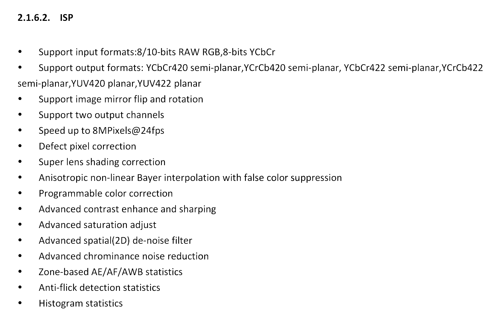
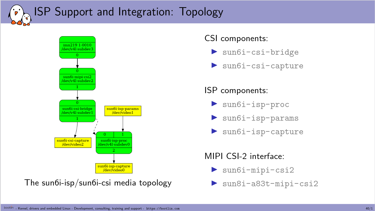
Capturing pixels with a camera involves a number of steps, from the ADC reading the photosites in the image sensor to the final pixel values that are ready for encode/display, with various processing and transmission taking place along the way. While simple cases put most of the heavy lifting on the image sensor’s side (through its embedded processor) and use a simple parallel bus for transmission, advanced cases require more work to be done outside of the sensor. In addition, modern high-speed transmission buses also bring-in more complexity. This talk will present how support for such an advanced use case was integrated into the mainline Linux kernel, using the Media and V4L2 APIs. It involves supporting a sensor using the raw Bayer RGB format, transmission over the MIPI CSI-2 bus as well as support for the Image Signal Processor (ISP) found on Allwinner platforms. A specific focus will be set on this ISP, with details about the features it implements as well as the internal and userspace APIs that are used to support it. The integration between all of the involved components will also be highlighted.
Embedded Linux Nuggets found in Buildroot Package Eldorado
To this date, Buildroot supports more than 2,500 packages, selected for the ability to run them on embedded Linux systems. We’ve gone exploring this Eldorado, and came back with multiple nuggets of all shapes and colors. Join this playful presentation and as if you were still a new comer to the embedded Linux community, discover lesser known tools and resources that can add to the functionality of your systems or make your life as a developer easier and more fun. Whenever possible, each resource will be shown through a quick demonstration or video capture. During this talk, I’ll also open an Etherpad for all participants to share their favorite solutions with the rest of the audience, especially the ones that deserve to be better known, and could be worth supporting in Buildroot too. We will close the session by an open review and discussion based on the nuggets shared by the audience.
I3C is the new bus specification by the MIPI Alliance. While being compatible with I2C devices, this bus brings a colorful set of new features such as dynamic address assignment, in-band interrupts, hot-join, master handover and many others. It was improved once again recently with the 1.1 version of the specification which brought timer based sampling synchronization and targeted reset. All this make the I3C bus a good candidate for a number of new situations compared to its I2C cousin. It is then more and more being included in new hardware designs. With this talk we would like to propose a reminder of the various components and concepts of this relatively new bus. We will then detail how it is implemented in the Linux kernel with a short guided tour in the I3C core. Since the previous talk on I3C in 2018 by Boris Brezillon, I3C has now become a reality and starts to become available in real hardware designs. This talk will recap the basics of I3C as well as add details of the 1.1 specification and improvements in the Linux support.
OP-TEE is an open-source Trusted Execution Environment designed to be executed in a secure context as a companion to a non secure Linux system. But what happens to the peripherals control since OP-TEE can forbid the non-secure OS to access them ? When running with a TEE, Linux isn’t in charge anymore of some critical peripherals and relies on the TEE to access and configure them. There are multiple protocols and methods to access these peripherals that are supported by Linux (SCMI, PSCI, SMC). Supporting them for a SoC requires understanding the various interactions between the systems and how to modify them to fit that new control scheme. Additionally, the configuration must be passed from OP-TEE to Linux to allow a seamless integration. This talk will cover the boot process to start a secure system and the modifications needed to run Linux when OP-TEE is in charge of some peripherals. The work that has been done for a specific SoC will be described to have a tangible real-world use-case.
GPIOs are obviously widely used in embedded systems, and many of them are typically driven directly by Linux kernel drivers for interrupt lines, reset lines, or other control lines used to connect with various peripherals. However, a number of GPIOs are sometimes directly driven by user-space applications. Historically, the Linux kernel has provided a sysfs interface, in /sys/class/gpio to allow such direct control. But in recent years, this sysfs interface has been superseded by a new user-space interface based on /dev/gpiochip* character devices.
This new interface has numerous advantages over the previous /sys/class/gpio interface. However, one drawback is that it creates one device file per GPIO chip, which means that access rights are defined per GPIO chip, and not per GPIOs.
For this reason, in Linux 5.8, Geert Uytterhoeven has contributed the GPIO aggregator mechanism. It allows to group a number of GPIOs into a virtual GPIO chip, visible as an additional /dev/gpiochip*. Its documentation can be found in Documentation/admin-guide/gpio/gpio-aggregator.rst.
The list of GPIOs part of this new virtual GPIO chip is defined in the Device Tree. One other interesting thing is that, as any GPIO controler, the lines can be named, and then queried by user-space applications based on their name, using the libgpiod library.
Configuration and Device Tree description
To have GPIO Aggregator support in your kernel, simply configure
CONFIG_GPIO_AGGREGATOR=y
Add a gpio-aggregator node in your Device Tree source. For instance, the following DTS snippet declares an aggregator with several GPIO lines:
In this example, line 4 of gpio controller gpio3 is used and is named “line_a”, line 4 of gpio controller gpio2 is used and is named “line_b”, and so on up to line 8 of gpio controler gpio3.
Usage from user-space
From userspace we can see the GPIO chip and its aggregated lines:
# gpioinfo
...
gpiochip6 - 7 lines:
line 0: "line_a" unused input active-high
line 1: "line_b" unused input active-high
line 2: "line_c" unused input active-high
line 3: "line_d" unused input active-high
line 4: "line_e" unused input active-high
line 5: "line_f" unused input active-high
line 6: "line_g" unused input active-high
...
We can search a gpio chip and a line number by the line name:
We can change the GPIO chip device file ownership to allow user or group to access the attached lines:
# ls -al /dev/gpiochip*
crw------- 1 root root 254, 0 Jan 1 00:00 /dev/gpiochip0
crw------- 1 root root 254, 1 Jan 1 00:00 /dev/gpiochip1
crw------- 1 root root 254, 2 Jan 1 00:00 /dev/gpiochip2
crw------- 1 root root 254, 3 Jan 1 00:00 /dev/gpiochip3
crw------- 1 root root 254, 4 Jan 1 00:00 /dev/gpiochip4
crw------- 1 root root 254, 5 Jan 1 00:00 /dev/gpiochip5
crw------- 1 root root 254, 6 Jan 1 00:00 /dev/gpiochip6
#
# chown root:users /dev/gpiochip6
# chmod 660 /dev/gpiochip6
# ls -al /dev/gpiochip*
crw------- 1 root root 254, 0 Jan 1 00:00 /dev/gpiochip0
crw------- 1 root root 254, 1 Jan 1 00:00 /dev/gpiochip1
crw------- 1 root root 254, 2 Jan 1 00:00 /dev/gpiochip2
crw------- 1 root root 254, 3 Jan 1 00:00 /dev/gpiochip3
crw------- 1 root root 254, 4 Jan 1 00:00 /dev/gpiochip4
crw------- 1 root root 254, 5 Jan 1 00:00 /dev/gpiochip5
crw-rw---- 1 root users 254, 6 Jan 1 00:00 /dev/gpiochip6
#
The GPIO chip created by the aggregator can be retrieved from sysfs:
# ls -1 /sys/bus/platform/devices/gpio-aggregator/
driver
driver_override
gpio
gpiochip6
modalias
of_node
power
subsystem
uevent
#
# cat /sys/bus/platform/devices/gpio-aggregator/gpiochip6/dev
254:6
#
Conclusion
A GPIO Aggregator can be used to group a subset of GPIO lines, name them, access them by their names and manage access control to the virtual gpio chip created by the aggregator. On an embedded system, this can simplify the management and usage of individual GPIO lines.
Yes, Linux 5.13 was released yesterday, but we never published the blog post detailing our contributions to Linux 5.12, so let’s do this now! First of all the usual links to the excellent LWN.net articles on the 5.12 merge window: part 1 and part 2.
LWN.net also published an article with Linux 5.12 development statistics, and two Bootlin engineers made their way to the statistics: Alexandre Belloni in the list of top contributors by number of changesets, with 69 commits, and Paul Kocialkowski in the list of top contributors by number of changed lines, with over 6000 lines changed.
Here are the highlights of our contributions:
Addition of a new driver for the SilvacoI3C master controller. This was contributed by Miquèl Raynal, who became the maintainer for this driver. Bootlin has pioneered support for I3C in Linux, by introducing the complete drivers/i3c subsystem a few years ago, together with the first controller driver, for a Cadence IP, see our blog post from 2018.
Implementation of mqprio support in the Marvell Ethernet controller driver mvneta, see this commit. As explained in the tc-mqprio man page, the MQPRIO qdisc is a simple queuing discipline that allows mapping traffic flows to hardware queue ranges using priorities and a configurable priority to traffic class mapping. This was contributed by Maxime Chevallier
Improvements in the IIO driver for the ms58xx family of sensors, contributed by Alexandre Belloni.
The final removal of the atmel_tclib code, which has been replaced by proper drivers for the TCB timers on Atmel/Microchip ARM platforms over the past few releases, also by Alexandre Belloni.
As usual, a large amount of fixes and improvements in the RTC subsystem, by its maintainer Alexandre Belloni.
Here is the detailed list of our contributions to this release:
The second edition of Live Embedded Event took place on June 3rd, exactly 6 months after the first edition. Even though there were a few issues with the online platform, it was once again great to learn new things about embedded, and share some of the work we’ve been doing at Bootlin on various topics. For the next edition, we plan to switch to a different online platform, hopefully providing a better experience.
But in the mean time, all videos of the event have been posted on the Youtube Channel of the event. The talks from Bootlin have been posted on Bootlin’s Youtube Channel.
Indeed, in addition to being part of the organization committee, Bootlin prepared and delivered 5 talks as part of Live Embedded Event, covering different topics we have worked on in the recent months for our customers.
Understanding U-Boot Falcon Mode and adding support for new boards, Michael Opdenacker
We have recently contributed support for NV-DDR interfaces to parallel NAND flashes in the Linux kernel, which brings performance improvements for a number of NAND flash devices. In this article, we will detail what are the ONFI specifications, the historical SDR interface, then the introduction of faster interfaces in the ONFI specification, and finally our work to support such interfaces in the Linux kernel.
ONFI specifications
Even though specifications came after the introduction of NAND devices on the market, the Open NAND Flash Interface (ONFI) specification is nowadays a de-facto specification which many NAND chip support (even non-ONFI ones). For instance, in the Linux kernel, we assume that any NAND flash device will by default, after a reset command, at least support the slowest set of ONFI timings. Other specifications exist, like the Joint Electron Device Engineering Council (JEDEC), but as it is a bit less common in the parallel NAND flashes world, we will focus on the ONFI details in this blog post.
The early days of the SDR interface
At the time of the first ONFI specification back in 2006, there was only a single interface detailed: the asynchronous data interface. Also known as Single Data Rate or SDR interface in modern language, it defines the timings sequence that should be respected in order for any NAND controller to be able to deal with almost any kind of NAND device. As an asynchronous interface, in this interface, the data bus has no clock signal. Instead, it features a specific set of signals which are asserted by the controller to signal read data latch and write data latch: Read Enable (RE#) and Write Enable (WE#).
The data interface can work in 6 different timing modes, from 0 to 5. 0 is the slowest mode and the default one at boot time with a theoretical data rate of about 10MiB/s (assuming an 8-bit bus). Mode 4 and 5 are the fastest, they leverage the ability of Extended Data Output (EDO) to latch data on both RE#/WE# edges and may reach a theoretical data rate of 50MiB/s.
The introduction of faster interfaces
Shortly after, at the beginning of 2008, the ONFI consortium released the second version of the ONFI specification and included a new interface: the source synchronous data interface. This interface is backward compatible with the asynchronous interface and allows the host to switch from one interface to the other if this is needed. In the particular case of the source synchronous interface, a clock (CLK) signal is replacing the legacy WE# signal and indicates when the commands and address should be latched. The direction of the transfers is handled by the Write/Read signal (W/R#) in place of RE# signal. Finally, a data strobe (DQS) signal is being introduced and indicates when the data should be latched. As both edges of the DQS signal advertise for a data latch, the source synchronous interface is also called Double Data Rate (DDR) interface even though this naming was only introduced in the version 3.0 of the specification, in 2011.
The exact terms that are used in more recent specifications are NV-DDR (Non-Volatile DDR), NV-DDR2 and NV-DDR3 which are backward compatible improvements of the NV-DDR interface. For instance, the first NV-DDR specification has a range of theoretical rates from 40MiB/s to 200MiB/s.
Support in the Linux kernel
While the addition of the MTD/NAND subsystem in the Linux kernel predates the Git era and is now over 20 years old, Linux users have always been limited to use the asynchronous interface (SDR modes). At Bootlin, we recently started an effort to bring support for the NV-DDR interface to the Linux kernel MTD/NAND subsystem, and this involved the following changes:
Introducing an API to propose timings to the host controller driver, so that it might either accept or refuse them (only SDR mode 0 cannot be refused) and be aware of all timings that this choice involves so that the host controller registers will be configured properly.
Adding the possibility for NAND chip drivers to tweak the timings if the parameter page is not present or inaccurate.
Adding the core logic to ask the NAND chip to change its data interface through the use of GET_FEATURE and SET_FEATURE calls, as well as verifying that this operation worked correctly and handling the fallback in case of error.
We recently reached a final step in this effort as the last missing parts will be part of the next Linux kernel release (v5.14). This final series aiming at bringing NV-DDR support to Linux carries the following changes:
Adding the necessary bits to parse the parameter page of the NAND device in order to know which NV-DDR modes the chips support.
Providing the reference implementation of all NV-DDR timing modes and various helpers to manage them.
Adding the necessary infrastructure and helpers to the host controller drivers in order to allow them to distinguish between SDR and NV-DDR, as well as advertise which mode they are willing to support based on the controller’s constraints.
Updating the existing logic to take into account the existence of NV-DDR timings and select them when appropriate. This part is a bit trickier as the core must gracefully fallback to SDR modes under certain conditions.
Overall, thanks to the major cleanups which happened in the NAND subsystem in the last three years, it was pretty straightforward to add support for these new timings.
Future work
It is worth mentioning that accelerating the overall throughput on the data bus without a deeper rework of the MTD core than just enabling faster timings is very limiting: data reads must respect a tR delay before starting and writes are considered effective only after a tPROG delay. Both are significantly high in practice: respectively about 25-45us and 200-600us, compared to the time needed to store/fetch the data through the I/O bus: a few dozens of micro-seconds.
To fully leverage the power of NV-DDR timings the NAND and MTD cores should be partially rewritten to bring parallel multi-die support and cached operations. Such features would allow to optimize the use of the I/O bus in order to mitigate the performances impact of tR and tPROG during massive I/O operations. This is precisely one of the tricks used by SSD drives to exhibit very fast I/Os while using multiple NAND chips behind. There is therefore interesting additional work to do in the Linux kernel MTD subsystem to fully benefit from NV-DDR interfaces.
The schedule for the next edition of Live Embedded Event has been published! This 100% online and free conference will take place on June 3rd, 2021. Thanks to the proposals received, the event will feature 4 tracks during the entire day, covering a wide range of topics: hardware for embedded systems, embedded Linux, RTOS, IoT, FPGA, RISC-V, and more.
Live Embedded Event #2 agenda
Bootlin is once again part of the organization team for this event, and in addition 5 talks proposed by Bootlin have been selected into the schedule. See below the details of our talks.
Understanding U-Boot Falcon Mode and adding support for new boards, Michael Opdenacker
The Falcon Mode is a U-Boot feature that allows to directly load the operating system kernel from the first stage of U-Boot (a.k.a. “SPL”), skipping the second stage of U-Boot. Doing this can save up to 1 second in the boot process, and this way, you can keep a full featured U-Boot that you can still fall back to for maintenance or development needs. However, using Falcon Mode is not always easy, as it requires extra code that most boards supported by U-Boot don’t have yet. At Bootlin, we had to add such support to U-Boot for several boards. This presentation will explain how Falcon Mode booting actually works in U-Boot and the implementation and usage choices made by U-Boot developers. It will show you how to add such Falcon Mode support to U-Boot for your own board.
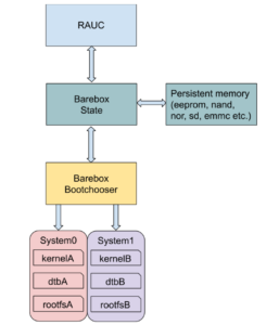
In embedded systems, deploying firmware updates in the field has now become an obvious requirement, to ensure that security vulnerabilities are addressed, that bugs are fixed, and new functionalities can be delivered to the users. Among a range of different open-source solutions, RAUC provides an interesting firmware update mechanism for embedded system. In this talk, we will introduce the main features of RAUC, its integration in build systems such as Buildroot or the Yocto Project, as well as its integration with the U-Boot and Barebox bootloaders. Finally we will explore some common update scenarios that are fully supported by RAUC features.
Talk given by Kamel Bouhara, at 3:30 PM CEST on June 3rd, 2021.
Security vulnerability tracking tools in Buildroot, Thomas Petazzoni
Buildroot is a popular and easy to use embedded Linux build system. With the increasing concern around security vulnerabilities affecting embedded systems, and the need to keep them updated, Buildroot has been extended with new tooling for security vulnerability tracking. This tooling allows to monitor the CVEs that affect the packages present in Buildroot. In this talk, we will introduce the principle of CVEs and CPEs, present the tools now available in Buildroot to help keep track of the security vulnerabilities, show how they can be used for a project and identify the current limitations of this tooling.
Talk given by Thomas Petazzoni, at 1:30 PM CEST on June 3rd, 2021.
Secure boot in embedded Linux systems, Thomas Perrot
Secure boot is a integrity mechanism, based on signature verification, that allows to detect software corruption or malicious code, during the boot process. Implementing secure boot is not always obvious, as it requires multiple stages of verification, at the bootloader, Linux kernel and root filesystem level, as well as integration into the build system, CI infrastructure, firmware upgrade mechanism, and more. Based on a recent experience to bring secure boot on an NXP i.MX8 platform, Thomas will present how to implement the chain of trust from the SoC ROM code to the root filesystem, as well as other considerations related to the implementation of secure boot. While the presentation will use the i.MX8 as an example, most of the discussion will apply to other platforms as well.
Talk given by Thomas Perrot, at 3:30 PM CEST on June 3rd, 2021.
Device Tree overlays and U-boot extension board management, Köry Maincent
In this talk, we will start by introducing the mechanism of Device Tree Overlays, which are a way of extending the Device Tree itself to describe additional hardware. We will show how Device Tree Overlays are written, compiled, and applied to a base Device Tree, and what is the status of Device Tree Overlays support in U-Boot and Linux. We will take the example of the BeagleBoard.org project, showing how Device Tree overlays are used to make CAPE extension boards compatible with different boards. Finally, we will describe our proposal, already submitted to the community, to add an extension board management facility to U-Boot, which automatically detects, loads and applies the appropriate Device Tree Overlays depending on the extension boards that are detected.
Talk given by Köry Maincent, at 1:30 PM CEST on June 3rd, 2021.
Bootlin recently received a beta prototype of the BeagleV Starlight featuring a RISC-V 64 bit SoC capable of running Linux, designed by StarFive This early version is not available to the general public, but several of us at Bootlin volunteered to join the beta developer program to assist with upstream software development. BeagleBoard.org has a public BeagleV forum that everyone can join for future updates on the project.
Two days after my colleague Thomas Petazzoni received his board, he managed to submit a patch for the mainline version of Buildroot to add support for this new board. Actually, compiling an image with Buildroot and preparing an SD card is easier than downloading and flashing the initial Fedora image offered for this beta board.
If you are just interested in testing the software on your board, you may directly get our binaries from our Build results paragraph.
The following instructions are derived from the board/beaglev/readme.txt file in Thomas’ proposed patch.
How to build
First, clone Buildroot’s git repository if you haven’t done it yet:
$ git clone git://git.buildroot.net/buildroot
Then add a remote branch corresponding to Thomas Petazzoni’s own tree, as his changes haven’t made their way into the mainline yet, and checkout a local copy of his beaglev branch:
After building, output/images should contain the following files:
Image
fw_payload.bin
fw_payload.bin.out
fw_payload.elf
rootfs.ext2
rootfs.ext4
sdcard.img
u-boot.bin
The two important files are:
fw_payload.bin.out, which is the bootloader image, containing both OpenSBI (the Open Supervisor Binary Interface, allowing to switch from Machine mode to Supervisor mode) and U-Boot.
sdcard.img, the SD card image, which contains the root filesystem, kernel image and Device Tree.
You just need to insert your micro SD card into a card reader (assuming the /dev/sdX device file is used), and type the below command:
$ sudo dd if=output/images/sdcard.img of=/dev/sdX
Preparing the board
To prevent the experimental board from overheating, connect the BeagleV fan to the 5V supply (pin 2 or 4 of the GPIO connector) and GND (pin 6 of the GPIO connector).
To access a serial console, connect a TTL UART cable to pins 6 (GND), 8 (TX) and 10 (RX):
Insert your SD card and power-up the board using a USB-C cable.
Flashing the bootloader
The bootloader pre-flashed on the BeagleV has a non-working fdt_addr_r environment variable value, so it won’t work as-is. Reflashing the existing bootloader with the bootloader image produced by Buildroot is therefore necessary.
When the board starts up, a pre-loader shows a count down of 2 seconds. Interrupt it by pressing any key. You should then reach a menu like
this:
bootloader version:210209-4547a8d
ddr 0x00000000, 1M test
ddr 0x00100000, 2M test
DDR clk 2133M,Version: 210302-5aea32f
0
***************************************************
*************** FLASH PROGRAMMING *****************
***************************************************
0:update uboot
1:quit
select the function:
Press 0 and Enter. You will now see C characters being displayed. Ask your serial port communication program to send the fw_payload.bin.out file using the Xmodem protocol (with the sx command). For example, here’s how to do it with picocom…
picocom should be started as:
$ picocom -b 115200 -s "sx -vv" /dev/ttyUSB0
When you see the C characters on the serial line, press [Ctrl][a] [Ctrl][s]. Picocom will then ask for a file name, and you should type fw_payload.bin.out.
After a few minutes, reflashing should be complete. Then, restart the board. It will automatically start the system from the SD card, and reach the login prompt:
Welcome to Buildroot
buildroot login: root
# uname -a
Linux buildroot 5.10.6 #2 SMP Sun May 2 17:23:56 CEST 2021 riscv64 GNU/Linux
Useful resources
Here are useful resources for people who already have the Beagle V board:
BeagleBoard’s beaglev-starlight: GitHub repository containing hardware design files, links to source code repositories (Linux, U-Boot, OpenSBI…) and useful documentation.
Typical embedded Linux systems include a wide number of software components, which all need to be compiled and integrated together. Two main approaches are used in the industry to integrate such embedded Linux systems: build systems such as Yocto/OpenEmbedded, Buildroot or OpenWrt, and binary distributions such as Debian, Ubuntu or Fedora. Of course, both options have their own advantages and drawbacks.
One of the benefits of using standard binary distributions such as Debian or Ubuntu is their widespread use, their serious and long-term security maintenance and their large number of packages. However, they often lack appropriate tools to automate the process of creating a complete Linux system image that combines existing binary packages and custom packages.
In this blog post, we introduce ELBE (Embedded Linux Build Environment), which is a build system designed to build Debian distributions and images for the embedded world. While ELBE was initially focused on Debian only, Bootlin contributed support for building Ubuntu images with ELBE, and this blog post will show as an example how to build an Ubuntu image with ELBE for a Raspberry Pi 3B.
ELBE base principle
When you first run ELBE, it creates a Virtual Machine (VM) for building root filesystems. This VM is called initvm. The process of building the root filesystem for your image is to submit and XML file to the initvm, which triggers the building of an image.
The ELBE XML file can contain an archive, which can contain configuration files, and additional software. It uses pre-built software in the form of Debian/Ubuntu packages (.deb). It is also possible to use custom repositories to get special packages into the root filesystem. The resulting root file system (a customized Debian or Ubuntu distribution) can still be upgraded and maintained through Debian’s tools such as APT (Advanced Package Tool). This is the biggest difference between ELBE and other build systems like the Yocto Project and Buildroot.
Bootlin contributions
As mentioned in this blog post introduction, Bootlin contributed support for building Ubuntu images to ELBE, which led to the following upstream commits:
We need to use the v13.2 version because our latest contributions for Ubuntu support made it to 13.2:
$ cd elbe
$ git checkout v13.2
To create the initvm:
$ PATH=$PATH:$(pwd)
$ elbe initvm create --devel
The --devel parameter allows to use ELBE from the current working directory into the initvm.
If the command fails with the Signature with unknown key: message you need to add these keys to apt. Use the following command where XXX is the key to be added:
Creating your initvm should take at least 10 to 20 minutes.
In case you rebooted your computer or stopped the VM, you will need to start it:
$ elbe initvm start
Create an ELBE project for our Ubuntu image.
To begin with, we will base our image on the armhf-ubuntu example. We create an ELBE pbuilder project and not a simple ELBE project because we later want to build our own Linux kernel package for our board:
The project identifier is written to rpi.prj. We save the identifier to a shell variable to simplify the next ELBE commands:
$ PRJ=$(cat rpi.prj)
Build the Linux package
As explained earlier we want to use ELBE to build our package for the Linux kernel. ELBE uses the standard Debian tool pbuilder to build packages. Therefore, we need to have debianized sources (i.e sources with the appropriate Debian metadata in a debian/ subfolder) to build a package with pbuilder.
First clone the Linux repositories:
$ git clone -b rpi-5.10.y https://github.com/raspberrypi/linux.git
$ cd linux
Debianize the Linux repositories. We use the elbe debianize command to simplify the generation of the debian folder:
$ elbe debianize
Fill the settings in the UI as follows (make sure you reduce the font size if you don’t see the Confirm button):
Make sure you set Name to rpi. Otherwise, you won’t get the output file names we use in the upcoming instructions.
The debianize command helps to create the skeleton of the debian folder in the sources. It has been pre-configured for a few packages like bootloaders or the Linux kernel, to create the rules to build these packages. It may need further modifications to finish the packaging process. Take a look a the manual to have more information on debianization. In our case, we need to tweak the debian/ folder with the two following steps to cross-build the Raspberry Linux kernel without error.
Append the below lines to the debian/rules file (use tabs instead of spaces):
According to how fast your system is, this can run for hours!
If everything ends well without error the out/ directory has been filled with output files:
$ ls ../out
linux-5.10-rpi_1.0_armhf.buildinfo
linux-5.10-rpi_1.0_armhf.changes
linux-5.10-rpi_1.0.dsc
linux-5.10-rpi_1.0.tar.gz
linux-headers-5.10-rpi_1.0_armhf.deb
linux-image-5.10-rpi_1.0_armhf.deb
linux-libc-dev-5.10-rpi_1.0_armhf.deb
Update the Ubuntu XML image description
Now we have our Linux kernel packaged we can move on to the image generation. Since we started from examples/armhf-ubuntu.xml, we will modify this file to fit our needs.
We begin by adding the Linux kernel package to the XML image description in the pkg-list node:
...
linux-image-5.10-rpi
...
We also have to add the Device Tree to the boot/ directory because the Linux kernel package installs all the Device Trees into the /usr/lib directory.
This change is part of the rootfs modifications, therefore it is described under the finetuning XML node. We also rename the kernel image to kernel.img:
We want to use an SD card on our Raspberry Pi, so we have to describe the partitioning of our image. For this purpose, we add the images and the fstab XML nodes to the target XML node:
The Raspberry Pi board also needs firmware binaries and configurations file to boot properly. We will use the overlay directory to add these Raspberry firmware files to the image:
To tell ELBE that the XML file has changed, you need to send it to the initvm:
$ elbe control set_xml $PRJ examples/armhf-ubuntu.xml
Then build the image with ELBE:
$ elbe control build $PRJ
$ elbe control wait_busy $PRJ
Finally, if the build completes successfully, you can retrieve the image file from the initvm:
$ elbe control get_files $PRJ
$ elbe control get_file $PRJ sdcard.img.tar.gz
Now you can flash the SD card image:
$ tar xf sdcard.img.tar.gz
$ dd if=sdcard.img of=/dev/sdX bs=1M
And boot the board with root and foo as login and password:
Ubuntu 18.04.1 LTS myUbuntu ttyAMA0
myUbuntu login: root
Password:
Welcome to Ubuntu 18.04.1 LTS (GNU/Linux 5.10-rpi armv7l)
* Documentation: https://help.ubuntu.com
* Management: https://landscape.canonical.com
* Support: https://ubuntu.com/advantage
The programs included with the Ubuntu system are free software;
the exact distribution terms for each program are described in the
individual files in /usr/share/doc/*/copyright.
Ubuntu comes with ABSOLUTELY NO WARRANTY, to the extent permitted by
applicable law.
root@myUbuntu:~#
Note: Ubuntu cannot be built for Raspberry A, B, B+, 0 and 0W according to https://wiki.ubuntu.com/ARM/RaspberryPi, as Ubuntu targets the ARMv7-A architecture, while the older RaspberryPi use an ARMv6 processor.
Further details
You can find our talk about ELBE at the ELCE 2020 conference: PDF slides, video.
The Linux Test Project is a project that develops and maintains a large test suite that helps validating the reliability, robustness and stability of the Linux kernel and related features. LTP has been mainly developed by companies such as IBM, Cisco, Fujitsu, SUSE, RedHat, with a focus on desktop distributions.
On the embedded side, both the openembedded-core Yocto layer and Buildroot have packages that allow to use LTP on embedded targets. However, for a recent project, we practically tried to run the full LTP test suite on an i.MX8 based platform running a Linux system built with Yocto. It turned out that LTP was apparently not very often tested on Busybox-based embedded systems, and we faced a number of issues. In addition to reporting various bugs/issues to the upstream LTP project, we also contributed a number of fixes and improvements:
Our contributions received a very warm welcome in the LTP community, which turned out to be very open and responsive. We hope that these contributions will encourage others to use LTP, and hopefully to make sure it continues to work on embedded platforms.
Quick start guide
At the time of this writing, LTP has more than 3800 tests written by the community, including about 1000 network-related tests. The tests are grouped together in categories described by files in the runtest/ folder. Based on this, two scenarios of tests are defined: default and network which are described by two files in the scenario_groups/ folder. These two scenarios simply list the categories of tests that need to be executed.
Here are the contents of the default and network:
$ cat scenario_groups/default
syscalls
fs
fs_perms_simple
fsx
dio
io
mm
ipc
sched
math
nptl
pty
containers
fs_bind
controllers
filecaps
cap_bounds
fcntl-locktests
connectors
power_management_tests
hugetlb
commands
hyperthreading
can
cpuhotplug
net.ipv6_lib
input
cve
crypto
kernel_misc
uevent
Once you have LTP built and installed on your board thanks to the appropriate OpenEmbedded or Buildroot package, you can run these two scenarios of test with the following commands (-n specify the network one):
$ cd /opt/ltp
$ ./runltp
$ ./runltp -n
Then take a look at the content of the result and the output directories.
For more information on building or running LTP please read this readme.
Since March 1st, 2021, we’re happy to have an additional engineer, Hervé Codina, in our engineering team based in Toulouse, France.
Hervé has 20 years’ experience working in embedded systems, both bare-metal systems and embedded Linux systems, in a wide range of applications. Hervé has experience working with U-Boot, Barebox, Linux, Buildroot, Yocto, on ARM platforms from various silicon vendors. Hervé will work within our engineering team to deliver ready-to-use Linux Board Support Packages, port bootloaders and the Linux kernel to new platforms, develop Linux kernel device drivers, implement custom Linux systems with Buildroot or Yocto, and more. His 20 years experience will further increase the expertise that Bootlin provides to its worldwide customers.