Another system update adventure with RAUC, Barebox & Yocto Project

After experiencing both SWupdate and Mender in the past we recently got the opportunity to work with another update framework for embedded systems called RAUC.

This time the choice of RAUC as system upgrade framework was mainly motivated by the Phytec IMX6 board ecosystem which is based on both Barebox and Yocto Project.
Indeed RAUC and Barebox are both developed by Pengutronix and both are designed to provide a complete and homogeneous solution that will be introduced in this post.

Adding RAUC support in Barebox

RAUC relies on the bootchooser mechanism implemented in
Barebox which provides a mean to work with abstract boot targets:

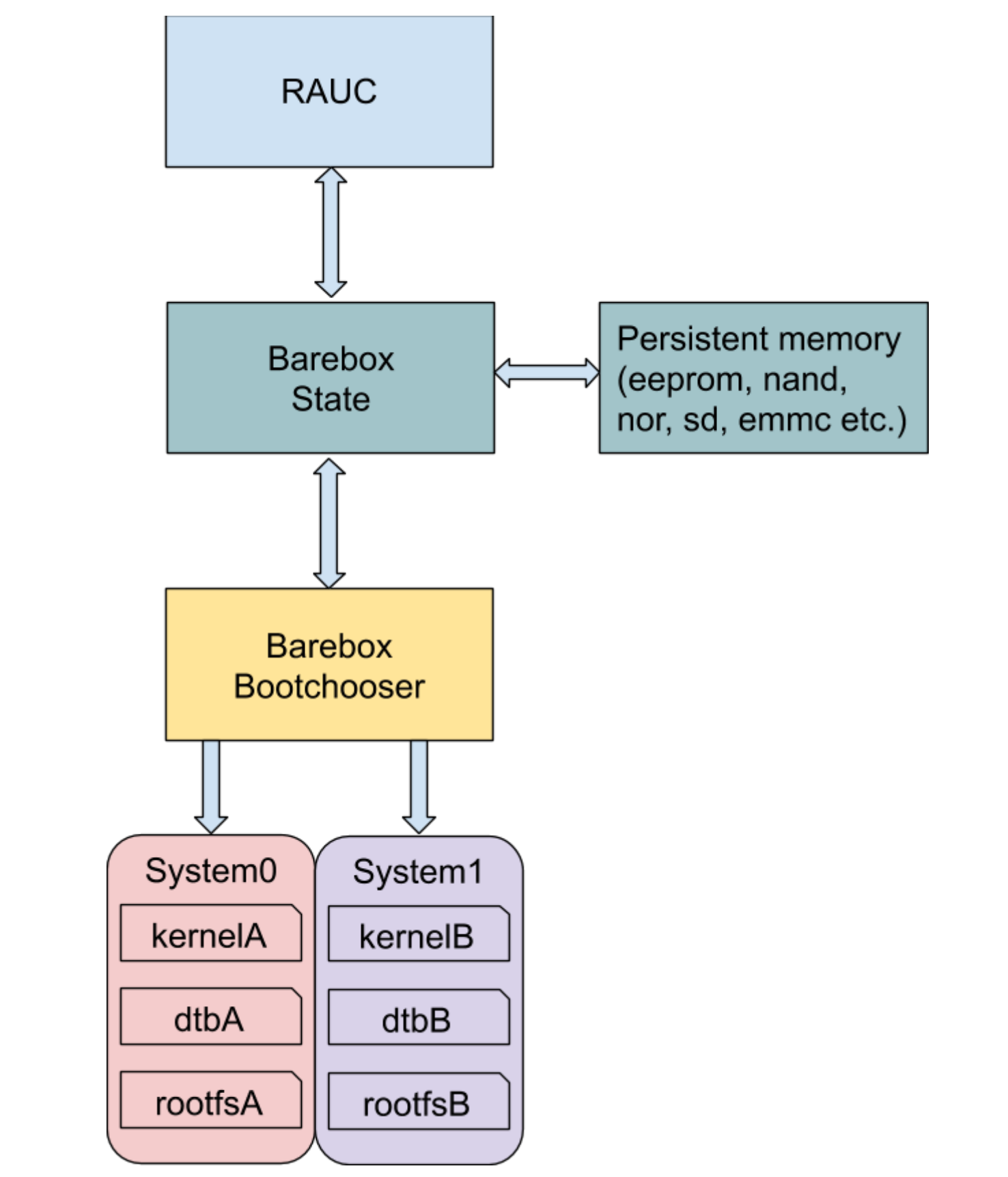
A target can be seen as set of variables and options that will be used by the bootchooser algorithm to choose which target to boot on.
The way those variables are presented and accessed is defined in the Barebox state framework which stores them in persistent memory (EEPROM, NAND/NOR flash, SD/eMMC, etc.).

In our case the state Device Tree below was already described by the Phytec BSP in the board EEPROM:

/ {
        aliases {
                state = &state;
        };

        state: imx6qdl_phytec_boot_state {
                magic = <0x883b86a6>;
                compatible = "barebox,state";
                backend-type = "raw";
                backend = <&backend_update_eeprom>;
                backend-storage-type = "direct";
                backend-stridesize = <54>;

                #address-cells = <1>;
                #size-cells = <1>;
                bootstate {
                        #address-cells = <1>;
                        #size-cells = <1>;
                        last_chosen {
                                reg = <0x0 0x4>;
                                type = "uint32";
                        };
                        system0 {
                                #address-cells = <1>;
                                #size-cells = <1>;
                                remaining_attempts {
                                        reg = <0x4 0x4>;
                                        type = "uint32";
                                        default = <3>;
                                };
                                priority {
                                        reg = <0x8 0x4>;
                                        type = "uint32";
                                        default = <21>;
                                };
                                ok {
                                        reg = <0xc 0x4>;
                                        type = "uint32";
                                        default = <0>;
                                };
                        };
                        system1 {
                                #address-cells = <1>;
                                #size-cells = <1>;
                                remaining_attempts {
                                        reg = <0x10 0x4>;
                                        type = "uint32";
                                        default = <3>;
                                };
                                priority {
                                        reg = <0x14 0x4>;
                                        type = "uint32";
                                        default = <20>;
                                };
                                ok {
                                        reg = <0x18 0x4>;
                                        type = "uint32";
                                        default = <0>;
                                };
                        };
                };
        };
};

&eeprom {
        status = "okay";
        partitions {
                compatible = "fixed-partitions";
                #size-cells = <1>;
                #address-cells = <1>;
                backend_update_eeprom: state@0 {
                        reg = <0x0 0x100>;
                        label = "update-eeprom";
                };
        };
};

Most of the properties are very well documented here.

This Device Tree defines a redundant A/B system upgrade scheme which matches our project requirement, we will just make sure to report remaining_attempts and priority values to the Barebox bootchooser variables that we will add later. For now we have to include the Device Tree in our board Device Tree by adding #include "imx6qdl-phytec-state.dtsi".

As we just added our state backend storage we have to enable both bootchooser and state framework in our barebox configuration:

CONFIG_STATE=y
CONFIG_STATE_DRV=y
CONFIG_CMD_STATE=y
CONFIG_BOOTCHOOSER=y
CONFIG_CMD_BOOTCHOOSER=y

We also have to add the boot targets system0 and system1 (as defined in the state Device Tree) in our default environment.
In Barebox source we create a default environment for our board in arch/arm/<board>/env with two boot entries, respectively arch/arm/<board>/env/boot/system0 and arch/arm/<board>/env/boot/system1.

Both have same contents except for the root filesystem partition name A/B:

#!/bin/sh

[ ! -e /dev/nand0.root.ubi ] && ubiattach /dev/nand0.root

mkdir -p /mnt/nand0.root.ubi.rootfsA
automount -d /mnt/nand0.root.ubi.rootfsA 'mount nand0.root.ubi.rootfsA'

global.bootm.oftree="/mnt/nand0.root.ubi.rootfsA/boot/imx6q-phytec-mira-rdk-nand.dtb"
global.bootm.image="/mnt/nand0.root.ubi.rootfsA/boot/zImage"
global.linux.bootargs.dyn.root="root=ubi0:rootfsA ubi.mtd=root rootfstype=ubifs rw"

In this configuration each partition holds its own Linux kernel image and Device Tree and the creation of the two UBIFS volumes system0/rootfsA and system1/rootfsB will be done by a factory process script.

Now we have to add bootchooser variables associated to both targets in arch/arm/<board>/env/nv directory we add following entries:

├── nv
│   ├── bootchooser.disable_on_zero_attempts
│   ├── bootchooser.reset_attempts
│   ├── bootchooser.reset_priorities
│   ├── bootchooser.retry
│   ├── bootchooser.state_prefix
│   ├── bootchooser.system0.boot
│   ├── bootchooser.system0.default_attempts
│   ├── bootchooser.system0.default_priority
│   ├── bootchooser.system1.boot
│   ├── bootchooser.system1.default_attempts
│   ├── bootchooser.system1.default_priority
│   ├── bootchooser.targets
│   ├── boot.default

The actual boot selection will be done by the bootchooser so we must set boot.default=bootchooser and targets="system0 system1".
We set a higher boot priority for system0 with variable system0.default_priority=21 over system1 with system1.default_priority=20.
We want the board to always boot on a target which means setting disable_on_zero_attempts=0 and finally we must set variable state_prefix="state.bootstate" so that the bootchooser can use our state variables stored in eeprom.

At this point we have completed the Barebox preparation and are ready to test it with RAUC.

From the Linux kernel configuration point of view we only need to add support for the SquashFS filesystem by enabling the CONFIG_SQUASHFS=y option.

Note that during our test we faced an issue with the kernel nvmem subsystem and the EEPROM. It seems that EEPROM partitions are not handled by the nvmem kernel driver because of the current binding that impose a reg property for each subnode to define a range address. The issue produces the following kernel trace at boot:

[    2.065648] nvmem 2-00500: nvmem: invalid reg on /soc/aips-bus@2100000/i2c@21a8000/eeprom@50/partitions

Due to this, from userspace, the barebox-state tool can not read the eeprom:

      root@miraq6-3d:~# barebox-state
      Cannot find backend path in /imx6qdl_phytec_boot_state

Thanks to Ahmad Fatoum we’ve been able to fix this behavior with the patch series he submitted to the Linux kernel at https://lkml.org/lkml/2020/4/28/411.

Yocto integration

Adding RAUC support to our Yocto BSP is quite straightforward, we just add the meta-rauc layer:

$ git clone git://github.com/rauc/meta-rauc
$ bitbake-layers add-layer meta-rauc

Now we create a bundle image recipe recipes-core/bundles/bootlin-bundle.bb for our RAUC updates. The bundle images are the ones that RAUC can deploy on the target for system upgrades.

inherit bundle

RAUC_BUNDLE_COMPATIBLE = "bootlin"
RAUC_BUNDLE_SLOTS = "rootfs"
RAUC_SLOT_rootfs = "bootlin-image"

RAUC_KEY_FILE = "${YOCTOROOT}/keys/bootlindev.key.pem"
RAUC_CERT_FILE = "${YOCTOROOT}/keys/bootlindev.cert.pem"

The bundle image is a SquashFS filesystem composed with the root filesystem image, a manifest and the signature. At this time, RAUC supports two types of bundle formats: plain and a new format called verity that allows authentication of the installed filesystem.

Here the RAUC_SLOT_rootfs must correspond to an existing image in your BSP layer. RAUC allow signing and verifying bundle image with OpenSSL certificates provided by RAUC_CERT_FILE.

Next step, we add a configuration file in recipes-core/rauc/files/system.conf that will define the RAUC configuration on the target:

[system]
compatible=bootlin
bootloader=barebox

[keyring]
path=bootlindev.cert.pem

[slot.rootfs.0]
device=/dev/ubi0_0
type=ubifs
bootname=system0

[slot.rootfs.1]
device=/dev/ubi0_1
type=ubifs
bootname=system1

The bootname for each slot must correspond to those defined in the state Device Tree and bootchooser targets.

After that we append to the rauc recipe using a bbappend such as recipes-core/rauc/rauc_%.bbappend to install our own RAUC configuration:

FILESEXTRAPATHS_prepend := "${THISDIR}/files:"

SRC_URI += "file://system.conf"

We also have to add the rauc client package to our target image with IMAGE_INSTALL += "rauc" and we’re now ready to create our bundle image and test it:

$ bitbake bootlin-bundle

On the target we can start by checking our bundle image:

root@miraq6-3d:~# rauc info bootlin-bundle-miraq6-3d.raucb
rauc-Message: 11:27:53.354: Reading bundle: bootlin-bundle-miraq6-3d.raucb
rauc-Message: 11:27:53.544: Verifying bundle...
Compatible:     'bootlin'
Version:        '1.0'
Description:    'bootlin-bundle version 1.0-r0'
Build:          '20200724101202'
Hooks:          ''
1 Image:
(1)     bootlin-image-miraq6-3d.tar.gz
        Slotclass: rootfs
        Checksum:  4d3be002d7d5f4c8d4cf9d8ca7190a2b09b43ff7300943f8e9cdbcbc43c59508
        Size:      111438905
        Hooks:
0 Files

Certificate Chain:
 0 Subject: /O=rauc Inc./CN=rauc-demo
   Issuer: /O=rauc Inc./CN=rauc-demo
   SPKI sha256: 18:77:3D:06:CE:63:59:AC:CC:41:87:A4:CD:14:E3:52:DA:AB:4D:BE:F5:3B:6C:06:2F:D2:0B:E2:C8:8F:08:0E
   Not Before: Jul 21 07:32:37 2020 GMT
   Not After:  Aug 20 07:32:37 2020 GMT

Note that the target time must be set to allow the signature verification.

If the bundle image is correct we can launch the RAUC update process:

root@miraq6-3d:~# rauc install bootlin-bundle-miraq6-3d.raucb -d
rauc-Message: 11:06:01.505: Debug log domains: 'rauc'
(rauc:464): rauc-DEBUG: 11:06:01.522: install started
(rauc:464): rauc-DEBUG: 11:06:01.522: input bundle: bootlin-bundle-miraq6-3d.raucb
(rauc:464): rauc-DEBUG: 11:06:01.606: Trying to contact rauc service
installing
0% Installing
0% Determining slot states
20% Determining slot states done.
20% Checking bundle
20% Verifying signature
40% Verifying signature done.
40% Checking bundle done.
40% Loading manifest file
60% Loading manifest file done.
60% Determining target install group
80% Determining target install group done.
80% Updating slots
80% Checking slot rootfs.1
90% Checking slot rootfs.1 done.
90% Copying image to rootfs.1
...
100% Copying image to rootfs.1 done.

After reboot we finally check the RAUC boot status:

root@miraq6-3d:~# rauc status
=== System Info ===
Compatible:  bootlin
Variant:
Booted from: rootfs.1 (system1)

=== Bootloader ===
Activated: rootfs.0 (system0)

Note that in this example we only use the RAUC CLI client but you can also use the D-Bus API or the rauc-hawkbit client interfacing with hawkBit
webserver.

Conclusion

This RAUC integration allows us to achieve our system upgrade framework tour and we can say that this project compares very well with other system upgrade frameworks.
Indeed the fact that Barebox and RAUC are both developed by Pengutronix helps a lot for the integration but it is also well supported in U-Boot and doesn’t need much more than a boot script to integrate RAUC on it at least for a simple A/B upgrade strategy.

Enabling new hardware on Raspberry Pi with Device Tree Overlays

We recently had the chance to work on a customer project that involved the RaspberryPi Compute Module 3, with custom peripherals attached: a Microchip WILC1000 WiFi chip connected on SDIO, and a SGTL5000 audio codec connected over I2S/I2C. We take this opportunity to share some insights on how to introduce new hardware support on RaspberryPi platforms, by taking advantage of the Raspberry Pi specific Device Tree overlay mechanism.

Building and loading an upstream RPi Linux

Our customer is using the RaspberryPi OS Lite, which is a Debian-based system, coming with its pre-compiled Linux kernel image. However, for this project, we obviously need to customize the Linux kernel configuration, so we had to build our own kernel.

While Bootlin normally has a preference for using the upstream Linux kernel, for this project, we decided to keep using the Linux kernel fork provided by Raspberry Pi on Github, which is used by Raspberry Pi OS Lite. So we start our work by grabbing the Linux kernel source code from a the rpi-5.4.y provided by the Raspberry Pi Linux kernel repository:

$ git clone https://github.com/raspberrypi/linux -b rpi-5.4.y

After installing an appropriate ARM 32-bit cross-compilation toolchain, we’re ready to configure and build the kernel:

$ make ARCH=arm CROSS_COMPILE=arm-linux-gnueabihf- bcm2709_defconfig
$ make ARCH=arm CROSS_COMPILE=arm-linux-gnueabihf- -j4 zImage

Thanks to the USB mass storage mode of the Raspberry Pi it is quite straightforward to update the kernel as it allows to mount the board eMMC partitions on the host system, and update whichever files we want. The tool that actually sets the RaspberryPi in this mode is called rpiboot.

After executing it, we deploy the zImage into the RaspberryPi /media/${USER}/boot/ partition and update the file /media/${USER}/boot/config.txt to set the firmware directive kernel=zImage.

That’s all it takes to replace the kernel image provided by the RaspberryPi OS Lite system by our own kernel, which means we are now ready to integrate our new features.

Device Tree Overlays

A specificity of the Raspberry Pi is that the boot flow starts from the GPU core and not the ARM core like it does on most embedded processors. The GPU load a first bootloader from a ROM that will load a second bootloader (bootcode.bin) from eMMC/SD card that is in charge of executing a firmware (start.elf). This GPU firmware finally reads and parses a file stored in the boot partition (config.txt), which is used to set various boot parameters such as the image to boot on.

This config.txt file also allows to indicate which Device Tree file should be used as the hardware description, as well as Device Tree Overlays that should be applied on top of the Device Tree files. Device Tree Overlays are a bit like patches for the Device Tree: they allow to extend the base Device Tree with new properties and nodes. They are typically used to describe the hardware attached to the RaspberryPi through expansion boards.

The Raspberry Pi kernel tree contains a number of such Device Tree Overlays in the arch/arm/boot/dts/overlays folder. Each of those overlays, stored in .dts file gets compiled into a .dtbo files. Those .dtbo can be loaded and applied to the main Device Tree by adding the following statement to the config.txt file:

dtoverlay=overlay-name,overlay-arguments

We will fully take advantage of this mechanism to introduce two new Device Tree Overlays that will be parsed and dynamically merged into the main Device Tree.

WILC1000 WiFi chip Device Tree overlay

The ATWILC1000 we want to support is a Microchip WiFi module. As of the Linux 5.4 kernel we are using for this project, the driver for this WiFi chip was still in the staging area of the Linux kernel, in drivers/staging/wilc1000, but it more recently graduated out of staging. We obviously started by enabling this driver in the kernel configuration, through its CONFIG_WILC1000 and CONFIG_WILC1000_SDIO options.

To describe the WILC1000 module in terms of Device Tree, we need to create a arch/arm/boot/dts/overlays/wilc1000-overlays.dts file, with the following contents:

/dts-v1/;
/plugin/;

/ {
    compatible = "brcm,bcm2835";

    fragment@0 {
        target = <&mmc>;
        wifi_ovl: __overlay__ {
            pinctrl-0 = <&sdio_ovl_pins &wilc_sdio_pins>;
            pinctrl-names = "default";
            non-removable;
            bus-width = <4>;
            status = "okay";
            #address-cells = <1>;
            #size-cells = <0>;

            wilc_sdio: wilc_sdio@0 {
                compatible = "microchip,wilc1000", "microchip,wilc3000";
                irq-gpios = <&gpio 1 0>;
                status = "okay";
                reg = <0>;
                bus-width = <4>;
            };
        };
    };

    fragment@1 {
        target = <&gpio>;
        __overlay__ {
            sdio_ovl_pins: sdio_ovl_pins {
                brcm,pins = <22 23 24 25 26 27>;
                brcm,function = <7>; /* ALT3 = SD1 */
                brcm,pull = <0 2 2 2 2 2>;
            };

            wilc_sdio_pins: wilc_sdio_pins {
                brcm,pins = <1>; /* CHIP-IRQ */
                brcm,function = <0>;
                brcm,pull = <2>;
            };
        };
    };
};

To be compiled, this overlay needs to be referenced in arch/arm/boot/dts/overlays/Makefile.

This overlay contains two fragments: fragment@0 and fragment@1. Each fragment will extend a Device Tree node of the main Device Tree, which is specified by the target property of each fragment: fragment@0 will extend the node referenced by the &mmc phandle, and fragment@1 will extend the node referenced by the &gpio phandle. The mmc and gpio labels are defined in the main Device Tree describing the system-on-chip, arch/arm/boot/dts/bcm283x.dtsi. Practically speaking, the first fragment enables the MMC controller, its pin-muxing, and describes the WiFi chip as a sub-node of the MMC controller. The second fragment describes the pin-muxing configurations used for the MMC controller.

Above, each fragment target, &mmc and &gpio is matching an existing device node in the underlying tree arch/arm/boot/dts/bcm283x.dtsi. Note that our hardware is designed such as the reset pin of the wilc is automatically de-assert when powering the board so we don’t define it here.

Now that we have our overlay we enable it through the firmware config.txt :

dtoverlay=sdio,poll_once=off
dtoverlay=wilc1000
gpio=38=op,dh

In addition to our own wilc1000 overlay, we are also loading the sdio overlay, with the poll_once=off argument to make sure we are polling our wilc device even after the boot is complete when the chip enable gpio is asserted through the firmware directive gpio=38=op,dh.

After copying the wilc1000.dtbo on our board we can verify that both overlays are getting merged in the main device-tree using the vcdbg command:

  pi@raspberrypi:~$ sudo vcdbg log msg
   002351.555: brfs: File read: /mfs/sd/config.txt
   002354.107: brfs: File read: 4322 bytes
   ...
   005603.860: dtdebug: Opened overlay file 'overlays/wilc1000.dtbo'
   005605.500: brfs: File read: /mfs/sd/overlays/wilc1000.dtbo
   005619.506: Loaded overlay 'sdio'
   005624.063: dtdebug: fragment 3 disabled
   005624.160: dtdebug: fragment 4 disabled
   005624.256: dtdebug: fragment 5 disabled
   005633.283: dtdebug: merge_fragment(/soc/mmcnr@7e300000,/fragment@0/__overlay__)
   005633.308: dtdebug:   +prop(status)
   005633.757: dtdebug: merge_fragment() end
   005642.521: dtdebug: merge_fragment(/soc/mmc@7e300000,/fragment@1/__overlay__)
   005642.549: dtdebug:   +prop(pinctrl-0)
   005643.003: dtdebug:   +prop(pinctrl-names)
   005643.443: dtdebug:   +prop(non-removable)
   005644.022: dtdebug:   +prop(bus-width)
   005644.477: dtdebug:   +prop(status)
   005644.935: dtdebug: merge_fragment() end
   005646.614: dtdebug: merge_fragment(/soc/gpio@7e200000,/fragment@2/__overlay__)
   005650.499: dtdebug: merge_fragment(/soc/gpio@7e200000/sdio_ovl_pins,/fragment@22
   /__overlay__/sdio_ovl_pins)
   ...

Of course there are lots of other useful tools that we used to debug, such as raspi-gpio and dtoverlay:

 pi@raspberrypi:~$ sudo raspi-gpio get
   BANK0 (GPIO 0 to 27):
   GPIO 0: level=1 fsel=0 func=INPUT
   GPIO 1: level=1 fsel=0 func=INPUT
   GPIO 2: level=1 fsel=0 func=INPUT
   ...
   GPIO 22: level=0 fsel=7 alt=3 func=SD1_CLK
   GPIO 23: level=1 fsel=7 alt=3 func=SD1_CMD
   GPIO 24: level=1 fsel=7 alt=3 func=SD1_DAT0
   GPIO 25: level=1 fsel=7 alt=3 func=SD1_DAT1
   GPIO 26: level=1 fsel=7 alt=3 func=SD1_DAT2
   GPIO 27: level=1 fsel=7 alt=3 func=SD1_DAT3

Here we can actually see that the correct pinmuxing configuration is set for the SDIO pins.

Testing WiFi on RaspberryPi OS

During our test we found that the wilc1000 seems to only support one mode at time which means only STA or soft-AP. The first mode is quite straightforward to test using the raspi-config tool, we just had have to supply our SSID name and password.

To know which modes are supported and if they are supported simultaneously use iw list:

   pi@raspberrypi:~$ iw list
   Wiphy phy0
           max # scan SSIDs: 10
           max scan IEs length: 1000 bytes
           max # sched scan SSIDs: 0
           max # match sets: 0
           max # scan plans: 1
           max scan plan interval: -1
           max scan plan iterations: 0
           Retry short limit: 7
           Retry long limit: 4
           Coverage class: 0 (up to 0m)
           Supported Ciphers:
                   * WEP40 (00-0f-ac:1)
                   * WEP104 (00-0f-ac:5)
                   * TKIP (00-0f-ac:2)
                   * CCMP-128 (00-0f-ac:4)
                   * CMAC (00-0f-ac:6)
           Available Antennas: TX 0x3 RX 0x3
           Supported interface modes:
                    * managed
                    * AP
                    * monitor
                    * P2P-client
                    * P2P-GO
            ...
        software interface modes (can always be added):
        interface combinations are not supported
        Device supports scan flush.
        Supported extended features:
 

To use the wilc1000 in soft-AP mode, one need to install additional packages in the RaspberryPi OS, such as hostapd and dnsmasq.

SGTL5000 audio codec Device Tree Overlay

After integrating support for the WILC1000 WiFi chip, we can now look at how we got the SGTL5000 audio codec to work. We wrote an overlay arch/arm/boot/dts/overlays/sgtl5000-overlay.dts with the following contents, and also edited arch/arm/boot/dts/overlays/Makefile to ensure it is built. Our sgtl5000-overlay.dts contains:

/dts-v1/;
/plugin/;

/{
    compatible = "brcm,bcm2835";

    fragment@0 {
        target-path = "/";
        __overlay__ {
            sgtl5000_mclk: sgtl5000_mclk {
                compatible = "fixed-clock";
                #clock-cells = <0>;
                clock-frequency = <12288000>;
                clock-output-names = "sgtl5000-mclk";
            };
        };
    };

    fragment@1 {
        target = <&soc>;
        __overlay__ {
            reg_1v8: reg_1v8@0 {
                compatible = "regulator-fixed";
                regulator-name = "1V8";
                regulator-min-microvolt = <1800000>;
                regulator-max-microvolt = <1800000>;
                regulator-always-on;
            };
        };
    };

    fragment@2 {
        target = <&i2c1>;
        __overlay__ {
            status = "okay";

            sgtl5000_codec: sgtl5000@0a {
                #sound-dai-cells = <0>;
                compatible = "fsl,sgtl5000";
                reg = <0x0a>;
                clocks = <&sgtl5000_mclk>;
                micbias-resistor-k-ohms = <2>;
                micbias-voltage-m-volts = <3000>;
                VDDA-supply = <&vdd_3v3_reg>;
                VDDIO-supply = <&vdd_3v3_reg>;
                VDDD-supply = <&reg_1v8>;
                status = "okay";
            };
        };
    };

    fragment@3 {
        target = <&i2s>;
        __overlay__ {
            status = "okay";
        };
    };

    fragment@4 {
        target = <&sound>;
        sound_overlay: __overlay__ {
           compatible = "simple-audio-card";
           simple-audio-card,format = "i2s";
           simple-audio-card,name = "sgtl5000";
           simple-audio-card,bitclock-master = <&dailink0_master>;
           simple-audio-card,frame-master = <&dailink0_master>;
           simple-audio-card,widgets =
               "Microphone", "Microphone Jack",
               "Speaker", "External Speaker";
           simple-audio-card,routing =
               "MIC_IN", "Mic Bias",
               "External Speaker", "LINE_OUT";
           status = "okay";
           simple-audio-card,cpu {
               sound-dai = <&i2s>;
           };
           dailink0_master: simple-audio-card,codec {
               sound-dai = <&sgtl5000_codec>;
           };
        };
    };
};

This is a much more complicated overlay, with a total of 5 fragments, which we will describe in detail:

  • fragment@0: this fragment adds a new Device Tree node that describes a clock that runs at a fixed frequency. Indeed, the sys_mclk clock of our codec is provided by an external oscillator running at 12.288 Mhz: this sgtl5000_mclk describes this external oscillator.
  • fragment@1: this fragment defines an external power supply used as the VDDD-supply of the sgtl5000 codec. Indeed, this codec is simply power by an always-on power supply at 1.8V. Don’t forget to enable both kernel options CONFIG_REGULATOR=y and CONFIG_REGULATOR_FIXED_VOLTAGE=y otherwise the driver will just silently fail to probe at boot.
  • fragment@2: this fragment describes the audio codec itself. The audio codec is described as a child of the I2C controller it is connected to: indeed the SGTL5000 uses I2C as its control interface.
  • fragment@3: this fragment simply enables the I2S interface. The CONFIG_SND_BCM2835_SOC_I2S=y kernel option must be enabled to have the corresponding driver.
  • fragment@4: this fragment describes the actual sound card. It uses the generic simple-audio-card driver, describes the two sides of the audio link: the CPU interface in the &i2s and the codec interface in the &sgtl_codec node, and describes the audio widgets and routes. See the simple-audio-card Device Tree binding

With this overlay in place, we need to enable it in the config.txt file, as well as the I2C1 overlay with a correct pin-muxing configuration:

dtparam=i2s=on
dtoverlay=sgtl5000
dtoverlay=i2c1,pins_2_3
# AUDIO_SD
gpio=40=op,dh

Once the system has booted, a new audio card is visible, and all the classic ALSA user-space utilities can be used: amixer to control the volume, aplay and arecord to play/record audio.

Conclusion

In this blog post, we have shown how Device Tree Overlays can easily be used to extend the description of the hardware, and enable the use of additional hardware devices on a Raspberry Pi system. Do not hesitate to contact us for support on Raspberry Pi platforms!

Practical usage of timer counters in Linux, illustrated on Microchip platforms

Virtually all micro-controllers and micro-processors provide some form of timer counters. In the context of Linux, they are always used for kernel timers, but they can also sometimes be used for PWMs, or input capture devices able to measure external signals such as rotary encoders. In this blog post, we would like to illustrate how Linux can take advantage of such timer counters, by taking the example of the Microchip Timer Counter Block, and depict how its various features fit into existing Linux kernel subsystems.

Hardware overview

On Microchip ARM processors, the TCB (Timer Counter Block) module is a set of three independent, 16 or 32-bits, channels as illustrated in this simplified block diagram:

Microchip TCB

The exact number of TCB modules depends on which Microchip processor you’re using, this Microchip brochure gives the details. Most products have 6 or 9 timer counter channels available, which are grouped into two or three TCB modules, each having 3 channels.

Each TC channel can independently select a clock source for its counter:

  • Internal Clock: sourced from either the system bus clock (often the highest rated one with pre-defined divisors), the slow clock (crystal oscillator) and for the Microchip SAMA5D2 and SAM9X60 SOC series there is even a programmable generic clock source (GCLK) specific to each peripheral.
  • External Clock: based on the three available external input pins: TCLK0, TCLK1 or TCLK2.

The clock source choice should obviously be made depending on the accuracy required by the application.

The module has many functions declined in three different modes:

  • The input capture mode is useful to capture input signals (e.g measure a signal period) through one of the six input pins (TIOAx/TIOBx) connected to each TC module. Each pin can act as trigger source for the counter and two latch register RA/RB can be loaded and compared with a third RC register. This mode is highly configurable with lots of feature to fine tune the capture (subsambling, clock inverting, interrupt, etc.).
  • The waveform mode which provide the core function of TCs as all channels could be used as three independent free-running counters and it is also a mode used to generate PWM signals which gives an extra pool of PWMs
  • The quadrature mode is only supported on the first TC module TCB0 and two (or three) channels are required, channel 0 will decode the speed or position on TIOA0/TIOB0, channel 1 (with TIOB1 input) can be configured to store the revolution or number of rotation. Finally if speed measurement is configured the channel 2 shall define a speed time base.Something important to note is that this mode actually is only part of Microchip SAMA5 and SAM9x60 family SOCs.

Software overview

On the software side in the Linux kernel, the different functionalities offered by the Microchip TCBs will be handled by three different subsystems, which we cover in the following sections.

Clocksource susbsystem

This subsystem is the core target of any TC module as it allows the kernel to keep track of the time passing (clocksource) and program timer interrupts (clockevents). The Microchip TCB has its upstream implementation in drivers/clocksource/timer-atmel-tcb.c that uses the waveform mode to provide both clock source and clock events. The older Microchip platforms have only 16-bit timer counters, in which case two channels are needed to implement the clocksource support. Newer Microchip platforms have 32-bit timer counters, and in this case only one channel is needed to implement clocksource. In both cases, only one channel is necessary to implement clock events.

In the timer-atmel-tcb driver:

  • The clocksource is registered using a struct clocksource structure which mainly provides a ->read() callback to read the current cycle count
  • The clockevents is registered using a struct tc_clkevt_device structure, which provides callbacks to set the date of the next timer event (->set_next_event()) and to change the mode of the timer (->set_state_shutdown(), ->set_state_periodic(), ->set_state_oneshot()).

From a user-space point of view, the clocksource and clockevents subsystems are not directly visible, but they are of course used whenever one uses time or timer related functions. The available clockevents are visible in /sys/bus/clockevents and the available clocksources are visible in /sys/bus/clocksource. The file /proc/timer_list also gives a lot of information about the timers that are pending, and the available timer devices on the platform.

PWM subsystem

This subsystem is useful for many applications (fan control, leds, beepers etc.), and provides both an in-kernel APIs for other kernel drivers to use, as well as a user-space API in /sys/class/pwm, documented at https://www.kernel.org/doc/html/latest/driver-api/pwm.html.

As far as PWM functionality is concerned, the Microchip TCB module is supported by the driver at drivers/pwm/pwm-atmel-tcb.c, which also uses the waveform mode. In this mode both channels pins TIOAx/TIOBx can be used to output PWM signals which allows to provide up to 6 PWM outputs per TCB. On a high-level, this PWM driver registers a struct pwm_ops structure that provides pointers to the important callback to setup and configure PWM outputs.

The current diver implementation has the drawback of using an entire TCB module as a PWM chip: it is not possible to use 1 channel of a TCB module for PWM, and the other channels of the same TCB module for other functionality. On platforms that have only two TCB modules, this means that the first TCB module is typically used for the clockevents/clocksource functionality described previously, and therefore only the second TCB module can be used for PWM.

We are however working on lifting this limitation: Bootlin engineer Alexandre Belloni has a patch series at https://github.com/alexandrebelloni/linux/commits/at91-tcb to address this. We aim at submitting this patch series in the near future.

Thanks to the changes of this patch series, we will be able to use PWM channels as follows:

  • Configuring a 100KHz PWM signal on TIOAx:
    # echo 0 > /sys/class/pwm/pwmchip0/export
    # echo 10000 > /sys/class/pwm/pwmchip0/pwm0/period
    # echo 1000 > /sys/class/pwm/pwmchip0/pwm0/duty_cycle
    # echo 1 > /sys/class/pwm/pwmchip0/pwm0/enable
    
  • Configuring a 100KHz PWM signal on TIOBx:
    # echo 1 > /sys/class/pwm/pwmchip0/export
    # echo 10000 > /sys/class/pwm/pwmchip0/pwm1/period
    # echo 1000 > /sys/class/pwm/pwmchip0/pwm1/duty_cycle
    # echo 1 > /sys/class/pwm/pwmchip0/pwm1/enable
    
  • One must note that both PWM signals of the same channel will share the same period even though we set it twice here as it is required by the PWM framework. The Microchip TCB takes the period from the RC register and RA/RB respectively for TIOAx/TIOBx duty cycles.

    Counter subsystem

    The Linux kernel counter subsystem, located in drivers/counter/ is much newer than the clocksource, clockevents and PWM subsystems described previously. Indeed, it is only in 2019 that it was added to the Linux kernel, and so far it contains only 5 drivers. This subsystem abstracts a timer counter as three entities: a Count that stores the value incremented or decremented from a measured input Signal and a Synapse that will provide edge-based trigger source.

    This subsystem was therefore very relevant to expose the input capture and quadrature decoder modes of the Microchip TCB module, and we recently submitted a patch series that implements a counter driver for the Microchip TCB module. The driver instantiates and registers a struct counter_device structure, with a variety of sub-structures and callbacks that allow the core counter subsystem to use the Microchip TCB module and expose its input capture and quadrature decoder features to user-space.

    The current user-space interface of the counter subsystem works over sysfs and is documented at https://www.kernel.org/doc/html/latest/driver-api/generic-counter.html. For example, to read the position of a rotary encoder connected to a TCB module configured as a quadradure decoder, one would do:

    # cd /sys/bus/counter/devices/counter0/count0/                    
    # echo "quadrature x4" > function                                 
    # cat count
    0
    

    However, when the device connected to the TCB is a rotary encoder, it would be much more useful to have it exposed to user-space as a standard input device so that all existing graphical libraries and frameworks can automatically make use of it. Rotary encoders connected to GPIOs can already be exposed to user-space as input devices using the rotary_encoder driver. Our goal was to achieve the same, but with a rotary encoder connected to a quadrature decoder handled by the counter subsystem. To this end, we submitted a second patch series, which:

    1. Extends the counter subsystem with an in-kernel API, so that counter devices can not only be used from user-space using sysfs, but also from other kernel subsystems. This is very much like the IIO in-kernel API, which is used in a variety of other kernel subsystems that need access to IIO devices.
    2. A new rotary-encoder-counter driver, which implements an input device based on a counter device configured in quadrature decoder mode.

    Thanks to this driver, we get an input device for our rotary encoder, which can for example be tested using evtest to decode the input events that occur when rotating the rotary encoder:

    # evtest /dev/input/event1                                        
    Input driver version is 1.0.1                                     
    Input device ID: bus 0x19 vendor 0x0 product 0x0 version 0x0      
    Input device name: "rotary@0"                                     
    Supported events:                                                 
    Event type 0 (EV_SYN)                                           
    Event type 2 (EV_REL)                                           
      Event code 0 (REL_X)                                          
    Properties:                                                       
    Testing ... (interrupt to exit)                                   
    Event: time 1325392910.906948, type 2 (EV_REL), code 0 (REL_X), value 2
    Event: time 1325392910.906948, -------------- SYN_REPORT ------------
    Event: time 1325392911.416973, type 2 (EV_REL), code 0 (REL_X), value 1
    Event: time 1325392911.416973, -------------- SYN_REPORT ------------
    Event: time 1325392913.456956, type 2 (EV_REL), code 0 (REL_X), value 2
    Event: time 1325392913.456956, -------------- SYN_REPORT ------------
    Event: time 1325392916.006937, type 2 (EV_REL), code 0 (REL_X), value 1
    Event: time 1325392916.006937, -------------- SYN_REPORT ------------
    Event: time 1325392919.066977, type 2 (EV_REL), code 0 (REL_X), value 1
    Event: time 1325392919.066977, -------------- SYN_REPORT ------------
    Event: time 1325392919.576988, type 2 (EV_REL), code 0 (REL_X), value 2
    Event: time 1325392919.576988, -------------- SYN_REPORT ------------      
    

    Device Tree

    From a Device Tree point of view, the representation is a bit more complicated than for many other hardware blocks, due to the multiple features offered by timer counters. First of all, in the .dtsi file describing the system-on-chip, we have a node that describes each TCB module. For example, for the Microchip SAMA5D2 system-on-chip, which has two TCB modules, we have in arch/arm/boot/dts/sama5d2.dtsi:

    tcb0: timer@f800c000 {
    	compatible = "atmel,at91sam9x5-tcb", "simple-mfd", "syscon";
    	#address-cells = <1>;
    	#size-cells = <0>;
    	reg = <0xf800c000 0x100>;
    	interrupts = <35 IRQ_TYPE_LEVEL_HIGH 0>;
    	clocks = <&pmc PMC_TYPE_PERIPHERAL 35>, <&clk32k>;
    	clock-names = "t0_clk", "slow_clk";
    };
    
    tcb1: timer@f8010000 {
    	compatible = "atmel,at91sam9x5-tcb", "simple-mfd", "syscon";
    	#address-cells = <1>;
    	#size-cells = <0>;
    	reg = <0xf8010000 0x100>;
    	interrupts = <36 IRQ_TYPE_LEVEL_HIGH 0>;
    	clocks = <&pmc PMC_TYPE_PERIPHERAL 36>, <&clk32k>;
    	clock-names = "t0_clk", "slow_clk";
    };
    

    This however does not define how each TCB module and each channel is going to be used. This happens at the board level, by adding sub-nodes to the appropriate TCB module node.

    First, each board needs to at least define which TCB module and channels should be used for the clocksource/clockevents. For example, arch/arm/boot/dts/at91-sama5d2_xplained.dts has:

    tcb0: timer@f800c000 {
    	timer0: timer@0 {
    		compatible = "atmel,tcb-timer";
    		reg = <0>;
    	};
    
    	timer1: timer@1 {
    		compatible = "atmel,tcb-timer";
    		reg = <1>;
    	};
    };
    

    As can be seen in this example, the timer@0 and timer@1 node are sub-nodes of the timer@f800c000 node. The SAMA5D2 has 32-bit timer counters, so only one channel is needed for the clocksource, and another channel is needed for clock events. Older platforms such as AT91SAM9260 would need:

    tcb0: timer@fffa0000 {
    	timer@0 {
    		compatible = "atmel,tcb-timer";
    		reg = <0>, <1>;
    	};
    
    	timer@2 {
    		compatible = "atmel,tcb-timer";
    		reg = <2>;
    	};
    };
    

    Where the first instance of atmel,tcb-timer uses two channels: on AT91SAM9260, each channel is only 16-bit, so we need two channels for clocksource. This is why we have reg = <0>, <1> in the first sub-node.

    Now, to use some TCB channels as PWMs, with the new patch series proposed by Alexandre, one would for example use:

    &tcb1 {
    	tcb1_pwm0: pwm@0 {
    		compatible = "atmel,tcb-pwm";
    		#pwm-cells = <3>;
    		reg = <0>;
    		pinctrl-names = "default";
    		pinctrl-0 = <&pinctrl_tcb1_tioa0 &pinctrl_tcb1_tiob0>;
    	};
    
    	tcb1_pwm1: pwm@1 {
    		compatible = "atmel,tcb-pwm";
    		#pwm-cells = <3>;
    		reg = <1>;
    		pinctrl-names = "default";
    		pinctrl-0 = <&pinctrl_tcb1_tioa1>;
    	};
    };
    

    To use the two first channels of TCB1 as PWMs. This would provide two separate PWM devices visible to user-space, and to other kernel drivers.

    Otherwise, to use a TCB as a quadrature decoder, one would use the following piece of Device Tree. Note that we must use the TCB0 module as it is the only one that supports quadrature decoding. This means that the atmel,tcb-timer nodes for clocksource/clockevents support have to use TCB1.

    &tcb0 {
    	qdec: counter@0 {
    		compatible = "atmel,tcb-capture";
    		reg = <0>, <1>;
    		pinctrl-names = "default";
    		pinctrl-0 = <&pinctrl_qdec_default>;
    	};
    };
    

    A quadrature decoder needs two channels, hence the reg = <0>, <1>.

    And if in addition you would like to setup an input device for the rotary encoder connected to the quadrature decoder, you can add:

    rotary@0 {
    	compatible = "rotary-encoder-counter";
    	counter = <&qdec>;
    	qdec-mode = <7>;
    	poll-interval = <50>;
    };
    

    Note that this is not a sub-node of the TCB node, the rotary encoder needs to be described at the top-level of the Device Tree, and has a reference to the TCB channels used as quadrature decoder by means of the counter = <&qdec>; phandle.

    Of course, these different capabilities can be combined. For example, you could use the first two channels of TCB0 to implement a quadrature decoder using the counter subsystem, and the third channel of the same TCB module for a PWM. TCB1 is used for clocksource/clockevents. In this case, the Device Tree would look like this:

    &tcb0 {
    	counter@0 {
    		compatible = "atmel,tcb-capture";
    		reg = <0>, <1>;
    		pinctrl-names = "default";
    		pinctrl-0 = <&pinctrl_qdec_default>;
    	};
    
    	pwm@2 {
    		compatible = "atmel,tcb-pwm";
    		#pwm-cells = <3>;
    		reg = <2>;
    		pinctrl-names = "default";
    		pinctrl-0 = <&pinctrl_tcb1_tioa1>;
    	};
    };
    
    &tcb1 {
    	timer@0 {
    		compatible = "atmel,tcb-timer";
    		reg = <0>, <1>;
    	};
    
    	timer@2 {
    		compatible = "atmel,tcb-timer";
    		reg = <2>;
    	};
    };
    

    Conclusion

    We hope that this blog post was useful to understand how Linux handles timer counters, and what are the Linux kernel subsystems that are involved. Even though we used the Microchip TCB to illustrate our discussion, the concepts all apply to the timer counters of other platforms that would offer similar features.