Fixing reboot in ZynqMP PMU Firmware

Thanks to community contributions, our engineer Luca Ceresoli has recently published a fix to the zynqmp-pmufw-builder repository that allows building a fully working PMU Firmware binary. Rebooting had previously been broken for a long time.

Continue reading “Fixing reboot in ZynqMP PMU Firmware”

Supporting a misbehaving NAND ECC engine

Over the years, Bootlin has grown a significant expertise in U-Boot and Linux support for flash memory devices. Thanks to this expertise, we have recently been in charge of rewriting and upstreaming a driver for the Arasan NAND controller, which is used in a number of Xilinx Zynq SoCs. It turned out that supporting this NAND controller had some interesting challenges to handle its ECC engine peculiarities. In this blog post, we would like to give some background about ECC issues with NAND flash devices, and then dive into the specific issues that we encountered with the Arasan NAND controller, and how we solved them.

Ensuring data integrity

NAND flash memories are known to be intrinsically rather unstable: over time, external conditions or repetitive access to a NAND device may result in the data being corrupted. This is particularly true with newer chips, where the number of corruptions usually increases with density, requiring even stronger corrections. To mitigate this, Error Correcting Codes are typically used to detect and correct such corruptions, and since the calculations related to ECC detection and correction are quite intensive, NAND controllers often embed a dedicated engine, the ECC engine, to offload those operations from the CPU.

An ECC engine typically acts as a DMA master, moving, correcting data and calculating syndromes on the fly between the controller FIFO’s and the user buffer. The engine correction is characterized by two inputs: the size of the data chunks on which the correction applies and the strength of the correction. Old SLC (Single Level Cell) NAND chips typically require a strength of 1 symbol over 4096 (1 bit/512 bytes) while new ones may require much more: 8, 16 or even 24 symbols.

In the write path, the ECC engine reads a user buffer and computes a code for each chunk of data. NAND pages being longer than officially advertised, there is a persistent Out-Of-Band (OOB) area which may be used to store these codes. When reading data, the ECC engine gets fed by the data coming from the NAND bus, including the OOB area. Chunk by chunk, the engine will do some math and correct the data if needed, and then report the number of corrected symbols. If the number of error is higher than the chosen strength, the engine is not capable of any correction and returns an error.

The Arasan ECC engine

As explained in our introduction, as part of our work on upstreaming the Arasan NAND controller driver, we discovered that this NAND controller IP has a specific behavior in terms of how it reports ECC results: the hardware ECC engine never reports errors. It means the data may be corrected or uncorrectable: the engine behaves the same. From a software point of view, this is a critical flaw and fully relying on such hardware was not an option.

To overcome this limitation, we investigated different solutions, which we detail in the sections below.

Suppose there will never be any uncorrectable error

Let’s be honest, this hypothesis is highly unreliable. Besides that anyway, it would imply that we do not differentiate between written/erased pages and users would receive unclean buffers (with bitflips), which would not work with upper layers such as UBI/UBIFS which expect clean data.

Keep an history of bitflips of every page

This way, during a read, it would be possible to compare the evolution of the number of bitflips. If it suddenly drops significantly, the engine is lying and we are facing an error. Unfortunately it is not a reliable solution either because we should either trigger a write operation every time a read happens (slowing down a lot the I/Os and wearing out very quickly the storage device) or loose the tracking after every power cycle which would make this solution very fragile.

Add a CRC16

This CRC16 could lay in the OOB area and help to manually verify the data integrity after the engine’s correction by checking it against the checksum. This could be acceptable, even if not perfect in term of collisions. However, it would not work with existing data while there are many downstreams users of the vendor driver already.

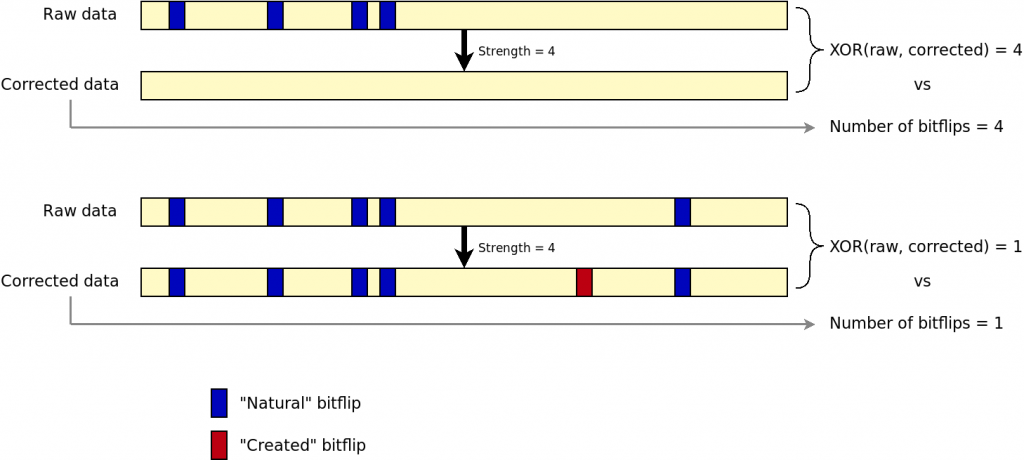
Use a bitwise XOR between raw and corrected data

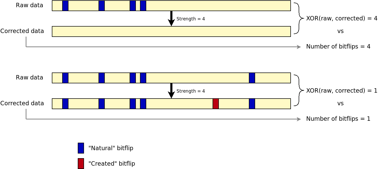
By doing a bitwise XOR between raw and corrected datra, and compare with the number of bitflips reported by the engine, we could detect if the engine is lying on the number of corrected bitflips. This solution has actually been implemented and tested. It involves extra I/Os as the page must be read twice: first with correction and then again without correction. Hence, the NAND bus throughput becomes a limiting factor. In addition, when there are too many bitflips, the engine still tries to correct data and creates bitflips by itself. The result is that, with just a XOR, we cannot discriminate a working correction from a failure. The following figure shows the issue.

Show the engine issue when it creates bitflips when trying to correct uncorrectable data

Rely on the hardware only in the write path

Using the hardware engine in the write path is fine (and possibly the quickest solution). Instead of trying to workaround the flaws of the read path, we can do the math by software to derive the syndrome in the read path and compare it with the one in the OOB section. If it does not match, it means we are facing an uncorrectable error. This is finally the solution that we have chosen. Of course, if we want to compare software and hardware calculated ECC bytes, we must find a way to reproduce the hardware calculations, and this is what we are going to explore in the next sections.

Reversing a hardware BCH ECC engine

There is already a BCH library in the Linux kernel on which we could rely on to compute BCH codes. What needed to be identified though, were the BCH initial parameters. In particular:

  • The BCH primary polynomial, from which is derived the generator polynomial. The latter is then used for the computation of BCH codes.
  • The range of data on which the derivation would apply.

There are several thousands possible primary polynomials with a form like x^3 + x^2 + 1. In order to represent these polynomials more easily by software, we use integers or binary arrays. In both cases, each bit represents the coefficient for the order of magnitude corresponding to its position. The above example could be represented by b1101 or 0xD.

For a given desired BCH code (ie. the ECC chunk size and hence its corresponding Gallois Field order), there is a limited range of possible primary polynomials which can be used. Given eccsize being the amount of data to protect, the Gallois Field order is the smallest integer m so that: 2^m > eccsize. Knowing m, one can check these tables to see examples of polynomials which could match (non exhaustive). The Arasan ECC engine supporting two possible ECC chunk sizes of 512 and 1024 bytes, we had to look at the tables for m = 13 and m = 14.

Given the required strength t, the number of needed parity bits p is: p = t x m.

The total amount of manipulated data (ECC chunk, parity bits, eventual padding) n, also called BCH codeword in papers, is: n = 2^m - 1.

Given the size of the codeword n and the number of parity bits p, it is then possible to derive the maximum message length k with: k = n - p.

The theory of BCH also shows that if (n, k) is a valid BCH code, then (n - x, k - x) will also be valid. In our situation this is very interesting. Indeed, we want to protect eccsize number of symbols, but we currently cover k within n. In other words we could use the translation factor x being: x = k - eccsize. If the ECC engine was also protecting some part of the OOB area, x should have been extended a little bit to match the extra range.

With all this theory in mind, we used GNU Octave to brute force the BCH polynomials used by the Arasan ECC engine with the following logic:

  • Write a NAND page with a eccsize-long ECC step full of zeros, and another one full of ones: this is our known set of inputs.
  • Extract each BCH code of p bits produced by the hardware: this is our known set of outputs.

For each possible primary polynomial with the Gallois Field order m, we derive a generator polynomial, use it to encode both input buffers thanks to a regular BCH derivation, and compare the output syndromes with the expected output buffers.

Because the GNU Octave program was not tricky to write, we first tried to match with the output of Linux software BCH engine. Linux using by default the primary polynomial which is the first in GNU Octave’s list for the desired field order, it was quite easy to verify the algorithm worked.

As unfortunate as it sounds, running this test with the hardware data did not gave any match. Looking more in depth, we realized that visually, there was something like a matching pattern between the output of the Arasan engine and the output of Linux software BCH engine. In fact, both syndromes where identical, the bits being swapped at byte level by the hardware. This observation was made possible because the input buffers have the same values no matter the bit ordering. By extension, we also figured that swapping the bits in the input buffer was also necessary.

The primary polynomial for an eccsize of 512 bytes being already found, we ran again the program with eccsize being 1024 bytes:

eccsize = 1024
eccstrength = 24
m = 14
n = 16383
p = 336
k = 16047
x = 7855
Trying primary polynomial #1: 0x402b
Trying primary polynomial #2: 0x4039
Trying primary polynomial #3: 0x4053
Trying primary polynomial #4: 0x405f
Trying primary polynomial #5: 0x407b
[...]
Trying primary polynomial #44: 0x43c9
Trying primary polynomial #45: 0x43eb
Trying primary polynomial #46: 0x43ed
Trying primary polynomial #47: 0x440b
Trying primary polynomial #48: 0x4443
Primary polynomial found! 0x4443

Final solution

With the two possible primary polynomials in hand, we could finish the support for this ECC engine.

At first, we tried a “mixed-mode” solution: read and correct the data with the hardware engine and then re-read the data in raw mode. Calculate the syndrome over the raw data, derive the number of roots of the syndrome which represents the number of bitflips and compare with the hardware engine’s output. As finding the syndrome’s roots location (ie. the bitflips offsets) is very time consuming for the machine it was decided not to do it in order to gain some time. This approach worked, but doing the I/Os twice was slowing down very much the read speed, much more than expected.

The final approach has been to actually get rid of any hardware computation in the read path, delegating all the work to Linux BCH logic, which indeed worked noticeably faster.

The overall work is now in the upstream Linux kernel:

If you’re interested about more details on ECC for flash devices, and their support in Linux, we will be giving a talk precisely on this topic at the upcoming Embedded Linux Conference!

Bootlin contributes Linux DRM driver for LogicBricks logiCVC-ML IP

LogicBricks is a vendor of numerous IP blocks, ranging from display controllers, audio controllers, 3D accelerators and many other specialized IP blocks. Most of these IP blocks are designed to work with the Xilinx Zynq 7000 system-on-chip, which includes an FPGA area. And indeed, because the Zynq 7000 does not have a display controller, one of Bootlin customers has selected the LogicBricks logiCVC-ML IP to provide display support for their Zynq 7000 design.

logiCVC-ML

LogiBricks provide one driver based on the framebuffer subsystem and another one based on the DRM subsystem, but none of these drivers are in the upstream Linux kernel. Bootlin engineer Paul Kocialkowski worked on a clean DRM driver for this IP block, and submitted the first version to the upstream Linux kernel. We already received some useful comments on the Device Tree binding for this IP block, which is pretty elaborate due to the number of aspects/features that can be tuned at IP synthesis time, and we will of course take into account those comments and send new iterations of the patch series until it gets merged.

In the e-mail containing the driver patch itself, Paul gives a summary of the IP features that are supported and tested, and those that re either untested or unsupported:

Introduces a driver for the LogiCVC display controller, a programmable
logic controller optimized for use in Xilinx Zynq-7000 SoCs and other
Xilinx FPGAs. The controller is mostly configured at logic synthesis
time so only a subset of configuration is left for the driver to
handle.

The following features are implemented and tested:
- LVDS 4-bit interface;
- RGB565 pixel formats;
- Multiple layers and hardware composition;
- Layer-wide alpha mode;

The following features are implemented but untested:
- Other RGB pixel formats;
- Layer framebuffer configuration for version 4;
- Lowest-layer used as background color;
- Per-pixel alpha mode.

The following features are not implemented:
- YUV pixel formats;
- DVI, LVDS 3-bit, ITU656 and camera link interfaces;
- External parallel input for layer;
- Color-keying;
- LUT-based alpha modes.

Additional implementation-specific notes:
- Panels are only enabled after the first page flip to avoid flashing a
  white screen.
- Depth used in context of the LogiCVC driver only counts color components
  to match the definition of the synthesis parameters.

Support is implemented for both version 3 and 4 of the controller.

With version 3, framebuffers are stored in a dedicated contiguous
memory area, with a base address hardcoded for each layer. This requires
using a dedicated CMA pool registered at the base address and tweaking a
few offset-related registers to try to use any buffer allocated from
the pool. This is done on a best-effort basis to have the hardware cope
with the DRM framebuffer allocation model and there is no guarantee
that each buffer allocated by GEM CMA can be used for any layer.
In particular, buffers allocated below the base address for a layer are
guaranteed not to be configurable for that layer. See the implementation of
logicvc_layer_buffer_find_setup for specifics.

Version 4 allows configuring each buffer address directly, which
guarantees that any buffer can be configured.

STM32MP1 system-on-chip, Bootlin member of ST Partners program

Earlier this year at Embedded World, STMicroelectronics announced the release of their first MPU, the STM32MP1 system-on-chip. Bootlin has been selected as one of the companies offering engineering and training services to be part of the ST Partners program around this new platform. In this blog post, we will give more details about STM32MP1 and Bootlin’s initial efforts on this platform.

The STM32MP1 platform

For the past several years, STMicroelectronics has developed a range of 32-bit microcontrollers based on the ARM Cortex-M cores. The most high-end ones, based on Cortex-M4 and M7, were powerful enough to run a Linux operating system with external RAM attached, and ST has been very active in adding support for these micro-controllers in the upstream U-Boot and Linux projects. However, the Cortex-M4 and M7 being MMU-less processor cores, Linux could work only with a number of limitations, preventing from using some complex Linux software stacks.

Block diagram of the STM32MP157
With the STM32MP1, ST is now offering a full-featured microprocessor, based on the combination of one or two Cortex-A7 cores (650 Mhz), one Cortex-M4 core (209 Mhz) and a wide variety of peripherals. The STM32MP1 is currently available in 3 variants:

  • STM32MP151, featuring one Cortex-A7, one Cortex-M4, and the common set of peripherals
  • STM32MP153, featuring two Cortex-A7, one Cortex-M4, the common set of peripherals plus CAN-FD
  • STM32MP157, featuring two Cortex-A7, one Cortex-M4, the common set of peripherals plus a 3D GPU, a DSI display interface and CAN-FD

The hardware blocks integrated in the STM32MP1 offers a large amount of features and connectivity options:

  • External DDR controller, supporting up to LPDDR2/3 and DDR3
  • QuadSPI memory interface
  • NAND flash controller, with built-in ECC capability
  • 6 I2C controllers
  • 4 UARTs and 4 USARTs
  • 6 SPI controllers
  • 4 SAI audio interfaces
  • HDMI-CEC interface
  • 3 SD/MMC controllers
  • 2 CAN controllers
  • 2 USB host + 1 USB OTG controllers
  • 1 Gigabit Ethernet MAC
  • Camera interface (parallel)
  • 2 ADCs, 2 DACs, 1 digital filter for sigma delta modulators
  • LCD controller supporting up to 1366×768
  • GPU from Vivante (which means open-source support is available!)
  • MIPI DSI
  • Plenty of timers
  • Crypto accelerators, random number generator (only in the C variants of the SoC)
  • Secure boot (only in the C variants of the SoC)

This combination of a wide range of connectivity options, graphics support with GPU support, and a Cortex-M4 for real-time logic, makes the STM32MP1 interesting for a large number of applications.

Software support for the STM32MP1

Bootlin being a consulting company specialized in low-level Linux software for embedded platforms, it is obviously a key aspect we looked at for the STM32MP1 platform.

First of all, a number of hardware blocks used in the STM32MP1 platform were already used on previous micro-controllers from ST and were therefore already supported in upstream projects such as U-Boot and Linux. The fact that these micro-controller products can run upstream versions of U-Boot and Linux is a good indication of ST’s strategy in terms of upstream support.

Then, even before the STM32MP1 product was publicly announced, a significant number of ST engineers had already started contributing to upstream TF-A, U-Boot and Linux the support for various pieces needed for the STM32MP1. Even if the support is not entirely upstream at this point, this strategy of starting the upstreaming effort ahead of the product announcement is very good.

Even though the work towards open-source GPU support has tremendously progressed over the past years, GPUs were notoriously known for being difficult to support in a fully open-source software stack. It is interesting to see that ST has chosen the GPU from Vivante for this STM32MP1, as Vivante is one of the first embedded GPU supported by Mesa, the open-source OpenGL implementation. Vivante GPUs are already used in a number of other SoCs, especially from NXP, and the Vivante open-source support, called etnaviv has therefore already seen some significant usage in production.

Until all the support for the STM32MP1 is fully upstreamed, ST provides publicly available Git repositories for all pieces of the software stack:

In addition to the availability of the code, there is also plenty of documentation available in the Development zone of the STM32 MPU wiki.

Hardware platforms for the STM32MP1

ST provides a low-cost evaluation platform called Discovery, available in two versions:

  • STM32MP157A-DK1, which features the STM32MP157A processor (all features, but without secure boot), LEDs, push buttons, Ethernet, one USB-C connector, 4 USB-A connectors, HDMI, microSD, analog audio, Arduino and RPi compatible connectors. The cost is $69.
  • STM32MP157C-DK2 features the STM32MP157C processor (all features including secure boot), and has the same features as the DK1 variant, with the addition of a DSI panel with touch and a WiFi/Bluetooth chip. The cost is $99.
STM32MP157-DK2 board

ST also provides some more feature-complete evaluation boards: the STM32MP157A-EV1 and STM32MP157C-EV1, which only differ by the lack or availability of secure boot support. They offer more hardware features than the Discovery platforms, and are obviously available at a higher cost, $399.

In addition to these platforms provided by ST, several manufacturers have already announced a number of boards or system-on-module based on the STM32MP1:

OSD32MP15x system-in-package

Bootlin member of ST’s partner program

Bootlin is proud to have been chosen by ST to be part of its partner program when the STM32MP1 platform was announced. As a software partner, Bootlin can offer its training and engineering services to customers using the STM32MP1. We can provide:

  • Engineering for the development of Linux Board Support Packages for STM32MP1 platforms: porting U-Boot, porting Linux, writing Linux device drivers, delivering a fully integrated and optimized Linux system generated with Yocto or Buildroot
  • Training on embedded Linux, Linux kernel development and Yocto usage around the STM32MP1 platform

Bootlin trainings on STM32MP1

As a ST partner, Bootlin will be porting two of its existing training courses to the STM32MP1 platform: this means that all the practical labs in those courses will take place on the STM23MP157 Discovery board. We will soon be announcing:

Of course, as Bootlin has always done, all the training materials will be made freely available, under the same Creative Commons license we already use for existing training materials.

Building a Linux system for STM32MP1

The STM32MP1 being the first micro-processor in this family of SoCs from ST, a number of companies will most likely migrate from a micro-controller environment to a micro-processor one. This means moving from a situation where only a bare-metal application or a simple RTOS is used, to a situation where a feature-rich operating system such as Linux is being used. This migration is not always trivial as it requires gaining a lot of knowledge about U-Boot, the Linux kernel, Linux system integration and development, and more.

In order to help with this, in addition to the training courses described above, we will soon start publishing a series of blog posts that describe step by step how to build a Linux system for the STM32MP157 Discovery Kit, all the way up to reading data from an I2C sensor, and displaying them in a Qt5 based application. Stay tuned on our blog for those articles in the next few weeks!

Power measurement with BayLibre’s ACME cape

When working on optimizing the power consumption of a board we need a way to measure its consumption. We recently bought an ACME from BayLibre to do that.

Overview of the ACME

The ACME is an extension board for the BeagleBone Black, providing multi-channel power and temperature measurements capabilities. The cape itself has eight probe connectors allowing to do multi-channel measurements. Probes for USB, Jack or HE10 can be bought separately depending on boards you want to monitor.

acme

Last but not least, the ACME is fully open source, from the hardware to the software.

First setup

Ready to use pre-built images are available and can be flashed on an SD card. There are two different images: one acting as a standalone device and one providing an IIO capture daemon. While the later can be used in automated farms, we chose the standalone image which provides user-space tools to control the probes and is more suited to power consumption development topics.

The standalone image userspace can also be built manually using Buildroot, a provided custom configuration and custom init scripts. The kernel should be built using a custom configuration and the device tree needs to be patched.

Using the ACME

To control the probes and get measured values the Sigrok software is used. There is currently no support to send data over the network. Because of this limitation we need to access the BeagleBone Black shell through SSH and run our commands there.

We can display information about the detected probe, by running:

# sigrok-cli --show --driver=baylibre-acme
Driver functions:
    Continuous sampling
    Sample limit
    Time limit
    Sample rate
baylibre-acme - BayLibre ACME with 3 channels: P1_ENRG_PWR P1_ENRG_CURR P1_ENRG_VOL
Channel groups:
    Probe_1: channels P1_ENRG_PWR P1_ENRG_CURR P1_ENRG_VOL
Supported configuration options across all channel groups:
    continuous: 
    limit_samples: 0 (current)
    limit_time: 0 (current)
    samplerate (1 Hz - 500 Hz in steps of 1 Hz)

The driver has four parameters (continuous sampling, sample limit, time limit and sample rate) and has one probe attached with three channels (PWR, CURR and VOL). The acquisition parameters help configuring data acquisition by giving sampling limits or rates. The rates are given in Hertz, and should be within the 1 and 500Hz range when using an ACME.

For example, to sample at 20Hz and display the power consumption measured by our probe P1:

# sigrok-cli --driver=baylibre-acme --channels=P1_ENRG_PWR \
      --continuous --config samplerate=20
FRAME-BEGIN
P1_ENRG_PWR: 1.000000 W
FRAME-END
FRAME-BEGIN
P1_ENRG_PWR: 1.210000 W
FRAME-END
FRAME-BEGIN
P1_ENRG_PWR: 1.210000 W
FRAME-END

Of course there are many more options as shown in the Sigrok CLI manual.

Beta image

A new image is being developed and will change the way to use the ACME. As it’s already available in beta we tested it (and didn’t come back to the stable image). This new version aims to only use IIO to provide the probes data, instead of having a custom Sigrok driver. The main advantage is many software are IIO aware, or will be, as it’s the standard way to use this kind of sensors with the Linux kernel. Last but not least, IIO provides ways to communicate over the network.

A new webpage is available to find information on how to use the beta image, on https://baylibre-acme.github.io. This image isn’t compatible with the current stable one, which we previously described.

The first nice thing to notice when using the beta image is the Bonjour support which helps us communicating with the board in an effortless way:

$ ping baylibre-acme.local

A new tool, acme-cli, is provided to control the probes to switch them on or off given the needs. To switch on or off the first probe:

$ ./acme-cli switch_on 1
$ ./acme-cli switch_off 1

We do not need any additional custom software to use the board, as the sensors data is available using the IIO interface. This means we should be able to use any IIO aware tool to gather the power consumption values:

  • Sigrok, on the laptop/machine this time as IIO is able to communicate over the network;
  • libiio/examples, which provides the iio-monitor tool;
  • iio-capture, which is a fork of iio-readdev designed by BayLibre for an integration into LAVA (automated tests);
  • and many more..

Conclusion

We didn’t use all the possibilities offered by the ACME cape yet but so far it helped us a lot when working on power consumption related topics. The ACME cape is simple to use and comes with a working pre-built image. The beta image offers the IIO support which improved the usability of the device, and even though it’s in a beta version we would recommend to use it.

A Kickstarter for a low cost Marvell ARM64 board

At the beginning of October a Kickstarter campaign was launched to fund the development of a low-cost board based on one of the latest Marvell ARM 64-bit SoC: the Armada 3700. While being under $50, the board would allow using most of the Armada 3700 features:

  • Gigabit Ethernet
  • SATA
  • USB 3.0
  • miniPCIe

ESPRESSObin interfaces

The Kickstarter campaign was started by Globalscale Technologies, who has already produced numerous Marvell boards in the past: the Armada 370 based Mirabox, the Kirkwood based SheevaPlug, DreamPlug and more.

We pushed the initial support of this SoC to the mainline Linux kernel 6 months ago, and it landed in Linux 4.6. There are still a number of hardware features that are not yet supported in the mainline kernel, but we are actively working on it. As an example, support for the PCIe controller was merged in Linux 4.8, released last Sunday. According to the Kickstarter page the first boards would be delivered in January 2017 and by this time we hope to have managed to push more support for this SoC to the mainline Linux kernel.

We have been working on the mainline support of the Marvell SoC for 4 years and we are glad to see at last the first board under $50 using this SoC. We hope it will help expanding the open source community around this SoC family and will bring more contributions to the Marvell EBU SoCs.

Embedded Linux training update: Atmel Xplained, and more!

Atmel SAMA5D3 Xplained boardWe are happy to announce that we have published a significant update of our Embedded Linux training course. As all our training materials, this update is freely available for everyone, under a Creative Commons (CC-BY-SA) license.

This update brings the following major improvements to the training session:

  • The hardware platform used for all the practical labs is the Atmel SAMA5D3 Xplained platform, a popular platform that features the ARMv7 compatible Atmel SAMA5D3 processor on a board with expansion headers compatible with Arduino shields. The fact that the platform is very well supported by the mainline Linux kernel, and the easy access to a wide range of Arduino shields makes it a very useful prototyping platform for many projects. Of course, as usual, participants to our public training sessions keep their board after the end of the course! Note we continue to support the IGEPv2 board from ISEE for customers who prefer this option.
  • The practical labs that consist in Cross-compiling third party libraries and applications and Working with Buildroot now use a USB audio device connected to the Xplained board on the hardware side, and various audio libraries/applications on the software side. This replaces our previous labs which were using DirectFB as an example of a graphical library used in a system emulated under QEMU. We indeed believe that practical labs on real hardware are much more interesting and exciting.
  • Many updates were made to various software components used in the training session: the toolchain components were all updated and we now use a hard float toolchain, more recent U-Boot and Linux kernel versions are used, etc.

The training materials are available as pre-compiled PDF (slides, labs, agenda), but their source code in also available in our Git repository.

If you are interested in this training session, see the dates of our public training sessions, or order one to be held at your location. Do not hesitate to contact us at training@bootlin.com for further details!

It is worth mentioning that for the purpose of the development of this training session, we did a few contributions to open-source projects:

Thanks a lot to our engineers Maxime Ripard and Alexandre Belloni, who worked on this major update of our training session.

ISEE working on IGEPv5 board with OMAP5

Our partner ISEE is famous for their IGEPv2 board that we use in our embedded Linux course. This board is both powerful (running at 1 GHz) and featureful (on-board WiFi and Bluetooth, many connectors and expansion capabilities).

The good news is that ISEE has started to develop a new IGEPv5 board, which will be based on the new OMAP5 processor from Texas Instruments. This processor features in particular 2 ARM Cortex A15 cores running at up to 2 GHz, DDR3 RAM support, USB3, full HD 3D recording, and supporting 4 displays and cameras at the same time. Can you imagine what systems you could create with such a CPU?

If you are interested in such a board, it is still time for you to give them your inputs and expectations.

What should a perfect OMAP5 board be like? Don’t hesitate to leave your comments on this blog post. Be sure that ISEE will pay attention to them.

Embedded Linux practical labs with the Beagle Board

Note: the materials for training with the Beagle Board are no longer available, and would be significantly out of date anyway. We advise you to check our Embedded Linux System Development and Linux Kernel and Driver Development training courses for up-to-date instructions that work on cheaper boards, which are still available on the market today. And if you still have an old Beagle board, it will be an interesting exercise to adapt our current labs to run them on such hardware.

We were asked to customize our embedded Linux training session with specific labs on OMAP 3530 hardware. After a successful delivery on the customer site, using Beagle boards, here are our training materials, released as usual under the terms of the Creative Commons Attribution-ShareAlike 3.0 license:

If you are the happy owner of such a board (both attractive and cheap), or are interested in getting one, you can get valuable embedded Linux experience by reading our lecture materials and by taking our practical labs.

Here’s what you would practise with if you decide to take our labs:

  • Build a cross-compiling toolchain with crosstool-NG
  • Compile U-boot and the X-loader and install it on MMC and flash storage.
  • Manipulate Linux kernel sources and apply source patches
  • Configure, compile and boot a Linux kernel for an emulated PC target
  • Configure, cross-compile and boot a Linux kernel on your Beagle Board
  • Build a tiny filesystem from scratch, based on BusyBox, and with a web server interface. Practice with NFS booting.
  • Put your filesystem on MMC storage, replacing NFS. Practice with SquashFS.
  • Put your filesystem on internal NAND flash storage. Practice with JFFS2 too.
  • Manually cross-compile libraries (zlib, libpng, libjpeg, FreeType and DirectFB) and a DirectFB examples, getting familiar with the tricks required to cross-compile components provided by the community.
  • Build the same kind of graphical system automatically with Buildroot.
  • Compile your own application against existing libraries. Debug a target application with strace, ltrace and gdbserver running on the target.
  • Do experiments with the rt-preempt patches. Measure scheduling latency improvements.
  • Implement hotplugging with mdev, BusyBox’s lightweight alternative to udev.

Note that the labs were tested with Rev. C boards, but are also supposed to work fine with Rev. B ones. You may also be able to reuse some of our instructions with other boards with a TI OMAP3 processor.

Of course, if you like the materials, you can also ask your company to order such a training session from us. We will be delighted to come to your place and spend time with you and your colleagues.

CALAO boards supported in mainline U-Boot

I’m happy to announce that a couple days ago, support for the CALAO SBC35-A9G20, TNY-A9260 and TNY-A9G20 boards made its way into the U-Boot git repository. Sadly, it’s not possible to boot from an MMC/SD card with the SBC35 yet, but it’s something I’m currently working on.

Support for all these cards will be available in the next U-Boot release, due in November.