The entire team at Bootlin is extremely happy to welcome Luca Ceresoli, who started working with us on March 1, 2022. Based in Italy, Luca is the first employee of Bootlin based outside of France, and we plan to continue to expand our hiring in a similar way in the future.
Luca brings a vast amount of embedded and embedded Linux expertise to the Bootlin team. Luca has been working on embedded products since 2002, and embedded Linux products since 2008. He has helped design, develop and ship products based on a large number of embedded processors, developing complete BSPs, developing Linux kernel drivers, integrating complete systems using Buildroot or Yocto. Luca has also contributed to the Linux kernel, Buildroot, and several open-source projects, and has spoken several times at FOSDEM, the Embedded Linux Conference, and other events.
Luca’s arrival at Bootlin not only means that we have more capacity to help our customers with their embedded Linux projects, but also that we have more capacity to deliver training courses, and a new ability to deliver some of our training courses in Italian.
Last year, Bootlin started contributing to the OP-TEE project, which is an open source Trusted Execution Environment (TEE) implemented using the Arm TrustZone technology. We published a blog post about our contribution of a generic clock framework to OP-TEE, and also presented a talk OP-TEE: When Linux Loses Control (slides, video).
As part of this work, Bootlin engineer Clément Léger contributed to the OP-TEE project, and many of his contributions have already been merged, and released as part of the 3.15 and 3.16 OP-TEE releases. In this blog post, we present some details of our contributions to OP-TEE so far, and our next steps.
Summary
Since then, we contributed a number of features and improvements to OP-TEE. First, a number of generic, HW-agnostic contributions:
We contributed 48 commits to OP-TEE 3.16.0. This level of contribution makes Bootlin engineer Clément Léger the second most active contributor by number of commits for this OP-TEE release.
We will continue our effort on sam5d2 support on OP-TEE and as part of this, there will be contributions on several generic subsystems as well as SAMA5D2 support:
Watchdog support
Generic watchdog API
OP-TEE Watchdog service compatible with arm,smc-wdt Linux driver
Sama5d2 watchdog driver
RTC support
Generic RTC API
OP-TEE RTC PTA to expose RTC to Linux
sama5d2 RTC driver
Linux driver for OP-TEE RTC
SAMA5D2 suspend support
Support forULP0, ULP1, ULP0 Fast and backup modes
PSCI support
SAMA5D2 interrupt controller support
Do not hesitate to contact us if you need help and support to integrate or deploy OP-TEE on your platform, either Microchip platforms, but also other ARM32 or ARM64 platforms.
The Device Tree language is a way to describe hardware that is present in a system and cannot be automatically detected. That’s the case of devices directly implemented on a System on a Chip, such as serial ports, Ethernet or Nand flash controllers. That’s also the case of devices connected to a number of buses, such as I2C and SPI, that do not provide mechanisms for dynamic enumeration and identification of devices.
For a given CPU architecture (ARM, PowerPC, etc), such a description allows to have a unique kernel supporting many different systems with distinct Systems on a Chip. The compiled Device Tree (DTB: Device Tree Binary), passed to the kernel by the bootloader at boot time, lets the kernel know which SoC and devices to initialize. Therefore, when you create a new board, and want to use a standard GNU/Linux distribution on it, all you have to do is create a new Device Tree describing your new hardware, compile it, and boot the distribution’s kernel with it. You don’t need to recompile that kernel, at least when it supports your SoC and the devices on your board.
Kernel developers and board maintainers are not the only ones who may need to make changes to the board device trees, though. Normal users also have legitimate reasons for tweaking the device tree of their board, such as:
Declaring external devices connected to board connectors. The simplest example is an I2C temperature sensor, but this can also include entire expansion boards plugged into the main board.
Changing the hardware blocks that are exposed on the external pins of their System on Chip. This is called Pin Multiplexing, and the Device Tree is the place where such multiplexing is configured.
Modifying operating system related properties, such as the Linux kernel command line or flash partitions.
In you have such a need, a first way to do this would be to directly modify the Device Tree for your hardware in the kernel sources, and recompile it. However, this is a rather bad idea because it will make it more difficult to upgrade to a later version of the kernel, possibly featuring changes to the Device Tree file you modified too. It’s always better not to tweak files maintained by others, and find a way to override them instead.
A second possibility to tweak the Device Tree for a board is to include it from a custom Device Tree for your own use case, using the /include/ statement from the Device Tree language, or #include and the C preprocessor. You can then use references to nodes in the original tree, using labels, and then modify the properties of such nodes or add new subnodes to them. It’s even possible to remove existing nodes and properties by using the /delete-node/ and /delete-property/ statements, as shown in the Device Tree Source Undocumented page.
However, this is still an inconvenient solution. Any time you plug in a new device or an expansion board, or want to tweak other settings, you have to rebuild and update the full Device Tree for your board. What if you could prepare Device Tree fragments for each change to make, compile them once for all, and then, when you boot your device, load the main Device Tree and only the fragments you need, without having anything else to recompile?
This is exactly what Device Tree Overlays are about. For example, in /lib/firmware, the Debian image shipped by BeagleBoard.org contains compiled Device Tree Overlays (DTBO) for the extension boards (also known as capes in the BeagleBoard world) they support, such as:
Then, at boot time, all you have to do is load the main DTB for your board, and then override it using the DTBOs corresponding to the capes which are currently mounted. Kernel contributors have also worked on solutions to load the DTBOs dynamically in the live system, but this solution is not mature yet. Therefore, the bootloader based solution at boot time remains so far the best one.
Writing Device Tree overlays
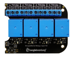
When the Device Tree overlays were first proposed, their syntax was very special and hard to remember. Fortunately, since version 1.5, the Device Tree compiler (dtc) supports a much more natural syntax for writing such overlays. For example, here are the sources for the overlay for the Relay cape, taken from the BBORG_RELAY-00A2.dts file in BeagleBoard.org’s Linux kernel tree:
BeagleBone Relay Cape
This example shows us what is specific to Device Tree Overlay source code, compared to the normal Device Tree syntax:
Before any definition, the code must include the /plugin/; statement.
As in normal Device Tree code, you can refer to labels (such as &am33xx_pinmux in the above example), modify their properties, add or remove nodes and properties.
However, you cannot modify nodes which do not have a label. In this case, you have to recall such nodes by describing their absolute path from the root device between curly braces. There are two such instances in the above code: &{/chosen} and &{/}.
Compiling Device Tree overlays
Once you have the source code of the your overlay, it is supposed to be easy to compile it with the Device Tree Compiler. This time, let’s take the example of the BBORG_FAN-A000.dts overlay for the Fan cape, slightly modified:
The only change we made to this file was to replace __TIMESTAMP__ by a real timestamp. This statement is actually a macro meant to be substituted by the C Preprocesor before compiling with dtc.
This is where real life Device Tree overlay examples are getting more difficult to compile. Very simple overlays can be compiled with the above command, but as soon as the code contains #include statements or macros to be substituted by the C preprocessor, you have to call this preprocessor and give it the path to where the corresponding .h files are found in the kernel sources.
Fortunately, the kernel Makefile knows a suitable series of commands to compile such overlay sources.
Let’s clone BeagleBoard.org’s Linux kernel source tree. It contains Device Tree Overlays for most capes that are compatible with BeagleBoarg.org’s boards, and if I understood correctly, BeagleBoard.org’s kernel developers haven’t solved all the conflicts between their definitions and recent kernels yet. So, let’s checkout their 5.10 branch:
git clone https://github.com/beagleboard/linux.git
cd linux
git branch -a
git checkout 5.10
First, let’s install a toolchain, for example the one on Ubuntu:
sudo apt install gcc-arm-linux-gnueabihf
And then let’s prepare the environment for compiling the kernel:
Then, we can configure the kernel for the OMAP SoCs:
make omap2plus_defconfig
We also need to tweak the configuration for compiling the Device Trees and Overlays properly. So, run make menuconfig and set CONFIG_OF_OVERLAY=y. For the practical manipulations, you will also need to set CONFIG_LEDS_GPIO=y and CONFIG_LEDS_CLASS=y.
Device Tree Overlays are found in arch/arm/boot/dts/overlays/. You can compile them along with all normal DTBs with:
make dtbs
In case you want to recompile a specific DT overlay, for example the BBORG_RELAY-00A2.dts file:
$ touch arch/arm/boot/dts/overlays/BBORG_RELAY-00A2.dts
$ make dtbs
  DTCO    arch/arm/boot/dts/overlays/BBORG_RELAY-00A2.dtbo
Of course, for any of this to be useful at the end, you will also need to compile the kernel:
make -j8 zImage
Applying Device Tree overlays
As we already explained, U-Boot is the place where the Device Tree Overlays should be applied. To do this, here are the commands to run in U-Boot. As an example, we’re using the BeagleBone Black and its Relay Cape as example, assuming all the files where copied to the first partition of a micro-SD card, containing a FAT filesystem:
Allocate extra space for the DTB for future overlays, here adding 8192 bytes for example:
fdt resize 8192
Apply the overlay that we just loaded to the main DTB:
fdt apply 0x83000000
We are then ready to load the Linux kernel and boot it. Let’s see a more complete example…
Example usage on BeagleBone Black
You can of course follow this example, but you can also test it by yourself if you own the BeagleBone Black (or similar BeagleBone boards), and its Relay Cape.
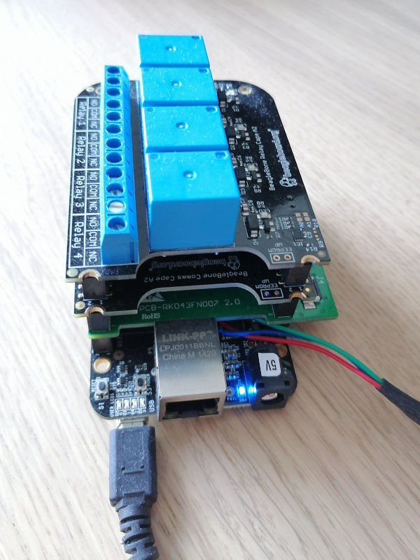
Board setup
First, connect the Relay Cape to your board. In the below example, more capes are actually stacked, the Relay Cape being on top, as its volume doesn’t allow for further capes:
Then, take a microSD card and format its first partition with the FAT32 filesystem:
sudo mkfs.vfat -F 32 -n boot /dev/mmcblk0p1
Remove the microSD card and insert it again. It should now be mounted on /media/$USER/boot. Download an archive containing all the files you should need for the BeagleBone Black and its Relay Cape, and extract this archive in this mount point.
This archive contains U-Boot binaries for the BeagleBone Black, a DTB for the same board, Device Tree Overlays for BeagleBone capes under the overlays/ directory, and a kernel including its own root filesystem as an initramfs. This way, you don’t have to prepare another partition to hold the root filesystem. Note that the src/ subdirectory contains the Buildroot 2021.02 configuration to generate the root filesystem, as well as the Linux kernel configuration that we used.
To boot on U-Boot on the microSD card, press the USER button next to the USB host connector, when you power-up the board. Note that this is needed only once, until the board is completely switched off again. The board will continue to boot from the microSD card across reboots and resets. Make sure that the U-Boot prompt shows a 2021.07 U-Boot version.
Once in U-Boot, you can load the kernel, DTB and DTBO, apply the overlay as shown in the previous session:
You are now ready to boot your kernel with its updated Device Tree:
bootz 0x81000000 - 0x82000000
Then, log in with the root user and an empty password.
Checking from Linux that the overlay was applied
The first thing you can check is that the device tree overlay was indeed applied. You can do this by checking properties which are specific to the overlay, such as the one that was added to the chosen node (see the BBORG_RELAY-00A2.dts sources once again.
$ cd /proc/device-tree/chosen/overlays/
$ ls
BBORG_RELAY-00A2.kernel  name
Our overlay specific property is there, but in a more general case, look for properties under /proc/device-tree which are specific to each overlay.
Testing the Relay cape
Have a look again at BBORG_RELAY-00A2.dts file. In particular, for each relay, it declares an LED which is controlled by the same GPIO:
Each LED is given a label that will correspond to a directory under /sys/class/leds:
# ls /sys/class/leds/relay-*
/sys/class/leds/relay-jp1:
brightness      max_brightness  subsystem       uevent
device          power           trigger

/sys/class/leds/relay-jp2:
brightness      max_brightness  subsystem       uevent
device          power           trigger

/sys/class/leds/relay-jp3:
brightness      max_brightness  subsystem       uevent
device          power           trigger

/sys/class/leds/relay-jp4:
brightness      max_brightness  subsystem       uevent
device          power           trigger
Since the each LED and associated relay are controlled by the same GPIO, this gives us a convenient interface to control the each relay. We just have to control the corresponding LED by using its interface in /sys/class/leds.
This may not be a generic solution to control relays, but it will be easier than having to use the libgpiod library and its associated tools.
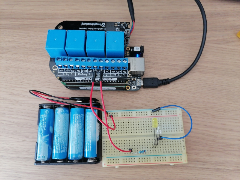
Testing a relay for real
Now, let’s try to control Relay 3.
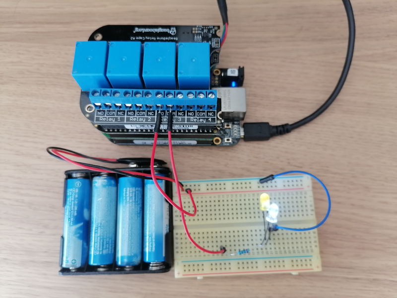
You are ready to connect a real circuit now. When the relay is inactive, the COM (Common) and NO (Normally Open) ports should be disconnected, while COM and NC (Normally Connected) should be connected. When you write 1 to the GPIO, the relay should then connect COM and NO:
The high voltage and low voltage parts of a relay are supposed to be separate and insulated, but in case their was a defect on my cape, I made my tests with a simple low-voltage circuit. However, relays are meant to be used for controlling normal AC voltages (110V / 230V).
Initial state – Relay off
Now, turn on Relay 3 by setting a non zero brightness on the corresponding LED:
echo 1 > /sys/class/leds/relay-jp3/brightness
Relay on, after echo 1 > /sys/class/leds/relay-jp3/brightness
You can turn the relay back off as follows:
echo 0 > /sys/class/leds/relay-jp3/brightness
Don’t hesitate to use this cape in your home automation projects!
What to remember
Device Tree Overlays are Device Tree fragments used to customize the Device Tree of a given board, typically to describe components added externally, including entire expansion boards, or tweak pin multiplexing. That’s the mechanism used by BeagleBoard.org’s kernel developers to support the numerous expansion boards (also known as capes) compatible with their boards. All you have to do is load the main Device Tree Binary for a board (DTB), and then load and apply Device Tree Overlay Binaries (DTBO).
Bootlin thanks BeagleBoard.org for funding the creation of this blog post. Note that more posts are coming in the next weeks, one about the BeagleBone Cape Interface Specification and one about the extension board manager we added to U-Boot.
Since the start of the pandemic in March 2020, we have been offering our popular training courses online to our customers, in both public sessions (opened to individual registration) and dedicated sessions (organized on-demand for our customers, at their choice of date/time).
Our public sessions were initially all organized in the afternoon of Europe (14:00 to 18:00 Paris time), but we started in late 2021 proposing our Embedded
Linux system development training course for customers in the US/America, especially on the West Coast. Thanks to the success of this, we have decided to also start offering at times convenient for US/America customers the following courses:
our Linux kernel driver development training course. The first session is scheduled from April 11 to April 21, with Bootlin engineer and trainer Miquèl Raynal, who is also a maintainer in the Linux kernel! The course runs from 09:00 AM to 1:00 PM Pacific, 12:00 PM to 4:00 PM Eastern, 6:00 PM to 10:00 PM Europe. Registration at the discount rate until March 10 for 829 EUR.
our Yocto/OpenEmbedded system development training course. The first session is scheduled from March 7 to March 10, with Bootlin engineer and trainer Maxime Chevallier. The course runs from 09:00 AM to 1:00 PM Pacific, 12:00 PM to 4:00 PM Eastern, 6:00 PM to 10:00 PM Europe. Registration at the discount rate is available until February 6 for 519 EUR.
The chosen time is ideal for US/America customers, but also works for participants in Europe who would like to attend our courses outside of their normal working hours.
Of course, we have plenty of other training sessions scheduled, for all our 7 different training courses, covering a wide range of time zones. Check our training page for all the details, and contact us if you have specific needs: a dedicated training course for your company, a session organized at a different date/time, etc.
Linux 5.16 has been released on January 9. As usual, our recommended reading to learn more about this release is the corresponding Kernelnewbies.org page and the two articles from LWN covering the 5.16 merge window: part 1 and part 2.
As usual, Bootlin contributed a number of patches to this release, with a total of 117 commits, making Bootlin the 22th contributing company according to statistics (Unknown and Hobbyists not counting as companies).
Here are the main highlights of our contributions to 5.16:
Alexandre Belloni, as the maintainer of the RTC subsystem, continued to improve the core subsystem and RTC drivers. He added a new user-space interface to RTC to allow getting/settings RTC parameters. It is used to get the features of an RTC from user-space, to get/set the RTC correction or to configure Backup Switch Mode. In addition, Alexandre made various improvements to several RTC drivers, such as adding Backup Switch Mode, and general refactoring.
Clément Léger did a small fix in the clock drivers for Microchip ARM platforms, fixing an issue discovered as part of his work porting OP-TEE to Microchip ARM platforms.
Hervé Codina made some fixes to the fsmc NAND controller driver, which is used on a number of old platforms from ST. They fix support of certain NAND chips on those platforms. These issues were discovered as part of the development of a Linux BSP for an old ST Spear320 platform.
Maxime Chevallier fixed a deadlock in the network stack, that was causing the kernel to stop booting when using a root filesystem over NFS combined with the network interface using a SFP module.
Miquèl Raynal contributed many improvements to the max1027 ADC driver in the IIO subsystem, supporting hardware triggers.
Miquèl Raynal contributed support for the ADC found on Texas Instruments AM437x platforms. This required significant changes in the MFD driver that is used to support the multiple features of this ADC, as well as improvements in the existing IIO driver for TI ADCs.
Paul Kocialkowski contributed a small addition enabling the Rockchip VPU on Rockchip PX30 platforms, and merged the Device Tree bindings for the logiCVC display controller (but not yet the driver itself).
2021 has come to an end, a year that everyone will most likely consider as somewhat complicated and unusual, even though the current situation seems to now becoming the new normal. The switch to a new year is generally a good moment to take a step back, and review what happened in the past year, and draw some directions for the coming year.
In this blog post, we’d like to do exactly this for Bootlin, which has seen a number of significant changes this year, as well as a continuation of its usual activities.
We also take this opportunity to wish you all an happy year 2022, and send you our best wishes. May 2022 be full of interesting projects and also be a safe year for everyone.
Here are the main topics that we cover in this lengthy blog post:
One major change for Bootlin in 2021 is that the company was acquired by Thomas Petazzoni, former CTO, and Alexandre Belloni. So it’s an internal acquisition, by former employees, meaning that Bootlin has kept the same offering and spirit. Further, Bootlin’s original founder Michael Opdenacker is still in the team, but now as an employee. See our blog post regarding the acquisition, back in February.
In 2021, we also recruited several engineers, bringing significant additional expertise to our team:
Thomas Perrot, who joined just before the start of 2021, bringing 10 years of experience in embedded Linux BSP development, with a strong Yocto expertise.
Hervé Codina, who joined in March 2021, bringing 20+ years of experience in bare-metal and Linux embedded development.
Clément Léger who joined in June 2021, bringing 10 years of experience in Linux kernel development, including the expertise on porting the Linux kernel to a brand new CPU architecture.
We continue to have open positions for embedded Linux engineers, and we plan to hire 3 to 4 engineers in 2022, hiring for the first time engineers located outside of France.
Engineering projects
As is the case every year, our engineering team has been kept busy this year mostly by our engineering projects, all focused on our core expertise of low-level embedded Linux development.
We have selected below a few highlights of our work in 2021, in various areas.
Build systems
Apart from delivering numerous BSPs based on Yocto or Buildroot to our customers, we have also directly contributed to both the Yocto and Buildroot open-source projects.
On the Yocto Project side:
Bootlin engineer Michael Opdenacker has become one of the co-maintainers of the official Yocto Project documentation, making numerous improvements and contributions to this documentation. See our blog post on this topic. We will continue this involvement in the Yocto Project documentation in 2022.
Bootlin engineer and COO Alexandre Belloni has been active in the build and release engineering effort of the Yocto Project, as a member of the Yocto Project SWAT team. Alexandre has been working directly with the main Yocto Project architect, Richard Purdie, on the review and validation of new contributions. Other Bootlin engineers have also helped in investigating and resolving specific bugs. We will also continue this involvement in the Yocto Project build engineering in 2022.
On the Buildroot side:
We have continued our work towards the implementation of top-level parallel build support in Buildroot. Bootlin engineer Hervé Codina has posted several iterations of a patch series bringing a mechanism preventing file overwrites between packages, a requirement for proper top-level parallel build.
We implemented and published, in partnership with ST, a Buildroot BR2_EXTERNAL called buildroot-external-st which contains example configurations for the STM32MP1 platforms from ST.
We contributed support for hybrid ISO9660 images, supporting in a single image PC platforms based on legacy BIOS, 32-bit UEFI BIOS and 64-bit UEFI BIOS, using the grub2 bootloader.
We helped one of our customers reduce their out-of-tree Buildroot patches by upstreaming a number of new Buildroot packages.
Outside of our the Yocto Project and Buildroot, we also ventured into the world of Debian/Ubuntu for embedded systems, by using the ELBE tool, to which we contributed support for building Ubuntu-based images. See our blog post that describes how to use ELBE to automatically build Ubuntu-based images for the Raspberry Pi.
Audio support in Linux
Audio support in the Linux kernel is another area where Bootlin engineers have specific expertise with. Here are some examples of audio related projects we worked on in 2021:
Integration of audio support for an i.MX6 platform with a complex dual AD1978 audio codec configuration, with a TDM8 audio interface between the SoC and the audio codecs.
Development of a brand new and complete ALSA driver for a new PCIe sound card, based on a FPGA.
Integration of audio support for an i.MX8 platform used in the automotive space with a complex audio configuration that involves multiple A2B transceivers through the Analog Devices AD2428 A2B master, Bluetooth audio, and more.
OP-TEE
In 2021, we started working on a major project: adding support for the Microchip SAMA5D2 processor to the OP-TEE project. This project is already well underway, as we have a functional port of OP-TEE, which is now being upstreamed.
As part of this, Bootlin engineer Clément Léger has implemented and contributed a generic clock framework for OP-TEE, which has already been accepted upstream. See our blog post for more details.
Clément also gave a talk at the Embedded Linux Conference 2021 on the topic of OP-TEE, titled OP-TEE: When Linux Loses Control. Slides and video are available.
We expect to continue the upstreaming of the SAMA5D2 support in 2022, and also develop support for additional SAM5D2 hardware capabilities in OP-TEE.
U-Boot extension board manager
In collaboration with the BeagleBoard.org community, we developed and contributed to U-Boot a generic extension board manager. This mechanism allows hardware platforms such as the BeagleBone to automatically detect extension boards that are connected, and apply the Device Tree overlays that provide the hardware description for those extension boards.
This work was covered in detail in the talk given by Bootlin engineer Köry Maincent at the Live Embedded Event in June 2021, see the slides and video.
Modems
In 2021, we had the opportunity to work on several projects that involved 3G/4G/5G modems, strengthening our knowledge of the modem stack in Linux, especially around modem-manager, libmbim and libqmi.
For example, we worked on the support of a Quectel BG95 modem interfaced with a RaspberryPi 4, or the support of a Sierra Wireless EM9190 modem interfaced over PCIe to an NXP i.MX6. The latter was particularly challenging and is still on-going, as the upstream Linux support for PCIe 5G modems is still very recent. We contributed a few fixes in this area.
Secure boot
Secure boot remains an important topic for a growing number of projects, and in 2021, we helped customers with secure boot on several i.MX6 platforms, and on one i.MX8 platform. The Yocto integration of secure boot was also a key aspects in those projects, to get a proper process for signing and verifying all states of the boot process. We also have a few U-Boot contributions in our contribution pipeline related to improving secure boot support. See for example the talk from Thomas Perrot at Live Embedded Event, relating the secure boot setup on i.MX8.
Camera, ISP and video support
We finished 2020 with a lot of on-going contributions to the Linux Video4Linux subsystem, which we had summarized in a blog post early 2021. In particular, our drivers for the OV5568 and OV8865 camera sensors were merged upstream.
In 2021, Bootlin engineer and multimedia expert Paul Kocialkowski continued to work on several multimedia topics. Some of the key projects included:
Optimizing the H264 decode → rescale → H264 encode pipeline of one of our customers, on an Allwinner H3 platform. We were able to significantly optimize the pipeline by leveraging the H264 decoder built into the Allwinner processor, for which Paul had written a Linux kernel driver several years ago, and by developing a custom ffmpeg plugin that offloaded the rescaling to the GPU, using the open-source lima support. A fully open-source solution!
Developing a proper Linux kernel driver for the Allwinner ISP, with support for debayering and noise filtering. This was a significant challenge as the Allwinner ISP was so far only supported through closed-source binary blobs. We have already submitted a first iteration to the upstream Linux kernel community. See our blog post for more details, as well as the talk given by Paul at the Embedded Linux Conference: slides and video.
Improving the Allwinner Linux kernel camera driver to support single buffer capture. This is useful in scenarios where camera sensors are not used to capture a sequence of frames, but just single frames, and the available memory is limited. This is particularly true on platforms such as the Allwinner V3s, which may be limited to just 64MB of RAM. This is going to be submitted upstream soon, as part of our on-going work on the Allwinner camera driver.
NAND and flash support
With Bootlin engineer Miquèl Raynal being a maintainer of the NAND subsystem in Linux and a co-maintainer of the MTD subsystem, it should be no surprise that we have continued to deal with a number of flash memory related projects in 2021:
We have brought in mainline the support for several NAND flash controllers:
For the Arasan NAND controller, used in some Xilinx processors. See our blog post on this topic.
For the ARM Primecell PL35x NAND controller, used in some other Xilinx processors. See our blog post on this topic.
For the NAND controller found at least in the the Renesas R-Car Gen3 and RZ/N1 processors.
Contributed support for the NV-DDR interface, which is used by some NAND flash chips and controllers to increase the throughput. See our blog post.
Continued our work on generalizing ECC support in the MTD subsystem, so that all ECC setups (software ECC, on-die ECC, ECC in the NAND controller, or external ECC engine) can be supported regardless of the NAND interface (serial or parallel). See the talk from Miquèl Raynal, ECC engines given at last year’s ELCE.
Improved the TI GPMC NAND controller driver to properly support NAND chip with large pages (larger than 4KB).
ADC/IIO support
We’ve helped a few customers with Linux kernel support for ADC devices, namely:
Extend the support for the MAX1027 family of ADCs, with support for external triggers
Bring support for the ADC found in TI AM437x processors
All of these were contributed to the upstream Linux kernel, Miquèl Raynal also wrote a extensive blog post on various aspects of the IIO subsystem and has taken the opportunity of these projects to also improve/clarify various aspects of the IIO core in a recent patch series.
Networking
Networking support in the Linux kernel is also one area where Bootlin is very active. Here are some key projects we worked on in 2021, some of them being on-going with additional work expected in 2022:
We implemented support for PTP offloading for the Qualcomm AR803X PHY.
We started working on QUSGMII support in Linux, a new standard that allows PTP time-stamps to be included directly on the preamble of QSGMII frames.
We started working on the 802.15.4 stack in the Linux kernel, with our initial step being support for passive scanning.
We implemented mqprio support in the mvneta Linux kernel driver, used for some Marvell platforms. mqprio is a queuing discipline that allows mapping traffic flows to hardware queue ranges using priorities and a configurable priority to traffic class mapping.
We implemented Frame DMA support in the Ocelot Ethernet switch driver, significantly improving the performance of frame injection/extraction by the CPU into/from the switch traffic.
We developed proper SFP support in Linux and U-Boot, with dynamic reconfiguration (in Linux only), for a customer using the Zynq 7000 platform and a complex network setup.
BSP development
Many of our projects are obviously related to the development of update of complete Linux BSP for our customers (bootloader, Linux kernel, custom embedded Linux distribution). Here are a few examples:
Development of a brand new U-Boot, Linux and Yocto based BSP to migrate an existing product running Windows CE on a ST Spear320 processor to Linux. This sort of development proved to be challenging as the Spear320 support in both U-Boot and Linux is close to be abandoned (and in fact has since then been removed from U-Boot upstream). We hope to be able to contribute to improve the upstream Spear320 support in 2022.
Migration of an AM335x/Buildroot based BSP to newer Linux kernel and Buildroot releases, for a customer in the healthcare industry
On-going migration of an i.MX6 BSP from an old kernel release and a custom build-system to recent versions of U-Boot and Linux as well as a proper standardized Yocto Project based Linux distribution. This project presents some interesting challenges as it uses only one of the two Cortex-A9 cores to run Linux, the other one runs a bare-metal application, and we will also migrate this to a proper usage of the remoteproc and rpmsg mechanisms.
We worked with several customers on STM32MP1 platforms, helping with porting on new platforms, extending the Device Tree and device drivers, developing custom Yocto-based or Buildroot-based distributions. STM32MP1 is definitely becoming a popular platform for a number of new projects.
We also worked with several customers on custom platforms based on the RasberryPi Compute Module, doing Device Tree configuration/tweaking and Yocto integration.
Over-the-Air update integration
We continued to help our customers with the integration of Over-The-Air update solutions in their embedded Linux systems. A few examples:
We integrated RAUC for an i.MX6 platform, using the Barebox bootloader and Yocto Project based distribution. Bootlin engineer Kamel Bouhara wrote a detailed blog post on this topic, as well as the talk from Kamel at Live Embedded Event
We integrated the Azure Device Update for IoT Hub, using the U-Boot bootloader on a RaspberryPi CM4 platform, also with a Yocto Project based distribution. Internally, the Device Update for IoT Hub is based on swupdate
As part of a migration of an existing embedded product based on Debian to a Yocto-based distribution, we are integrating Mender.
Crédit Impôt Recherche
For our French customers, another important milestone achieved by Bootlin in 2021 is the delivery of our Crédit Impôt Recherche agreement, which allows our French customers to benefit from tax incentives on research and development activities done by Bootlin for their projects. See our blog post for more details.
Training
With the COVID19 still making travel conditions difficult and uncertain, most of our training activity in 2021 was dedicated to on-line training courses. Indeed, 69 out of our 72 training sessions were delivered online this year. In total, we delivered our training courses to 906 engineers in 2021.
In 2021, we published two new training courses:
Our Embedded Linux boot time optimization training, which teaches engineers how to measure and optimize the boot time of the different components of an embedded Linux system.
Just like all our other training courses, the complete training materials for those new courses are freely available, distributed under the CC-BY-SA license.
Another major event in 2021 was our work to get the French Qualiopi certification, which proves the quality of our training organization and processes. As part of this, we have improved several aspects of our training courses, mainly regarding feedback collection and handling as well as the evaluation of the participants.
In 2022, we expect to at least:
Improve how our online course are delivered, by ensuring more participants can do the practical labs by themselves, which is an important part of the learning process
Publish at least one more training course. We already have plans for a course on a topic that we think will be very relevant to many embedded Linux engineers. Stay tuned for updates on this!
Have additional capacity to deliver our training courses, which are seeing significant demand.
For more details about our training offering, see our training page, which details our dedicated on-line and on-site sessions as well as our public on-line sessions.
Contributions
In Bootlin continued and strong open-source focus, we once again contributed to different open-source projects in 2021:
Linux kernel. The best summaries are our blog posts about our contributions to Linux 5.10, Linux 5.11, Linux 5.12, Linux 5.13, as well as Linux 5.14 and 5.15. Some of our significant contributions: huge effort on ECC engine support in the MTD subsystem, rv3032 RTC driver, support for new MIPS platforms from Microchip, a Simple Audio Mux driver, major work on timer/TCB support on Microchip ARM platforms, new I3C master controller driver for the Silvaco I3C IP, new drivers for the OV5568 and OV8865 camera sensors, NAND controller drivers for the Arasan, PL35x and Renesas IPs, enabling of ADC support on TI AM437x.
U-Boot. Our biggest contribution has been the extension board manager, which is described earlier in this blog post. We also contributed various small fixes and improvements.
OP-TEE. We contributed a generic clock framework, and the support for the SAMA5D2 clock tree and TRNG driver. So far 55 commits from Bootlin have been integrated in OP-TEE.
Buildroot. We contributed a total of 257 patches. The main contributions are in the area of tooling to list security vulnerabilities in Buildroot packages, support for Bootlin external toolchains, improved SELinux support, support for the Beagle-V RISC-V platform, a good number of new packages, support for hybrid ISO9660 images. In addition, Thomas Petazzoni continued his work as a co-maintainer of the project: Thomas has reviewed and merged close to 2000 patches from Buildroot contributors throughout 2021.
Yocto Project. As outlined above in this blog, we did major contributions to the Yocto Project, with Michael Opdenacker becoming co-maintainer of the Yocto Project documentation, and Alexandre Belloni being involved in the build and release engineering effort.
Linux Test Project. We fixed a number of issues in LTP tests that prevented from using LTP in embedded-oriented systems, such as the ones that can be generated using the Yocto Project. See our blog post for more details.
Our training materials, which are all freely available, have seen no less than 872 commits. These includes updates to our existing training courses, but also our new Real-Time Linux with PREEMPT_RT training course.
Here are the talks that we presented this year, at various virtual events:
FOSDEM 2021
Networking Performance in the Linux Kernel, Getting the most out of the Hardware, by Maxime Chevallier. Slides and video.
Embedded Linux from scratch in 45 minutes, on RISC-V, by Michael Opdenacker. slides and video.
Live Embedded Event
Security vulnerability tracking tools in Buildroot, by Thomas Petazzoni. Slides and video.
Secure boot in embedded Linux systems, by Thomas Perrot. Slides and video.
Understanding U-Boot Falcon Mode, by Michael Opdenacker. Slides and video.
Device Tree overlays and U-Boot extension board management, by Köry Maincent. Slides and video.
Getting started with RAUC, by Kamel Bouhara. Slides and video.
Embedded Linux Conference
I3C in tomorrow’s design, by Miquèl Raynal. Slides and video.
Embedded Linux nuggets found in Buildroot package Eldorado, by Michael Opdenacker. Slides and video.
OP-TEE: When Linux Loses Control, by Clément Léger. Slides and video.
Advanced Camera Support on Allwinner SoCs with Mainline Linux, by Paul Kocialkowski. Slides and video.
A webinar organized in partnership with ST, Device Tree 101, by Thomas Petazzoni. Slides and video.
A webinar organized in partnership with Microchip, Improving Linux Boot Time in Your Embedded Application, with the participation of Thomas Petazzoni. Link.
Bootlin has been offering since 2017 a large set of ready to use pre-compiled cross-compilation toolchains at toolchains.bootlin.com. These toolchains are available for a wide range of CPU architectures and CPU variants, and support either the glibc, uClibc-ng or musl C libraries, where applicable.
It’s been quite some time since the last release of those toolchains, so we took the opportunity of this quiet period between Christmas and New Year to finally update the toolchains. We’re happy to announce that we have now published a total of 187 toolchains targeting 46 different CPU architecture variants. As the toolchain release name suggests, they are now built with Buildroot 2021.11.
The most important changes are the following ones:
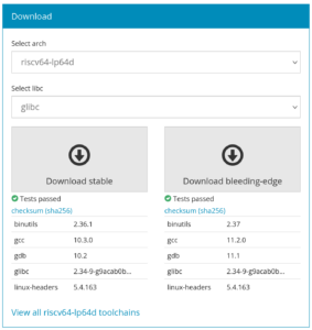
The so-called stable toolchains are now based on gcc 10.3.0, binutils 2.36.1, Linux headers 4.9, gdb 10.2, glibc 2.34, uClibc 1.0.39 and musl 1.2.2
The so-called bleeding-edge toolchains are now based on gcc 11.2, binutils 2.37, Linux headers 5.4, gdb 11.1, glibc 2.34, uClibc 1.0.39 and musl 1.2.2
The riscv64 toolchains (targeting the LP64 ABI) have been replaced by riscv64-lp64d toolchains (targeting the LP64D ABI), making them more generally useful.
Runtime testing using Qemu has been added for RISC-V 64-bit, m68k-68xxx and OpenRISC.
The gdb cross-debugger is now compiled with both Python and TUI support.
Internally, there’s been some significant refactoring of the scripts and Gitlab CI pipelines that control the build and testing of those toolchains. Many thanks to Romain Naour for providing the ground work that enabled this refactoring.
The toolchains can be directly downloaded from toolchains.bootlin.com. We have also submitted a patch to Buildroot that updates those toolchains, which are directly usable in Buildroot as external toolchains.
Bootlin has been delivering training courses in the field of Embedded Linux since its creation in 2004, delivering over 430 courses to more than 4500 engineers just since 2009, in over 40 countries, with a high-level of quality and a full transparency, with fully open training materials and publicly available training evaluations.
In France, a new quality certification brand for training and skills development service providers, called Qualiopi, has been created and is going to be needed starting January 1, 2022 for French training providers who want to deliver services to French customers who use public funding for training courses. For more details about Qualiopi, see this page in English, or the official page from the French Ministry, in French.
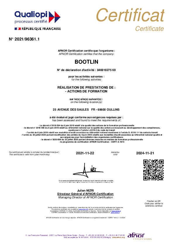
Bootlin has gone through the Qualiopi certification process, making a number of improvements to how we deliver and manage our training courses along the way, and we are happy to announce that Bootlin, at the first attempt, was successfully certified as a Qualiopi compliant training service provider. See our certificate, which can also be verified on the AFNOR certification authority website.
We are proud of this result, which shows our commitment to delivering high quality training courses to all our customers. Do not hesitate to look at our training courses portfolio and contact us if you are interested.
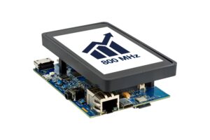
Back in 2019, ST released a brand new processor family, the STM32MP1, whose members are currently based on a dual Cortex-A7 to run Linux combined with one Cortex-M4 to run bare-metal applications, together with a wide range of peripherals.
Following the release of this new platform, Bootlin ported its Embedded Linux and Yocto training courses to be available on STM32MP1, and also published a long series of tutorials showing how to use Buildroot to build an embedded Linux system on STM32MP1: part 1, part 2, part 3, part 4, part 5, part 6 and part 7.
We are happy to announce that we have partnered with ST to develop an improved support of Buildroot on STM32MP1, which is materialized by a Buildroot BR2_EXTERNAL available on Github at https://github.com/bootlin/buildroot-external-st. In Buildroot, a BR2_EXTERNAL is an extension of the core Buildroot, with additional configurations and/or packages.
This BR2_EXTERNAL tree is an extension of Buildroot 2021.02, which provides four example Buildroot configuration to easily get started on STM32MP1 platforms:
st_stm32mp157a_dk1, building a basic Linux system for the STM32MP1 Discovery Kit 1 platform, with a minimal Linux root filesystem
st_stm32mp157c_dk2, building a basic Linux system for the STM32MP1 Discovery Kit 2 platform, with a minimal Linux root filesystem
st_stm32mp157a_dk1_demo, building a much more featureful Linux system for the STM32MP1 Discovery Kit 1 platform, with Linux root filesystem that allows to run Qt5 applications with OpenGL acceleration on the HDMI output, that supports audio, demonstrates the usage of the Cortex-M4, uses OP-TEE, and more.
st_stm32mp157c_dk2_demo, building a much more featureful Linux system for the STM32MP1 Discovery Kit 2 platform, with Linux root filesystem that allows to run Qt5 applications with OpenGL acceleration on both the integrated DSI display and HDMI output, that supports audio, WiFi and Bluetooth, demonstrates the usage of the Cortex-M4, uses OP-TEE, and more.
This BR2_EXTERNAL is designed to work with Buildroot 2021.02, with only a small set of modifications, which since then have been integrated in upstream Buildroot, ensuring that STM32MP1 users can directly use upstream Buildroot for their projects.
This Buildroot support is using the latest software components from the recently released 3.1 BSP from ST (see release notes), so it is based on Linux 5.10, U-Boot 2020.10, TF-A 2.4 and OP-TEE 3.12. We will keep this BR2_EXTERNAL updated with newer releases of the ST BSP.
A number of years ago, the French tax system has created a tax incentive mechanism called Crédit Impôt Recherche (Research Tax Credit) that allows startups and innovative companies to get tax deductions corresponding to a fraction of their research and development costs. This allows French companies to more easily invest in research and development activities.
In 2021, Bootlin has initiated the process to be eligible to this tax incentive mechanism, and we are happy to announce that after studying Bootlin’s expertise, engineering experience and achievements, the French tax administration has confirmed that Bootlin can deliver research and development activities fulfilling the Crédit Impôt Recherche criteria to its customers. This means that Bootlin customers in France can now integrate the cost of Bootlin engineering services that correspond to research and development activities into their Crédit Impôt Recherche and receive a tax incentive corresponding to up to 30% of the cost of our engineering services.
For our customers outside of France, this tax incentive is obviously not available, but the certification of Bootlin by the French tax administration as a company able to deliver research and development activities is another testimonial of our strong technical expertise in our field of Embedded Linux and Linux kernel development.
 The entire team at Bootlin is extremely happy to welcome Luca Ceresoli, who started working with us on March 1, 2022. Based in Italy, Luca is the first employee of Bootlin based outside of France, and we plan to continue to expand our hiring in a similar way in the future.