This article follows two earlier blog posts about Device Tree overlays:
- Using Device Tree Overlays, example on BeagleBone boards
- Device Tree: Supporting Similar Boards – The BeagleBone Example
Introduction
As explained in the first two blog posts, the BeagleBone boards are supported by a wide number of extension boards, called capes.
When such a cape is plugged in, the description of the devices connected to the board should be updated accordingly. As the available hardware is described by a Device Tree, the added devices on the cape should be described using a Device Tree Overlay, as described in the first blog post.
As explained in this post too, the bootloader is today’s standard place for loading Device Tree Overlays on top of the board’s Device Tree. Once you know which capes are plugged in, you can load them in U-Boot and boot Linux as in the following example:
load mmc 0:1 0x81000000 zImage
load mmc 0:1 0x82000000 am335x-boneblack.dtb
fdt addr 0x82000000
fdt resize 8192
load mmc 0:1 0x83000000 overlays/BBORG_RELAY-00A2.dtbo
fdt apply 0x83000000
bootz 0x81000000 - 0x82000000
This mechanism works fine, but every time you plug in a different cape, you have to tweak this sequence of commands to load the right overlay (the .dtbo file). This would be great if each cape could be detected automatically and so could be the corresponding overlays.
Actually, all this is possible and already supported in mainline U-Boot starting from version 2021.07. That’s what this article is about.
Accessing cape information
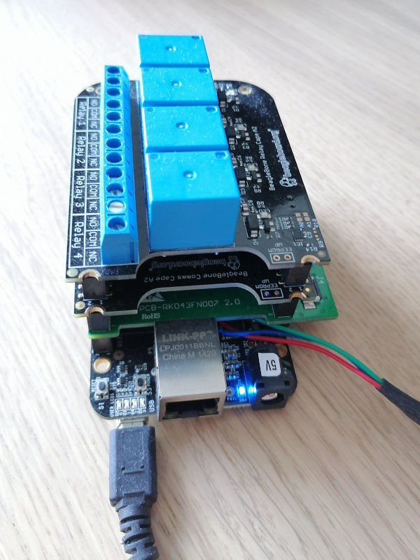
Each cape has to contain an I2C EEPROM describing itself, according to the Cape EEPROM Contents specification.
To identify which capes are plugged in, all you have to do is read the connected EEPROMs. You can test by yourself by booting a BeagleBone with a Debian image, and dumping the EEPROM contents as in the following example:
hexdump -C /sys/bus/i2c/devices/2-0054/eeprom
00000000  aa 55 33 ee 41 31 52 65  6c 61 79 20 43 61 70 65  |.U3.A1Relay Cape|
00000010  00 00 00 00 00 00 00 00  00 00 00 00 00 00 00 00  |................|
00000020  00 00 00 00 00 00 30 30  41 32 42 65 61 67 6c 65  |......00A2Beagle|
00000030  42 6f 61 72 64 2e 6f 72  67 00 42 42 4f 52 47 5f  |Board.org.BBORG_|
00000040  52 45 4c 41 59 00 00 00  00 00 00 00 47 48 49 31  |RELAY.......GHI1|
00000050  38 32 37 30 34 37 32 00  ff ff ff ff ff ff ff ff  |8270472.........|
00000060  ff ff ff ff ff ff ff ff  ff ff ff ff ff ff ff ff  |................|
*
...
Of course, the above kind of command only works if the corresponding Device Tree Overlays are loaded. Otherwise, the Linux kernel won’t know that the I2C EEPROMs are available.
The U-Boot extension manager
In the latest Debian images proposed by BeagleBoard.org at the time of this writing, there is already a mechanism to detect the plugged capes based on the information on their I2C EEPROM. However, that was a custom mechanism, and BeagleBoard.org contracted Bootlin to implement a more generic mechanism in the official version of U-Boot.
This generic mechanism was implemented by my colleague Köry Maincent and added to U-Boot (since version 2021.07) by this commit.
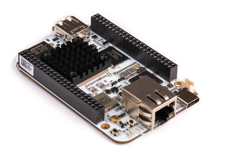
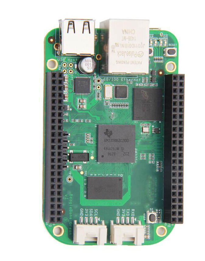
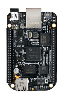
Let’s test this mechanism by building and booting our own image. The following instructions apply to the BeagleBone Black board.
SD card preparation
Using cfdisk or a similar tool, prepare a micro-SD card with at least one partition which you mark as “Bootable”. Then format it with the FAT32 filesystem:
sudo mkfs.vfat -F 32 -n boot /dev/mmcblk0p1
Now, remove and plug the micro-SD card back in again. It should automatically be mounted on /media/$USER/boot.
Compiling U-Boot
We first need to install a cross-compiling toolchain if you don’t have one yet. Here’s how to do this on Ubuntu:
sudo apt install gcc-arm-linux-gnueabihf
export CROSS_COMPILE=arm-linux-gnueabihf-
Now, let’s use the latest version of U-Boot at the time of this writing.
git clone git://git.denx.de/u-boot.git
cd u-boot
git checkout v2022.04
make am335x_evm_defconfig
make menuconfig
In the configuration interface, add the new extension command by setting CONFIG_CMD_EXTENSION=y. You can then compile U-Boot:
make
cp MLO u-boot.img /media/mike/boot
Compiling Linux and Device Tree Overlays
Now, let’s compile the latest 5.10 Linux kernel supported by BeagleBoard.org.
First, download the root filesystem (generated by Buildroot, with this configuration file) which we will include in the Linux kernel as an initramfs.
Then, let’s get the kernel sources and configure them:
git clone https://github.com/beagleboard/linux.git
cd linux
git checkout 5.10.100-ti-r40
export CROSS_COMPILE=arm-linux-gnueabihf-
export ARCH=arm
make omap2plus_defconfig
make menuconfig
In the configuration interface, enable compiling the Device Tree Overlays with CONFIG_OF_OVERLAY=y. Also set CONFIG_INITRAMFS_SOURCE="../rootfs.cpio". You can now compile the kernel and the Device Trees, and deploy them to the micro-SD card:
make
cp arch/arm/boot/zImage /media/$USER/boot/
cp arch/arm/boot/dts/am335x-boneblack.dtb /media/$USER/boot/
mkdir /media/$USER/boot/overlays
cp arch/arm/boot/dts/overlays/*.dtbo /media/$USER/boot/overlays/
sudo umount /media/$USER/boot
Configuring U-Boot and using the “extension” command
Now insert the micro-SD card in the BeagleBone Black. Connect the capes that you own. Then power on the board while holding the USR button (close to the USB host port).
On the serial line, you should see U-Boot 2022.04 starting. Interrupt the countdown by pressing any key, to access the U-Boot prompt:
U-Boot SPL 2022.04 (Apr 06 2022 - 15:04:53 +0200) Trying to boot from MMC1 U-Boot 2022.04 (Apr 06 2022 - 15:04:53 +0200) CPU : AM335X-GP rev 2.1 Model: TI AM335x BeagleBone Black DRAM: 512 MiB Core: 150 devices, 14 uclasses, devicetree: separate WDT: Started wdt@44e35000 with servicing (60s timeout) NAND: 0 MiB MMC: OMAP SD/MMC: 0, OMAP SD/MMC: 1 Loading Environment from FAT... Unable to read "uboot.env" from mmc0:1...not set. Validating first E-fuse MAC Net: eth2: ethernet@4a100000, eth3: usb_ether Hit any key to stop autoboot: 0 =>
Let’s try the extension manager now. First, we load the kernel image and Device Tree Binary (DTB) for the board:
=> fatload mmc 0:1 0x81000000 zImage
6219488 bytes read in 408 ms (14.5 MiB/s)
=> fatload mmc 0:1 0x82000000 am335x-boneblack.dtb
64939 bytes read in 10 ms (6.2 MiB/s)
Then, we set the RAM address where each Device Tree Overlay will be loaded:
=> setenv extension_overlay_addr 0x88080000
And define the command to load the overlays:
setenv extension_overlay_cmd 'echo loading ${extension_overlay_name}; fatload mmc 0:1 ${extension_overlay_addr} overlays/${extension_overlay_name}'
saveenv
Then, let U-Boot know where the DTB was loaded:
fdt addr 0x82000000
You can then scan for extension boards:
=> extension scan
BeagleBone Cape: Relay Cape (0x54)
BeagleBone Cape: BB-CAPE-DISP-CT43 (0x55)
BeagleBone Cape: Industrial Comms Cape (0x56)
Found 3 extension board(s).
Optionally, you can get a full listing after extension scan:
=> extension list
Extension 0: Relay Cape
	Manufacturer: 		BeagleBoard.org
	Version: 		00A2
	Devicetree overlay: 	BBORG_RELAY-00A2.dtbo
	Other information:
Extension 1: BB-CAPE-DISP-CT43
	Manufacturer: 		Embest
	Version: 		00A0
	Devicetree overlay: 	BB-CAPE-DISP-CT4-00A0.dtbo
	Other information:
Extension 2: Industrial Comms Cape
	Manufacturer: 		BeagleBoard.org
	Version: 		00A2
	Devicetree overlay: 	BBORG_COMMS-00A2.dtbo
	Other information:
Taking the relay cape as an example, you can see that the name of the Device Tree overlay was derived from the description in its EEPROM, which we dumped earlier.
Now, everything’s ready to load the overlay for the first cape (number 0):
=> extension apply 0
loading BBORG_RELAY-00A2.dtbo
1716 bytes read in 5 ms (335 KiB/s)
Or for all capes:
=> extension apply all
loading BBORG_RELAY-00A2.dtbo
1716 bytes read in 5 ms (335 KiB/s)
loading BB-CAPE-DISP-CT4-00A0.dtbo
5372 bytes read in 5 ms (1 MiB/s)
loading BBORG_COMMS-00A2.dtbo
1492 bytes read in 4 ms (364.3 KiB/s)
We are now ready to set a generic command that will automatically load all the overlays for the supported capes, whatever they are, and then boot the Linux kernel:
setenv bootargs console==ttyS0,115200n8
setenv bootcmd 'fatload mmc 0:1 0x81000000 zImage; fatload mmc 0:1 0x82000000 am335x-boneblack.dtb; fdt addr 0x82000000; extension scan; extension apply all; bootz 0x81000000 - 0x82000000'
saveenv
Reboot your board and you should see:
6228224 bytes read in 526 ms (11.3 MiB/s)
93357 bytes read in 10 ms (8.9 MiB/s)
BeagleBone Cape: Relay Cape (0x54)
BeagleBone Cape: BB-CAPE-DISP-CT43 (0x55)
BeagleBone Cape: Industrial Comms Cape (0x56)
Found 3 extension board(s).
loading BBORG_RELAY-00A2.dtbo
1716 bytes read in 5 ms (335 KiB/s)
loading BB-CAPE-DISP-CT4-00A0.dtbo
5372 bytes read in 5 ms (1 MiB/s)
loading BBORG_COMMS-00A2.dtbo
1492 bytes read in 4 ms (364.3 KiB/s)
Kernel image @ 0x81000000 [ 0x000000 - 0x5f0900 ]
## Flattened Device Tree blob at 82000000
   Booting using the fdt blob at 0x82000000
   Loading Device Tree to 8ffe4000, end 8fffffff ... OK

Starting kernel ...

[    0.000000] Booting Linux on physical CPU 0x0
[    0.000000] Linux version 5.10.100 (mike@mike-laptop) (arm-linux-gnueabihf-gcc (Ubuntu 9.4.0-1ubuntu1~20.04.1) 9.4.0, GNU ld (GNU Binutils for Ubuntu) 2.34) #8 SMP Wed Apr 6 16:25:24 CEST 2022
...
To double check that the overlays were taken into account, you can log in a the root user (no password) and type this command:
# ls  /proc/device-tree/chosen/overlays/
BB-CAPE-DISP-CT4-00A0.kernel  BBORG_RELAY-00A2.kernel
BBORG_COMMS-00A2.kernel       name
Note: all the files used here, including the resulting U-Boot environment file, are available in this archive. All you have to do is extract the archive in a FAT partition with the bootable flag, and then you’ll be ready to boot your board with it, without any manipulation to perform in U-Boot.
How to add support for a new board
To prove that the new extension board manager in U-Boot was generic, Köry Maincent used it to support three different types of boards:
- BeagleBone boards based on the AM3358 SoC from TI
- The BeagleBone AI board, based on the AM5729 SoC from TI
- The CHIP computer, based on the Allwinner R8 CPU, and its DIP extension boards.
To support a new board and its extension boards, the main thing to implement is the extension_board_scan() function for your board.
A good example to check is this commit from Köry which introduced cape detection capabilities for the TI CPUs and this second commit that enabled the mechanism on AM57xx (BeagleBone AI). A good ideas is also to check the latest version of board/ti/common/cape_detect.c in U-Boot’s sources.
Summary
The U-Boot Extension Board Manager is a feature in U-Boot which allows to automatically detect extension boards, provided the hardware makes such a detection possible, and automatically load and apply the corresponding Device Tree overlays. It was contributed by Köry Maincent from Bootlin, thanks to funding from BeagleBoard.org.
At the time of this writing, this functionality is supported on the BeagleBone boards (AM335x and AM57xx), on the CHIP computer (Allwinner R8), and since more recently, on Compulab’s IOT-GATE-iMX8 gateways.
With the combination of this blog post and the former two (see the links at the beginning), it should be clear how a specification can be written to use a combination of Device Tree symbols, Udev rules and extension board identifiers to make expansion header hardware “just work” when plugged in to various boards with compatible headers. BeagleBoard.org would be proud if our example inspired other community board maintainers.
References
- BeagleBoard.org blog post: Using Device Tree Overlays, example on BeagleBone boards
- Live Embedded Event conference presentation: Device Tree overlays and U-boot extension board management (video)
Bootlin would like to thank BeagleBoard.org for funding the development and deployment of this infrastructure in mainline U-Boot, and the creation of these three blog posts on Device Tree overlays.
 Tomorrow, on May 18, the third edition of


 The entire team at Bootlin is extremely happy to welcome