Virtually all micro-controllers and micro-processors provide some form of timer counters. In the context of Linux, they are always used for kernel timers, but they can also sometimes be used for PWMs, or input capture devices able to measure external signals such as rotary encoders. In this blog post, we would like to illustrate how Linux can take advantage of such timer counters, by taking the example of the Microchip Timer Counter Block, and depict how its various features fit into existing Linux kernel subsystems.
Hardware overview
On Microchip ARM processors, the TCB (Timer Counter Block) module is a set of three independent, 16 or 32-bits, channels as illustrated in this simplified block diagram:
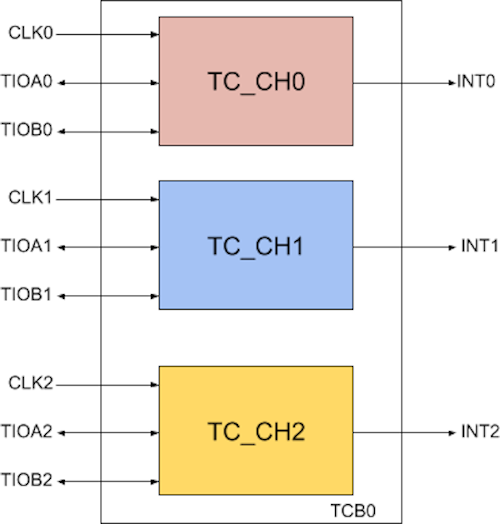
The exact number of TCB modules depends on which Microchip processor you’re using, this Microchip brochure gives the details. Most products have 6 or 9 timer counter channels available, which are grouped into two or three TCB modules, each having 3 channels.
Each TC channel can independently select a clock source for its counter:
- Internal Clock: sourced from either the system bus clock (often the highest rated one with pre-defined divisors), the slow clock (crystal oscillator) and for the Microchip SAMA5D2 and SAM9X60 SOC series there is even a programmable generic clock source (GCLK) specific to each peripheral.
- External Clock: based on the three available external input pins: TCLK0, TCLK1 or TCLK2.
The clock source choice should obviously be made depending on the accuracy required by the application.
The module has many functions declined in three different modes:
- The input capture mode is useful to capture input signals (e.g measure a signal period) through one of the six input pins (TIOAx/TIOBx) connected to each TC module. Each pin can act as trigger source for the counter and two latch register RA/RB can be loaded and compared with a third RC register. This mode is highly configurable with lots of feature to fine tune the capture (subsambling, clock inverting, interrupt, etc.).
- The waveform mode which provide the core function of TCs as all channels could be used as three independent free-running counters and it is also a mode used to generate PWM signals which gives an extra pool of PWMs
- The quadrature mode is only supported on the first TC module TCB0 and two (or three) channels are required, channel 0 will decode the speed or position on TIOA0/TIOB0, channel 1 (with TIOB1 input) can be configured to store the revolution or number of rotation. Finally if speed measurement is configured the channel 2 shall define a speed time base.Something important to note is that this mode actually is only part of Microchip SAMA5 and SAM9x60 family SOCs.
Software overview
On the software side in the Linux kernel, the different functionalities offered by the Microchip TCBs will be handled by three different subsystems, which we cover in the following sections.
Clocksource susbsystem
This subsystem is the core target of any TC module as it allows the kernel to keep track of the time passing (clocksource) and program timer interrupts (clockevents). The Microchip TCB has its upstream implementation in drivers/clocksource/timer-atmel-tcb.c that uses the waveform mode to provide both clock source and clock events. The older Microchip platforms have only 16-bit timer counters, in which case two channels are needed to implement the clocksource support. Newer Microchip platforms have 32-bit timer counters, and in this case only one channel is needed to implement clocksource. In both cases, only one channel is necessary to implement clock events.
In the timer-atmel-tcb driver:
- The clocksource is registered using a
struct clocksource structure which mainly provides a ->read() callback to read the current cycle count
- The clockevents is registered using a
struct tc_clkevt_device structure, which provides callbacks to set the date of the next timer event (->set_next_event()) and to change the mode of the timer (->set_state_shutdown(), ->set_state_periodic(), ->set_state_oneshot()).
From a user-space point of view, the clocksource and clockevents subsystems are not directly visible, but they are of course used whenever one uses time or timer related functions. The available clockevents are visible in /sys/bus/clockevents and the available clocksources are visible in /sys/bus/clocksource. The file /proc/timer_list also gives a lot of information about the timers that are pending, and the available timer devices on the platform.
PWM subsystem
This subsystem is useful for many applications (fan control, leds, beepers etc.), and provides both an in-kernel APIs for other kernel drivers to use, as well as a user-space API in /sys/class/pwm, documented at https://www.kernel.org/doc/html/latest/driver-api/pwm.html.
As far as PWM functionality is concerned, the Microchip TCB module is supported by the driver at drivers/pwm/pwm-atmel-tcb.c, which also uses the waveform mode. In this mode both channels pins TIOAx/TIOBx can be used to output PWM signals which allows to provide up to 6 PWM outputs per TCB. On a high-level, this PWM driver registers a struct pwm_ops structure that provides pointers to the important callback to setup and configure PWM outputs.
The current diver implementation has the drawback of using an entire TCB module as a PWM chip: it is not possible to use 1 channel of a TCB module for PWM, and the other channels of the same TCB module for other functionality. On platforms that have only two TCB modules, this means that the first TCB module is typically used for the clockevents/clocksource functionality described previously, and therefore only the second TCB module can be used for PWM.
We are however working on lifting this limitation: Bootlin engineer Alexandre Belloni has a patch series at https://github.com/alexandrebelloni/linux/commits/at91-tcb to address this. We aim at submitting this patch series in the near future.
Thanks to the changes of this patch series, we will be able to use PWM channels as follows:
- Configuring a 100KHz PWM signal on TIOAx:
# echo 0 > /sys/class/pwm/pwmchip0/export
# echo 10000 > /sys/class/pwm/pwmchip0/pwm0/period
# echo 1000 > /sys/class/pwm/pwmchip0/pwm0/duty_cycle
# echo 1 > /sys/class/pwm/pwmchip0/pwm0/enable
- Configuring a 100KHz PWM signal on TIOBx:
# echo 1 > /sys/class/pwm/pwmchip0/export
# echo 10000 > /sys/class/pwm/pwmchip0/pwm1/period
# echo 1000 > /sys/class/pwm/pwmchip0/pwm1/duty_cycle
# echo 1 > /sys/class/pwm/pwmchip0/pwm1/enable
One must note that both PWM signals of the same channel will share the same period even though we set it twice here as it is required by the PWM framework. The Microchip TCB takes the period from the RC register and RA/RB respectively for TIOAx/TIOBx duty cycles.
Counter subsystem
The Linux kernel counter subsystem, located in drivers/counter/ is much newer than the clocksource, clockevents and PWM subsystems described previously. Indeed, it is only in 2019 that it was added to the Linux kernel, and so far it contains only 5 drivers. This subsystem abstracts a timer counter as three entities: a Count that stores the value incremented or decremented from a measured input Signal and a Synapse that will provide edge-based trigger source.
This subsystem was therefore very relevant to expose the input capture and quadrature decoder modes of the Microchip TCB module, and we recently submitted a patch series that implements a counter driver for the Microchip TCB module. The driver instantiates and registers a struct counter_device structure, with a variety of sub-structures and callbacks that allow the core counter subsystem to use the Microchip TCB module and expose its input capture and quadrature decoder features to user-space.
The current user-space interface of the counter subsystem works over sysfs and is documented at https://www.kernel.org/doc/html/latest/driver-api/generic-counter.html. For example, to read the position of a rotary encoder connected to a TCB module configured as a quadradure decoder, one would do:
# cd /sys/bus/counter/devices/counter0/count0/
# echo "quadrature x4" > function
# cat count
0
However, when the device connected to the TCB is a rotary encoder, it would be much more useful to have it exposed to user-space as a standard input device so that all existing graphical libraries and frameworks can automatically make use of it. Rotary encoders connected to GPIOs can already be exposed to user-space as input devices using the rotary_encoder driver. Our goal was to achieve the same, but with a rotary encoder connected to a quadrature decoder handled by the counter subsystem. To this end, we submitted a second patch series, which:
- Extends the counter subsystem with an in-kernel API, so that counter devices can not only be used from user-space using sysfs, but also from other kernel subsystems. This is very much like the IIO in-kernel API, which is used in a variety of other kernel subsystems that need access to IIO devices.
- A new rotary-encoder-counter driver, which implements an input device based on a counter device configured in quadrature decoder mode.
Thanks to this driver, we get an input device for our rotary encoder, which can for example be tested using evtest to decode the input events that occur when rotating the rotary encoder:
# evtest /dev/input/event1
Input driver version is 1.0.1
Input device ID: bus 0x19 vendor 0x0 product 0x0 version 0x0
Input device name: "rotary@0"
Supported events:
Event type 0 (EV_SYN)
Event type 2 (EV_REL)
  Event code 0 (REL_X)
Properties:
Testing ... (interrupt to exit)
Event: time 1325392910.906948, type 2 (EV_REL), code 0 (REL_X), value 2
Event: time 1325392910.906948, -------------- SYN_REPORT ------------
Event: time 1325392911.416973, type 2 (EV_REL), code 0 (REL_X), value 1
Event: time 1325392911.416973, -------------- SYN_REPORT ------------
Event: time 1325392913.456956, type 2 (EV_REL), code 0 (REL_X), value 2
Event: time 1325392913.456956, -------------- SYN_REPORT ------------
Event: time 1325392916.006937, type 2 (EV_REL), code 0 (REL_X), value 1
Event: time 1325392916.006937, -------------- SYN_REPORT ------------
Event: time 1325392919.066977, type 2 (EV_REL), code 0 (REL_X), value 1
Event: time 1325392919.066977, -------------- SYN_REPORT ------------
Event: time 1325392919.576988, type 2 (EV_REL), code 0 (REL_X), value 2
Event: time 1325392919.576988, -------------- SYN_REPORT ------------
Device Tree
From a Device Tree point of view, the representation is a bit more complicated than for many other hardware blocks, due to the multiple features offered by timer counters. First of all, in the .dtsi file describing the system-on-chip, we have a node that describes each TCB module. For example, for the Microchip SAMA5D2 system-on-chip, which has two TCB modules, we have in arch/arm/boot/dts/sama5d2.dtsi:
tcb0: timer@f800c000 {
	compatible = "atmel,at91sam9x5-tcb", "simple-mfd", "syscon";
	#address-cells = <1>;
	#size-cells = <0>;
	reg = <0xf800c000 0x100>;
	interrupts = <35 IRQ_TYPE_LEVEL_HIGH 0>;
	clocks = <&pmc PMC_TYPE_PERIPHERAL 35>, <&clk32k>;
	clock-names = "t0_clk", "slow_clk";
};

tcb1: timer@f8010000 {
	compatible = "atmel,at91sam9x5-tcb", "simple-mfd", "syscon";
	#address-cells = <1>;
	#size-cells = <0>;
	reg = <0xf8010000 0x100>;
	interrupts = <36 IRQ_TYPE_LEVEL_HIGH 0>;
	clocks = <&pmc PMC_TYPE_PERIPHERAL 36>, <&clk32k>;
	clock-names = "t0_clk", "slow_clk";
};
This however does not define how each TCB module and each channel is going to be used. This happens at the board level, by adding sub-nodes to the appropriate TCB module node.
First, each board needs to at least define which TCB module and channels should be used for the clocksource/clockevents. For example, arch/arm/boot/dts/at91-sama5d2_xplained.dts has:
tcb0: timer@f800c000 {
	timer0: timer@0 {
		compatible = "atmel,tcb-timer";
		reg = <0>;
	};

	timer1: timer@1 {
		compatible = "atmel,tcb-timer";
		reg = <1>;
	};
};
As can be seen in this example, the timer@0 and timer@1 node are sub-nodes of the timer@f800c000 node. The SAMA5D2 has 32-bit timer counters, so only one channel is needed for the clocksource, and another channel is needed for clock events. Older platforms such as AT91SAM9260 would need:
tcb0: timer@fffa0000 {
	timer@0 {
		compatible = "atmel,tcb-timer";
		reg = <0>, <1>;
	};

	timer@2 {
		compatible = "atmel,tcb-timer";
		reg = <2>;
	};
};
Where the first instance of atmel,tcb-timer uses two channels: on AT91SAM9260, each channel is only 16-bit, so we need two channels for clocksource. This is why we have reg = <0>, <1> in the first sub-node.
Now, to use some TCB channels as PWMs, with the new patch series proposed by Alexandre, one would for example use:
&tcb1 {
	tcb1_pwm0: pwm@0 {
		compatible = "atmel,tcb-pwm";
		#pwm-cells = <3>;
		reg = <0>;
		pinctrl-names = "default";
		pinctrl-0 = <&pinctrl_tcb1_tioa0 &pinctrl_tcb1_tiob0>;
	};

	tcb1_pwm1: pwm@1 {
		compatible = "atmel,tcb-pwm";
		#pwm-cells = <3>;
		reg = <1>;
		pinctrl-names = "default";
		pinctrl-0 = <&pinctrl_tcb1_tioa1>;
	};
};
To use the two first channels of TCB1 as PWMs. This would provide two separate PWM devices visible to user-space, and to other kernel drivers.
Otherwise, to use a TCB as a quadrature decoder, one would use the following piece of Device Tree. Note that we must use the TCB0 module as it is the only one that supports quadrature decoding. This means that the atmel,tcb-timer nodes for clocksource/clockevents support have to use TCB1.
&tcb0 {
	qdec: counter@0 {
		compatible = "atmel,tcb-capture";
		reg = <0>, <1>;
		pinctrl-names = "default";
		pinctrl-0 = <&pinctrl_qdec_default>;
	};
};
A quadrature decoder needs two channels, hence the reg = <0>, <1>.
And if in addition you would like to setup an input device for the rotary encoder connected to the quadrature decoder, you can add:
rotary@0 {
	compatible = "rotary-encoder-counter";
	counter = <&qdec>;
	qdec-mode = <7>;
	poll-interval = <50>;
};
Note that this is not a sub-node of the TCB node, the rotary encoder needs to be described at the top-level of the Device Tree, and has a reference to the TCB channels used as quadrature decoder by means of the counter = <&qdec>; phandle.
Of course, these different capabilities can be combined. For example, you could use the first two channels of TCB0 to implement a quadrature decoder using the counter subsystem, and the third channel of the same TCB module for a PWM. TCB1 is used for clocksource/clockevents. In this case, the Device Tree would look like this:
&tcb0 {
	counter@0 {
		compatible = "atmel,tcb-capture";
		reg = <0>, <1>;
		pinctrl-names = "default";
		pinctrl-0 = <&pinctrl_qdec_default>;
	};

	pwm@2 {
		compatible = "atmel,tcb-pwm";
		#pwm-cells = <3>;
		reg = <2>;
		pinctrl-names = "default";
		pinctrl-0 = <&pinctrl_tcb1_tioa1>;
	};
};

&tcb1 {
	timer@0 {
		compatible = "atmel,tcb-timer";
		reg = <0>, <1>;
	};

	timer@2 {
		compatible = "atmel,tcb-timer";
		reg = <2>;
	};
};
Conclusion
We hope that this blog post was useful to understand how Linux handles timer counters, and what are the Linux kernel subsystems that are involved. Even though we used the Microchip TCB to illustrate our discussion, the concepts all apply to the timer counters of other platforms that would offer similar features.
 Over the past few years, we have been contributing to the OP-TEE project the support for the Microchip SAMA5D2 processor family, and we also helped with enabling OP-TEE on the Microchip SAMA7 processor family.