At Bootlin, we focus on Embedded Linux development and support, and these embedded devices often have a network interface, be-it an Ethernet port, a Wireless chip or some other kind of communication channel that falls under the Linux Networking Stack’s framework.
So it’s always interesting to see what the rest of the community is working on, and meet in real life people we interact with on the netdev mailing list.
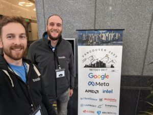
That’s why this year, Alexis Lothoré and Maxime Chevallier flew to Vancouver to participate to the Netdev Conference, a 5 days event organised by the Netdev Society, a small non-profit run by volunteers dedicated to holding this event.
Most talks at Netdev are not directly covering topics we’re actively working on, but it’s always refreshing to see these new exciting technologies that could trickle their way down to the embedded world a few years from now. It is also always pretty interesting to stay up to date about challenges encountered by other parts of the networking industry, at scales way different than the ones we are used to.
We learned for example what CXL is about, what it brings and the effort that are made to design new networking hardware around this technology to change the way we think about datacenter networking.
When we attended Netdev 0x13 in 2019, QUIC was one of the hot topics. This year, Homa was under the spotlight with talks on what it is, and how this new protocol could address some of TCP’s problems.
Like all previous editions, we learned all the progress that were made with TC and its future, new ways of bypassing the kernel stack, BPF integration in the kernel, along with XDP which continued to be more and more powerful.
Another hot topic in the kernel is the introduction of the Rust language, and the network subsystem is a pretty relevant target for the new features brought by the language. As a consequence, Rust subsystem maintainers Miguel Ojeda and Wedson Almeida Filho gave an overview of Rust benefits compared to traditional C code, and then showed a step-by-step implementation of a kernel-side TCP server module. While this example is not perfectly representative of classic network-related drivers we usually write, it was a nice showcase of current state of kernel APIs abstractions in Rust.
We also discovered the new use-case that is now driving most of the datacenter networking efforts, which is without surprise AI and Machine Learning. Turns out, if you want your ChatGPT to answer up-to-date replies without having to wait for too long, you need a powerful and well-organized datacenter for the training part, and networking engineering takes a big part in it to keep all those GPUs fed at a relevant pace.
This lead to the devmem TCP effort, which started to feel a bit familiar for us as it uses dma-buf, which we also sometimes use on multimedia pipelines. The ML and AI topic was introduced to us by the wonderful Keynote session given by Manya Ghobadi, who got all the audience captivated by how AI and ML works, what AI workloads requires in terms of network traffic scheduling, datacenter topology and computing hardware that uses optical computing.
On the final day, we even had a visit from Jakub Kicinski (one of the co-maintainers of Linux networking tree), presenting what he had been working on, and gave us an update on the netdev development statistics (and basically, his main point is that we do need to review more patches).
For the first time, there was a talk from Bootlin at netdev, as Maxime presented one of the topics he’s been working on lately : Improving multi-PHY and multi-port interfaces support. Although it was one of the only talks focusing on the low-levels aspects of the Ethernet stack, it triggered some discussions and interest from the community, which will help further improving the ongoing work.
The slides and videos of the event will be published at some point in the future, we will for sure mention this to our readers when it becomes available.
We’ll conclude this short feedback by thanking once again the Netdev Board members, organizers, speakers and the audience for this great event.
We’ll come back 🙂
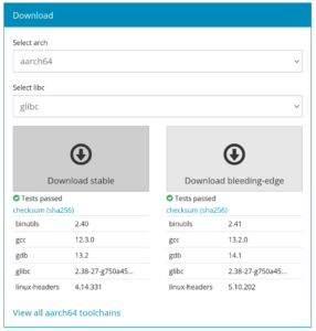 Our toolchains.bootlin.com project offers a wide range of freely available pre-compiled cross-compilation toolchains, updated on a regular basis.

 Bootlin will be at the