 The Embedded Open Source Summit will take place on April 16-18 in Seattle (Washington, US), with a wide range of events, including the Embedded Linux Conference which is of particular interest to Bootlin considering our core expertise.
As usual, a significant fraction of the Bootlin team will attend the event, with no less than 11 engineers from our team going to Seattle: Alexandre Belloni, Bastien Curutchet, Grégory Clement, Jérémie Dautheribes, João Marcos Costa, Köry Maincent, Louis Chauvet, Luca Ceresoli, Maxime Chevallier, Thomas Petazzoni and an additional engineer who will join us at the beginning of April. At Bootlin, all engineers, regardless of their seniority level, are offered the possibility of attending up to 2 conferences per year, to expand their knowledge on embedded Linux topics, to create connections with the community and therefore provide better services to our customers.
In addition to participating, we will also be delivering no less than 4 talks at the conference:
- In the Kernel Trenches: Mastering Ethernet Drivers on Linux – Maxime Chevallier, Bootlin
An Ethernet Controller driver in linux is a complex piece of software, with many entrypoints and callbacks, even for a basic Ethernet Controller we can find in Embedded Systems. In this talk, we’ll take a tour of what’s inside a typical Ethernet driver. We’ll start with the base of what every network driver provides, even non-Ethernet ones, a net_device. We will discuss the various required steps to get a basic driver working, ranging from simple initialization, queue setup, DMA mappings, before diving into more advances topics such as the NAPI loop implementation, memory-management through the page-pool API and finally XDP, which is now getting implemented in more and more drivers. We’ll continue the tour through the ethernet-specific bits, such as the ethtool operations, and phylink support to interact with a potential Ethernet PHY, and discuss a little bit about the specifics of embedded Ethernet Controllers, where low-level configuration for a PCS or some Serdes lanes might be required. Finally, we’ll discuss about testing and debugging tools that can be useful to help you in your driver development, but also in debugging and optimizing existing drivers.
- Introduction to DAPM, Linux Power Management for Embedded Audio Devices – Luca Ceresoli, Bootlin
DAPM (Digital Audio Power Management) is the part of ASoC (Alsa for System-on-Chips) that dynamically turns on and off power to various parts of the audio hardware in embedded Linux systems. DAPM is very useful, but not well known and documented. After introducing the motivations for DAPM and how it models the hardware, Luca will present some user space tools to understand how DAPM works at runtime. He will then show what DAPM practically means for developers, with code examples of how to add DAPM support to device drivers. Finally he will mention some improvements to the DAPM tooling and documentation.
- Unlocking the Potential of Suspend to RAM Using Linux in a Multi-Core, Multi-Firmware Automotive SoC – Grégory Clement, Bootlin
Fast booting in modern, complex System-on-Chips (SoCs) demands innovative solutions. This talk delves into the intricacies of implementing Suspend to RAM (S2R) on a sophisticated SoC featuring diverse CPU cores—high-performance A72, real-time R5, and low-power M3—as well as multiple firmware components, including open-source ones like TF-A, U-Boot, and OP-TEE. We begin with a hardware overview of the TI DRA821 SoC from the Jacinto family, emphasizing the open-source firmware utilized in the boot process. The focus then shifts to presenting a practical approach for integrating S2R into this multifaceted platform. Notably, our implementation poses a unique challenge: the SoC is entirely powered off during S2R, adding an extra layer of complexity. Join us as we share insights into the hurdles encountered and resolved during the implementation, along with a discussion on the outstanding challenges for which we’ve devised viable solutions. This session offers a comprehensive exploration into the software, including bootloaders and the Linux kernel, as well as the hardware aspects, showcasing a real-world approach to bringing Suspend to RAM to life on a cutting-edge automotive SoC.
- Adding Support for Power Over Ethernet (PoE or IEEE Clause 33) to Linux Network Stack – Köry Maincent, Bootlin
Power over Ethernet (PoE) is a technology that combines electrical power and data transmission over a single Ethernet cable. It eliminates the need for separate power sources, simplifying installations for devices like IP cameras, and VoIP phones. In this presentation, we’ll initially delve into Power over Ethernet (PoE), It debuted in IEEE Clause 33 without explicit reference to the PoE nomenclature. We will look at what currently exists in the Linux kernel and user space to support PoE. We’ll continue our discussion with some details of the Linux implementation currently in development and the PSE core changes brought by this new support. The PSE framework core and bindings happen to need modification as it was not prepared for the PoE specificities. In parallel to these extensions of the PSE framework, we developed Linux kernel drivers for two distinct PoE controllers: the Microchip PD692x0 and the Texas Instruments TPS23881. Finally, we will look into the mainline status, the things that still need to be merged and the future features that need development. This PoE Linux support is sponsored and funded by DENT Project.
See the full schedule of talks.
The Embedded Open Source Summit isn’t just about the presentations—it’s about forging connections, sharing ideas, and exploring opportunities. Join us for insightful conversations with the Bootlin team, where you can discuss your projects, ambitions, and maybe even discover new career pathways.
And mark your calendars because following the summit, our CEO Thomas Petazzoni will be in the Bay Area until April 24, ready to delve deeper into your embedded Linux needs.
So, whether you’re a seasoned veteran or a curious newcomer, don’t miss out on the Embedded Open Source Summit 2024. We’ll see you there!
 We are very happy to welcome in our team Richard Genoud, who joined us at the beginning of April, and already participated to his first conference with Bootlin by attending the Embedded Linux Conference this week.
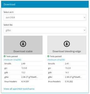
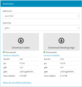 We just released version 2024.02 of the