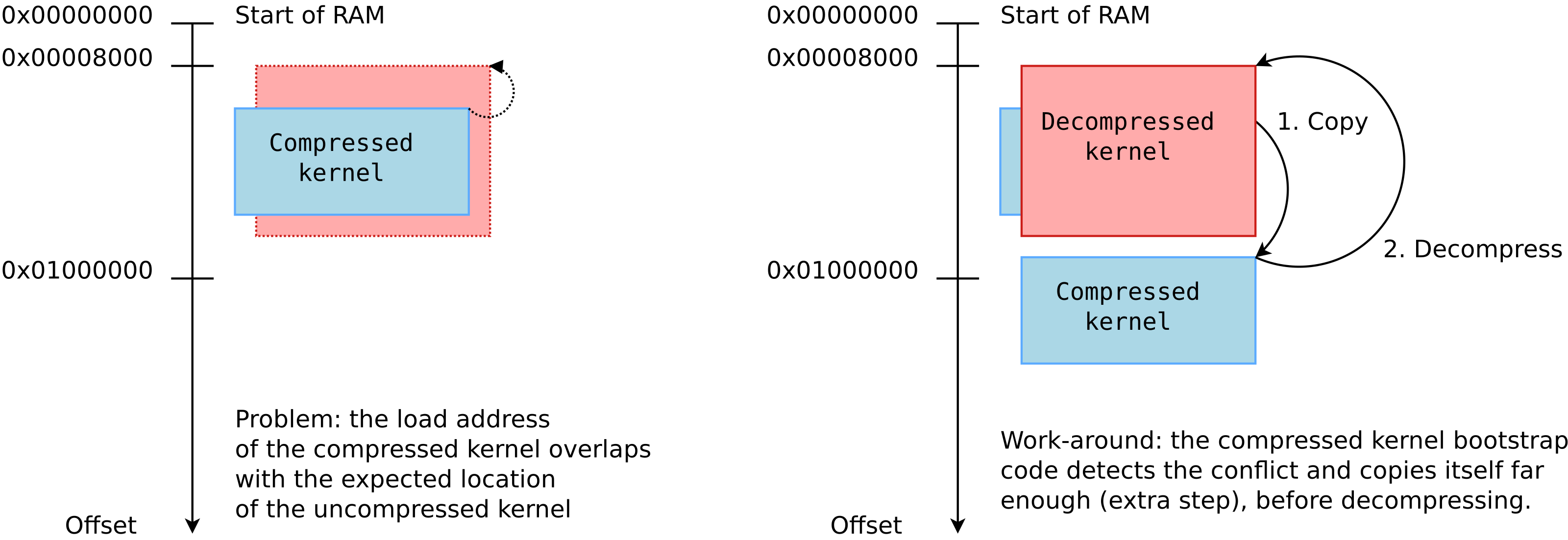
When the compressed and uncompressed kernel images overlap
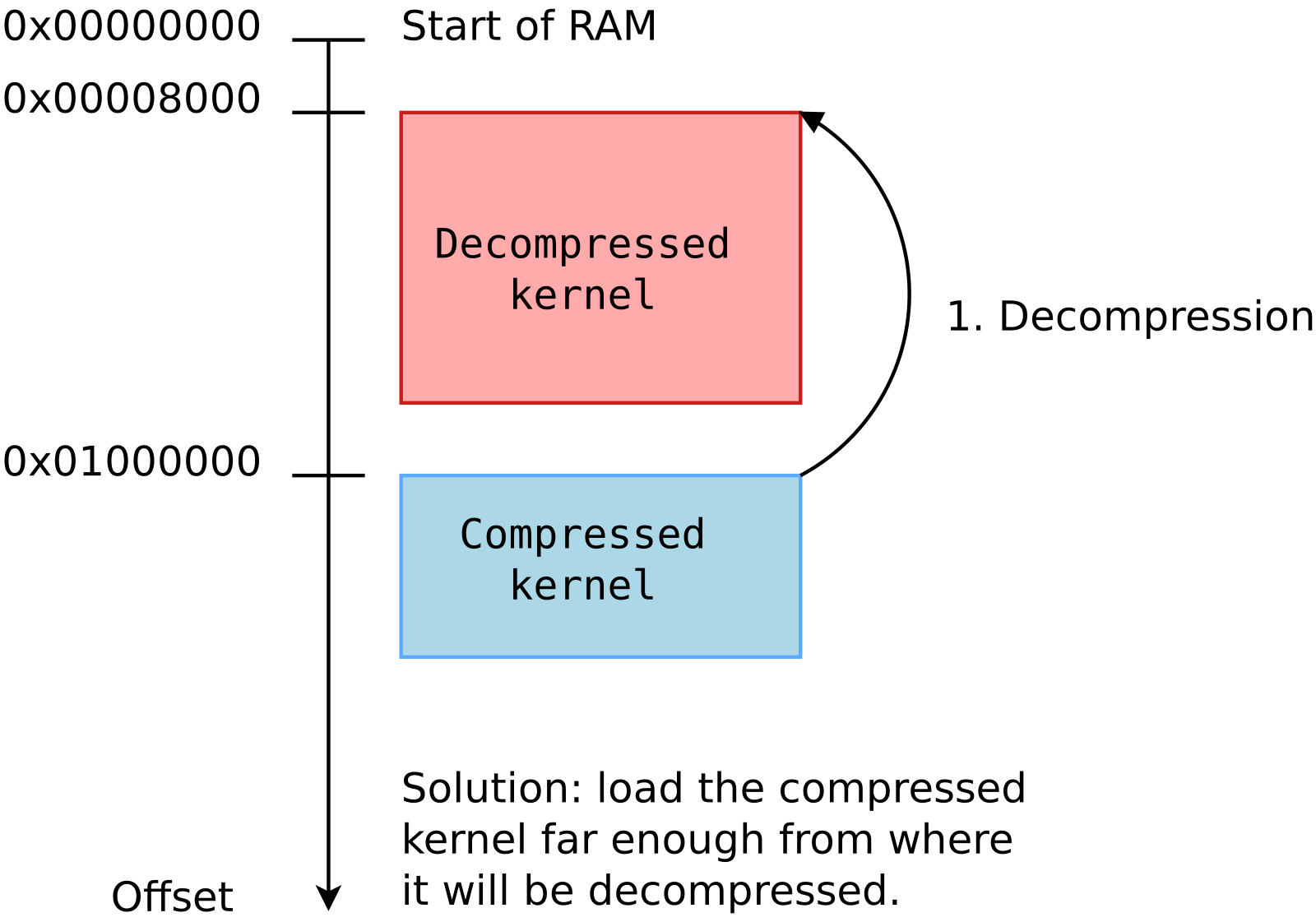
At least on ARM32, there seems to be many working addresses where the compressed kernel can be loaded in RAM. For example, one can load the compressed kernel at offset 0x1000000 (16 MB) from the start of RAM, and the Device Tree Blog (DTB) at offset 0x2000000 (32 MB). Whatever this loading address, the kernel is then decompressed at offset 0x8000 from the start of RAM, as explained this the famous How the ARM32 Linux kernel decompresses article from Linus Walleij.
There is a potential issue with the loading address of the compressed kernel, as explained in the article too. If the compressed kernel is loaded too close to the beginning of RAM, where the kernel must be decompressed, there will be an overlap between the two. The decompressed kernel will overwrite the compressed one, potentially breaking the decompression process.
As you see in the above diagram, when this happens, the bootstrap code in the compressed kernel will first copy the compressed image to a location that’s far enough to guarantee that the decompressed kernel won’t overlap it. However, this extra step in the boot process has a cost.
Measuring boot time impact
In the context of updating our materials for our upcoming Embedded Linux Boot Time Optimization course in June, we measured this additional time on the STM32MP157A-DK1 Discovery Kit from STMicroelectronics, with a dual-core ARM Cortex-A7 CPU running at 650 MHz.
0xc0000000 is exactly the beginning of RAM! We are therefore in the overlap situation.
We used grabserial from Tim Bird to measure the time between Starting kernel in U-Boot and when the compressed kernel starts executing (Booting Linux on physical CPU 0x0):
...
[4.451996 0.000124] Starting kernel ...
[0.001838 0.001838]
[2.439980 2.438142] [    0.000000] Booting Linux on physical CPU 0x0
...
On a series of 5 identical tests, we obtained an average time of 2,440 ms, with a standard deviation of 0.4 ms.
Then, we measured the optimum case, in which the compressed kernel is loaded far enough from the beginning of RAM so that no overlap is possible:
On a series of 5 identical tests, we obtained an average time of 2,333 ms, with a standard deviation of 0.7 ms.
The new average is 107 ms smaller, which you are likely to consider as a worthy reduction, if you have experience with boot time reduction projects.
What to remember
In your embedded projects, if you are using a compressed kernel, make sure it is loaded far enough from the beginning of RAM, leaving enough space for the decompressed kernel to fit in between. Otherwise, your system will still be able to boot, but depending on the speed of your CPU and storage, it will be slower, from a few tens to a few hundreds of milliseconds.
We checked the How to optimize the boot time page on the STM32 wiki, and it recommends optimum loading addresses: 0xc2000000 for the kernel and 0xc4000000 for the device tree. This way, the upper limit for the decompressed kernel is 32 MB, which is more than enough.
If you are directly using an uncompressed kernel, which is more rare, you should also make sure that it is loaded at an optimum location, so that there is no need to move it before starting it.
Before we get started in this blog post, it is important to mention that it is not meant to be a full introduction to programming applications with Qt5. This would require much more than a blog post, and the Qt web site has extensive documentation.
Also, we want to make it clear that Bootlin’s core expertise is in low-level embedded Linux development, not in Qt application development. Therefore, our example application may not show the best practices in terms of Qt development. We welcome comments and suggestions from our readers to improve the example used in this blog post.
Reading sensor data
As we’ve seen in a previous article, the sensor data is available by reading the following files:
/sys/bus/iio/devices/iio:device2/in_temp_input for the temperature
/sys/bus/iio/devices/iio:device2/in_pressure_input for the pressure
/sys/bus/iio/devices/iio:device2/in_humidityrelative_input for the humidity
So what we will do is writing a new class called DataProvider, which will read those files once per second, and emit a signal with the 3 values every second. Slots and signals is a fundamental mechanism in Qt, which allows to connect emitters of events to receivers for those events. In our case, the DataProvider class will emit a signal when new sensor values are read, while another class in charge of the graphical UI will receive those signals.
At this step, we don’t yet have a graphical UI, so we’ll simply add a few debugging messages in the DataProvider to make sure it works as expected.
Let’s start by adding a data-provider.h file to our project:
It creates a very simple class than inherits from QObject, with:
A constructor
A private slot handleTimer which will be used internally by the class QTimer’s instance to notify that a timer has expired. This is what will allow us to poll the sensor values every second.
A valueChanged signal, which will be emitted by the class every time new sensor values are available.
Then, the implementation of this class in data-provider.cpp is fairly straight-forward:
The constructor of the class connects the QTimer::timeout signal of the QTimer to this class handlerTimer slot, sets the timer interval to 1000 milliseconds, and starts the timer. This is what will ensure the handleTimer method gets called every second.
In the handleTimer method, we open the 3 files in sysfs, read their value and convert them to meaningful units: the temperature in Celcius, the pressure in hPA, and the humidity in percent. We then print a debugging message and emit the signal with the three values.
With this in place, we need to make sure those two files are properly taken into account by our project, by changing the .pro file as follows:
With this, you can now build and run the application, and you should see every second the debugging message showing the temperature, pressure and humidity values:
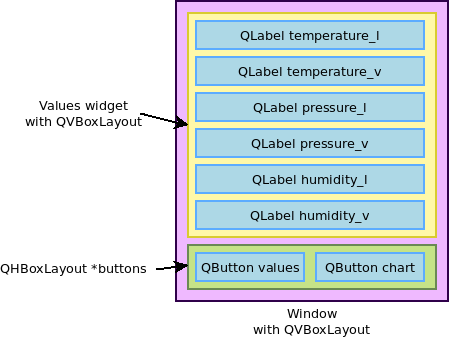
We now want to display the sensor data. For this, we'll create a UI with two panels, one to display the numeric value of the temperature, humidity and pressure, and another panel with a chart of the temperature. At the bottom of the screen, two buttons Values and Chart will allow to switch between both panels.
So, we'll create a Window class to encapsulate the overall window layout and behavior, and a Values class providing the widget showing the 3 values. We'll leave the chart implementation to the next section. To help you follow the code in this section, here is a diagram that shows the different widgets and how they will be grouped together in our user interface:
Let's start by implementing the Values widget, which will be used to show the 3 numeric values, one below each other. The values.h file will look like this:
#ifndef VALUES_H
#define VALUES_H

#include <QWidget>

class QLabel;

class Values : public QWidget
{
    Q_OBJECT

public:
    Values();

public slots:
    void handleValueChanged(float temp, float pressure, float humidity);

private:
    QLabel *temperature_v;
    QLabel *pressure_v;
    QLabel *humidity_v;
};

#endif /* VALUES_H */
So it has a simple constructor, a slot to be notified of new values available, and 3 text labels to display the 3 values. The implementation in values.cpp is:
// SPDX-License-Identifier: MIT
#include <QtWidgets>
#include "values.h"

Values::Values()
{
    QVBoxLayout *layout = new QVBoxLayout;

    QLabel *temperature_l = new QLabel(tr("Temperature (°C)"));
    QLabel *pressure_l = new QLabel(tr("Pressure (hPa)"));
    QLabel *humidity_l = new QLabel(tr("Humidity (%)"));

    temperature_v = new QLabel();
    pressure_v = new QLabel();
    humidity_v = new QLabel();

    QFont f = temperature_v->font();
    f.setPointSize(28);
    f.setBold(true);
    temperature_v->setFont(f);
    pressure_v->setFont(f);
    humidity_v->setFont(f);
    temperature_v->setAlignment(Qt::AlignRight | Qt::AlignVCenter);
    pressure_v->setAlignment(Qt::AlignRight | Qt::AlignVCenter);
    humidity_v->setAlignment(Qt::AlignRight | Qt::AlignVCenter);

    layout->addWidget(temperature_l);
    layout->addWidget(temperature_v);
    layout->addWidget(pressure_l);
    layout->addWidget(pressure_v);
    layout->addWidget(humidity_l);
    layout->addWidget(humidity_v);

    setLayout(layout);
}

void Values::handleValueChanged(float temp, float pressure, float humidity)
{
    temperature_v->setText(QString::number(temp, 'f', 2));
    pressure_v->setText(QString::number(pressure, 'f', 1));
    humidity_v->setText(QString::number(humidity, 'f', 1));
}
The constructor creates 3 text labels for the legends ("Temperature (°C)", "Pressure (hPA)" and "Humidity (%)"), then instantiates the 3 text labels for the values themselves. It sets up the font and text alignment properties for those labels, and then adds all widgets in a QVBoxLayout so that they all appear vertically below each other.
The handleValueChanged slot simply updates the text labels contents with the new sensor values, doing the proper text formatting on the way.
With the Values class implemented, we can now implement the main Window class. The window.h will contain:
#ifndef WINDOW_H
#define WINDOW_H

#include <QWidget>

class Values;

class Window : public QWidget
{
    Q_OBJECT

public slots:
    void handleValueChanged(float temp, float pressure, float humidity);

public:
    Window();

private:
    Values *values;
};

#endif
Beyond a simple constructor, it has a slot to receive new sensor values, and a reference to a Values widget instance.
The constructor creates a horizontal layout QHBoxLayout with two buttons: Values and Chart. Those will be used in the next section to switch between the Values panel and the Chart panel. For now, they don't do anything.
Then, the constructor adds the Value widget, and the horizontal layout box with the buttons into a vertical box layout, assigns the main window layout and defines the window title.
The handleValueChanged slot implementation just forwards the call to the Values::handleValueChanged method.
Now, obviously main.cpp needs to be changed: instead of creating a button, we'll create our window, and do a bit of additional setup:
So, not only we create the Window, but more importantly, we connect the valueChanged signal of DataProvider to the handleValueChanged slot of Window. We define the window size (which is fixed, to match the STM32MP15 Discovery board panel) and set the background color of the application.
Obviously, the qt-sensor-demo.pro file needs to be adjusted to build our new files. It now looks like this:
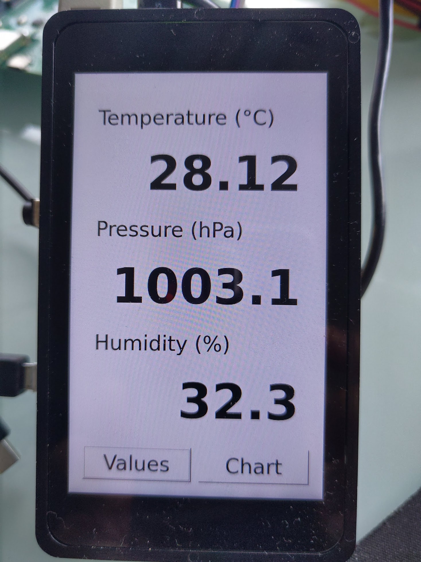
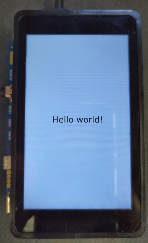
With this done, we can run the Qt5 application on our target, and see:
Graphing the temperature
The final part of developing our application is to implement a graph showing the evolution of temperature over time. For this, we are going to use the very convenient Qt Charts module, which is available in a separate Qt module from the base of Qt.
To implement the graph widget itself, we'll create a new Chart class:
#ifndef CHART_H
#define CHART_H

#include <QtCharts/QChart>

QT_CHARTS_BEGIN_NAMESPACE
class QSplineSeries;
class QValueAxis;
QT_CHARTS_END_NAMESPACE

QT_CHARTS_USE_NAMESPACE

class Chart: public QChart
{
    Q_OBJECT

public:
    Chart(QGraphicsItem *parent = 0, Qt::WindowFlags wFlags = 0);

public slots:
    void handleValueChanged(float temp, float pressure, float humidity);

private:
    QSplineSeries *m_series;
    QStringList m_titles;
    QValueAxis *m_axisX;
    QValueAxis *m_axisY;
    int xpos;
};

#endif /* CHART_H */
This class inherits from the QChart class provided by Qt. It provides a constructor and destructor, a slot that allows to receive notification of new sensor values, and it has a number of private variables to manage the chart itself.
Let's go through the implementation of this class now:
The constructor simply sets up the QChart we inherit from: defining the axis, their range, the pen width and color, etc. On the X axis (time), we are going to show 60 measurements, and since our handleValueChanged slot is going to be called every second, it means our graph will show the last 60 seconds of temperature measurement. On the Y axis (temperature), we can show temperatures from 0°C to 50°C. Of course, this is all very hardcoded in this example, for simplicity.
The handleValueChanged slot appends the new temperature value to the graph, and then updates the area displayed by the graph so that always the last 60 seconds are visible.
Now, we need to integrate this to our existing Window class, so that we can display the chart, and switch between the numeric values and the chart. First, we need to do some changes in window.h, and below we'll show only the diff to make the differences very clear:
So, we're defining two private slots that will be used for the two buttons that allow to switch between the numeric values and the chart, and then we add two variables, one for the chart itself, and one for the QChartView (which basically renders the graph into a widget).
So, in the constructor we are connecting the clicked signals of the two buttons to their respective slots. We create the Chart object, and then the QChartView to render the graph. We add the latter as an additional widget in the QVBoxLayout, and we hide it.
The existing handleValueChanged slot is modified to also update the Chart object with the new sensor values.
Finally, the new chartButtonClicked and valuesButtonClicked slots implement the logic that is executed when the buttons are pressed. We simply hide or show the appropriate widget to display either the numeric values or the chart. There is probably a nicer way to achieve this in Qt, but this was good enough for our example.
Now that the source code is in place, we of course need to adjust the build logic in qt-sensor-demo.pro:
Besides the obvious addition of the chart.cpp and chart.h file, the other important addition is charts to the QT variable. This tells qmake that our application is using the Qt Charts, and that we therefore need to link against the appropriate libraries.
Building the application
At this point, if you try to build the application, it will fail because QtCharts has not been built as part of our Buildroot configuration. In order to address this, run Buildroot's make menuconfig, enable the BR2_PACKAGE_QT5CHARTS option (in Target packages -> Graphic libraries and applications -> Qt5 -> qt5charts).
Then, run the Buildroot build with make, and reflash the resulting SD card image.
Now, you can build again your application, either with Qt Creator if you've been using Qt Creator, or manually. If you build it manually, you'll have to run qmake again to regenerate the Makefile, and then build with make.
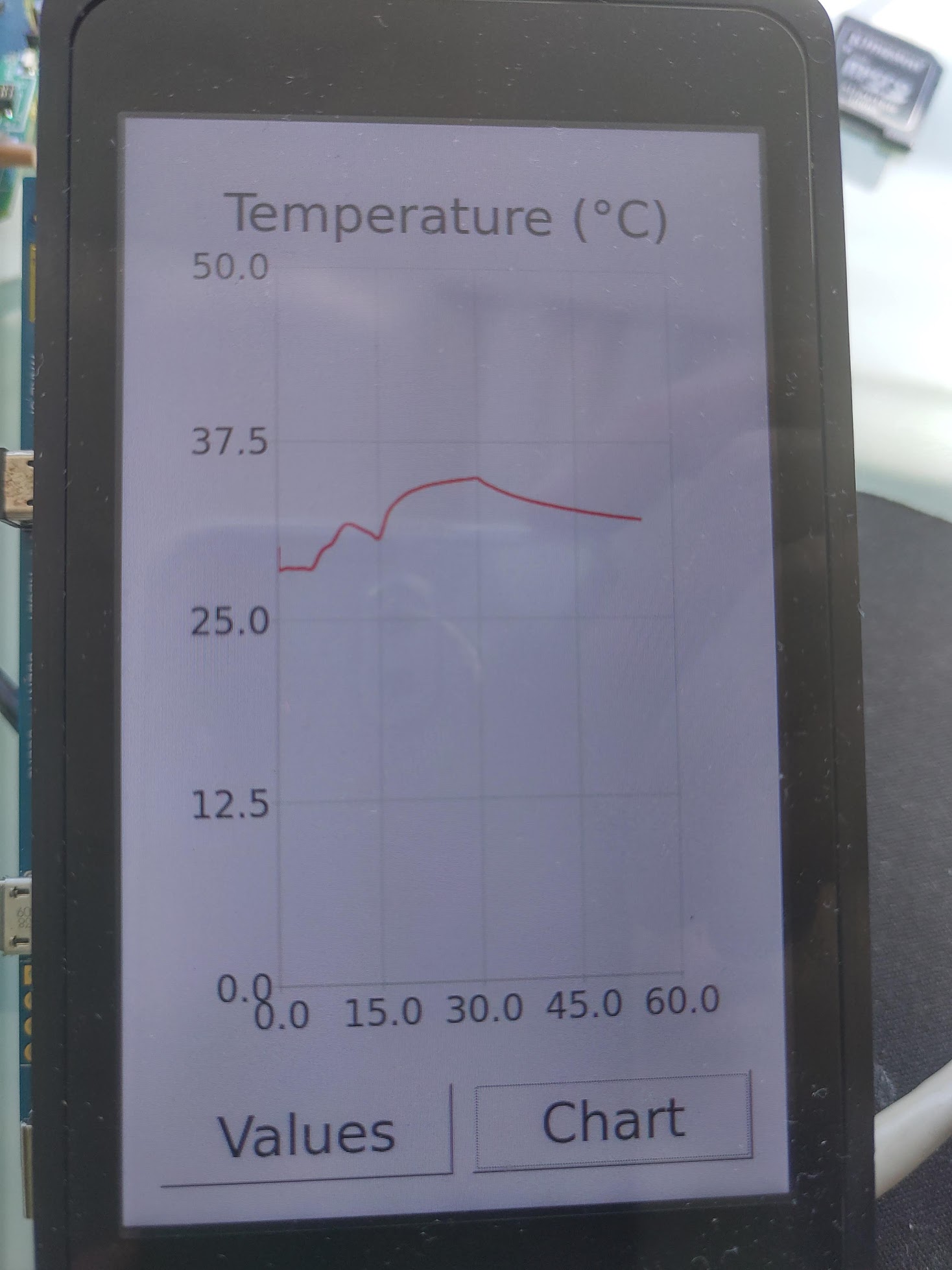
When you run the application on the target, the GUI will display the same numeric values as before, but now if you press the Chart button, it will show something like:
Adjusting the Buildroot package
We have for now been building this application manually, but as explained in our previous blog post, we really want Buildroot to be able to build our complete system, including our application. For this reason, we had created a qt-sensor-demo package, which gets our application source code, configures it with qmake, builds it and installs it.
However, with the new use of Qt Charts, our qt-sensor-demo package needs a few adjustements:
The Config.in file needs an additional select BR2_PACKAGE_QT5CHARTS, to make sure Qt Charts are enabled in the Buildroot configuration
The qt-sensor-demo.mk file needs an additional qt5charts in the QT_SENSOR_DEMO_DEPENDENCIES variable to make sure the qt5charts package gets built before qt-sensor-demo
With this in place, you can run:
make qt-sensor-demo-rebuild
make
And you have an SD card image that includes our application!
Starting the application automatically at boot time
The next and almost final step for this blog post is to get our application automatically started at boot time. We can simply add a small shell script on the target in /etc/init.d/: the default Buildroot configuration for the init system will execute all scripts named Ssomething in /etc/init.d/. We'll add a file named package/qt-sensor-demo/S99qt-sensor-demo with these contents:
#!/bin/sh

DAEMON="qt-sensor-demo"
DAEMON_ARGS="-platform linuxfb"
PIDFILE="/var/run/qt-sensor-demo.pid"

start() {
	printf 'Starting %s: ' "$DAEMON"
	start-stop-daemon -b -m -S -q -p "$PIDFILE" -x "/usr/bin/$DAEMON" -- $DAEMON_ARGS
	status=$?
	if [ "$status" -eq 0 ]; then
		echo "OK"
	else
		echo "FAIL"
	fi
	return "$status"
}

stop () {
	printf 'Stopping %s: ' "$DAEMON"
	start-stop-daemon -K -q -p "$PIDFILE"
	status=$?
	if [ "$status" -eq 0 ]; then
		rm -f "$PIDFILE"
		echo "OK"
	else
		echo "FAIL"
	fi
	return "$status"
}

restart () {
	stop
	sleep 1
	start
}

case "$1" in
        start|stop|restart)
		"$1";;
	reload)
		# Restart, since there is no true "reload" feature.
		restart;;
        *)
                echo "Usage: $0 {start|stop|restart|reload}"
                exit 1
esac
This is the canonical init script used in Buildroot to start system daemons and services, and is modeled after the one in package/busybox/S01syslogd. It uses the start-stop-daemon program to start our application in the background.
Then, to get this init script installed, we need to adjust package/qt-sensor-demo/qt-sensor-demo.mk with the following additional lines:
This ensures that the init script gets installed in /etc/init.d/S99qt-sensor-demo as part of the build process of our qt-sensor-demo package. Note that an init script works fine if you're using the Busybox init implementation or the sysvinit init implementation (we're using the default Buildroot setup here, which uses the Busybox init implementation). If you want to use systemd as an init implementation, then a different setup is necessary.
With this done, you simply need to reinstall the application and regenerate the SD card image
$ make qt-sensor-demo-reinstall
$ make
You can now test your SD card image on you board, and you should see the application being started automatically, with the following messages at boot time
Starting dropbear sshd: OK
Starting qt-sensor-demo: OK

Welcome to Buildroot
Avoid unnecessary logging on the display panel
In our current setup, the kernel messages are being sent to both the serial port and the framebuffer console, which means they appear on the display panel. This is not very pretty, and we would like the display to remain black until the application starts, while keeping the kernel messages on the serial port for debugging purposes. Also, we would like the framebuffer console text cursor to not be displayed, to really have a fully black screen. To achieve this we will add two arguments on the Linux kernel command line:
console=ttySTM0,115200, which will tell the Linux kernel to only use the serial port as the console, and not all registered consoles, which would include the framebuffer console. This option will make sure the kernel messages are not displayed on the screen.
vt.global_cursor_default=0, which will tell the Linux kernel to not display any cursor on the framebuffer console.
So, to add those options, we simply modify board/stmicroelectronics/stm32mp157-dk/overlay/boot/extlinux/extlinux.conf in Buildroot as follows:
Of course, rebuild the SD card image with make, reflash and test the result on your STM32MP1 platform.
Conclusion
In this blog post, we have seen how to write a real (but admittedly very simple) Qt application, how to make it read and display sensor data, and how to integrate this application so that it gets started at boot time.
You can find the Buildroot changes corresponding to this blog post in the 2019.02/stm32mp157-dk-blog-5 branch of our repository. The qt-sensor-demo application code can be found in the blog-5 branch of this application Git repository.
Stay tuned for our next blog post about factory flashing and OTA update!
We’ll call our application qt-sensor-demo, so create a directory with this name, outside of Buildroot. It’s important to not mix up your application code with your build system: you could very well decide to use another build system one day, while keeping your application code. To keep things simple, create this qt-sensor-demo side-by-side with Buildroot, as this will be important for a future step in this blog post.
In this directory, create a main.cpp file with the following code:
It should be fairly straight-forward to understand that this program creates a QApplication object, a push button with the Hello world! label, sets the button size to 100 by 30 pixels, shows the button, and enters the application event loop. It is obviously a very basic application, because it doesn’t do anything useful, but that’s good enough as a starting point.
Now, we need to build this application. Building Qt applications by hand is definitely not reasonable, as Qt may need to run several tools on the source code before it gets built, and requires a number of compiler and linker flags. So, we won’t write a Makefile by hand, but instead use a build tool that generates the Makefile for us. We have a number of options here:
In this blog post, we’ll simply stick to qmake, which is good enough for a number of Qt-based applications. qmake takes as input one or several .pro files describing the project, and uses that to generate Makefiles (on Linux systems).
In our case, the qt-sensor-demo.pro file will be as simple as:
QT += widgets
SOURCES = main.cpp
Building our application
We have two ways to build our application:
Manually outside of Buildroot. In this case, we’ll use the Buildroot-provided compiler and tools, but we will trigger the build of our application separately from the Buildroot build.
Using Buildroot. In this case, our application would have a corresponding Buildroot package, that would automate building the application as part of the complete system build process.
Ultimately, we definitely want to have a Buildroot package for our application, to make sure the entire build is fully automated. However, during the active development of the application, it may be useful to build it manually outside of Buildroot, so we are going to see both solutions, which are not mutually exclusive: you can have a Buildroot package for your application, and still build it manually when you’re doing active development/debugging.
Building manually outside of Buildroot
To build manually, we simply need to first invoke Buildroot’s provided qmake:
/path/to/buildroot/output/host/bin/qmake
This will generate a Makefile, that we can use to build our application:
make
At this point, you should have:
$ ls
main.cpp  main.o  Makefile  qt-sensor-demo  qt-sensor-demo.pro
The qt-sensor-demo executable is compiled for ARM, and linked against the various libraries built by Buildroot.
Now, we need this executable on our STM32MP15 target. For now, we’ll simply add it to the SD card image:
cp qt-sensor-demo /path/to/buildroot/output/target/usr/bin/
cd /path/to/buildroot/
make
Hello World Qt application running on the STM32MP15 Discovery platformThis will copy the executable to the output/target folder, which contains the root filesystem produced by Buildroot. Then invoking Buildroot’s make will ensure that the root filesystem and SD card images get re-generated. Of course, beware that if you run a Buildroot make clean, all the contents of output/, including output/target/ get removed. So this technique is only suitable for temporary changes. This is fine since anyway as discussed above, ultimately we’ll have a proper Buildroot package to build our qt-sensor-demo application.
Reflash your SD card with the new image, and on the target, run the demo:
# qt-sensor-demo -platform linuxfb
Setting SSH for communication with the board
Regenerating the SD card image and reflashing the entire SD card every time we want to change our application is not going to be very efficient during the application development/debugging. So instead, we’ll set up networking communication with the board, and use SSH to transfer files. This will also be useful for Qt Creator, as it uses SFTP to deploy files to the target.
Let’s start by enabling a small SSH client/server, called Dropbear. Go in Buildroot menuconfig, and enable the BR2_PACKAGE_DROPBEAR option (in Target packages, Networking applications, dropbear). While Dropbear provides SSH access, it does not support SFTP which will be needed by Qt Creator, so we’ll also enable an SFTP server, gesftpserver. So, we’ll enable BR2_PACKAGE_GESFTPSERVER as well (in Target packages, Networking applications, gesftpserver).
Then, in order to log in through SSH as root, we must have a non-empty root password, so set BR2_TARGET_GENERIC_ROOT_PASSWD (in System configuration, Root password) to a value you like.
You can now exit menuconfig, as we have enabled all features we needed. Before restarting the build, we need to do one last thing: set up a network configuration file so that our STM32MP15 system configures an IP address. To do this, we’ll create a /etc/network/interfaces file, and add it to the root filesystem using the root filesystem overlay mechanism, which was presented in the first post of this series. So, in your Buildroot sources, just create a file board/stmicroelectronics/stm32mp157-dk/overlay/etc/network/interfaces, with the following contents:
auto lo
iface lo inet loopback

auto eth0
iface eth0 inet static
      address 192.168.42.2
      netmask 255.255.255.0
This will ensure the eth0 interface of our target gets configured with the 192.168.42.2 IP address. Of course, feel free to use a different IP address.
Then, run make in Buildroot, reflash your SD card, and boot your system. At boot time, you should see:
Starting dropbear sshd: OK
You can also run ip addr show dev eth0 to check the IP address of the eth0 interface:
2: eth0:  mtu 1500 qdisc mq qlen 1000
    link/ether 00:80:e1:42:4d:e3 brd ff:ff:ff:ff:ff:ff
    inet 192.168.42.2/24 scope global eth0
       valid_lft forever preferred_lft forever
    inet6 fe80::280:e1ff:fe42:4de3/64 scope link
       valid_lft forever preferred_lft forever
So the IPv4 address is properly set to 192.168.42.2, as expected.
Now, on your workstation, we need to configure the 192.168.42.1 static IP address so that you can connect to your board. It is very likely that the Linux system on your workstation is using NetworkManager. Let’s add a connection:
$ nmcli con add con-name buildroot-target type ethernet ifname enp57s0u1u3 ip4 192.168.42.1/24
Connection 'buildroot-target' (234e0d9a-5c4f-4eac-9277-c3587bbd370d) successfully added.
Make sure to replace enp57s0u1u by the name of your PC wired interface, to which the board is connected. We of course assume you have an Ethernet cable directly connecting your PC to the board.
Finally, enable the connection:
$ nmcli con up id buildroot-target
Connection successfully activated (D-Bus active path: /org/freedesktop/NetworkManager/ActiveConnection/10)
We can now ping our target:
$ ping 192.168.42.2
PING 192.168.42.2 (192.168.42.2) 56(84) bytes of data.
64 bytes from 192.168.42.2: icmp_seq=1 ttl=64 time=1.33 ms
Log-in over SSH:
$ ssh root@192.168.42.2
root@192.168.42.2's password:
# uname -a
Linux buildroot 4.19.26 #1 SMP PREEMPT Wed Aug 28 15:54:58 CEST 2019 armv7l GNU/Linux
# cat /etc/issue
Welcome to Buildroot
#
So, now we can make a change to our Qt5 application, for example changing the label of the button, recompile by running make in the application directory, and directly copy the application using scp, and run it over ssh:
Much nicer, we don’t have to reflash our SD card every time we want to test a change in our application!
Note that we could create a public/private key pair, with the public key on our target, and this way not have to enter our password every time we want to transfer a file or log-in to the target. Since this blog post is already very long, we’ll live that as an exercise for the reader, there are plenty of resources on the Web about this topic.
Setting up Qt Creator
Some people (such as your author) are happy with using a powerful text editor (such as Vim or Emacs) and a terminal to do their application development. But others are sometimes more comfortable with an integrated development environment (IDE). So in this section, we’ll see how to set up Qt Creator to write, build, deploy and debug a Qt5 application.
Installing Qt Creator
First of all, you’ll have to install Qt Creator, which you can do using the package management system of your distribution. On Fedora systems, this would be:
$ sudo dnf install qt-creator
On Debian/Ubuntu systems:
$ sudo apt install qtcreator
The following instructions have been written and tested against Qt Creator version 4.9.2.
Creating a kit
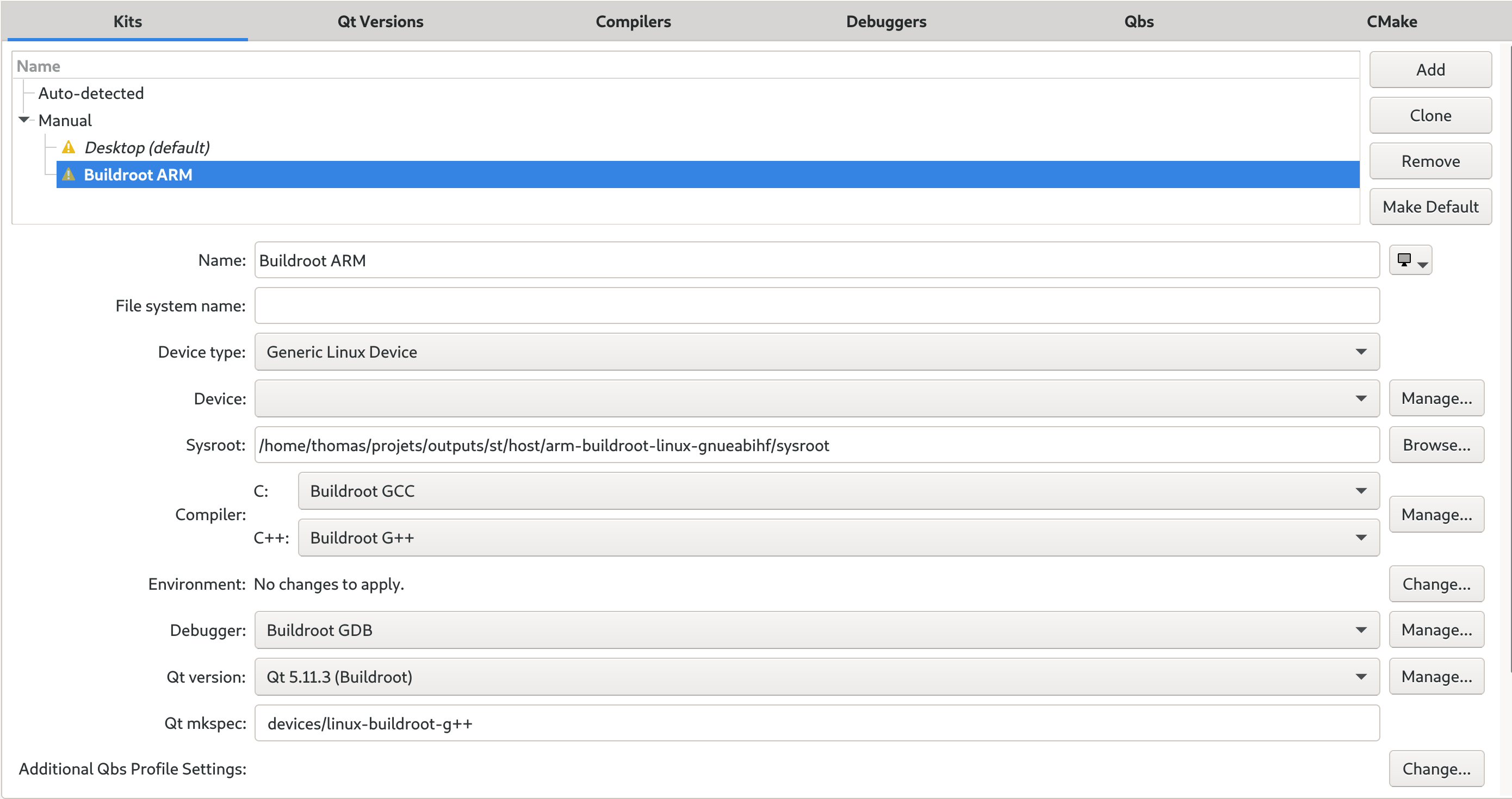
After starting Qt Creator, the first thing to do is to create a kit, which describes the cross-compiler and Qt installation provided by Buildroot. Go to Tools -> Options, and the first item should be Kits:
Click on Add, and fill in the different fields as follows:
Name: Buildroot ARM
Device type: Generic Linux Device
Sysroot: /path/to/buildroot/output/host/arm-buildroot-linux-gnueabihf/sysroot/. Of course, replace /path/to/buildroot/ with the appropriate path on your system.
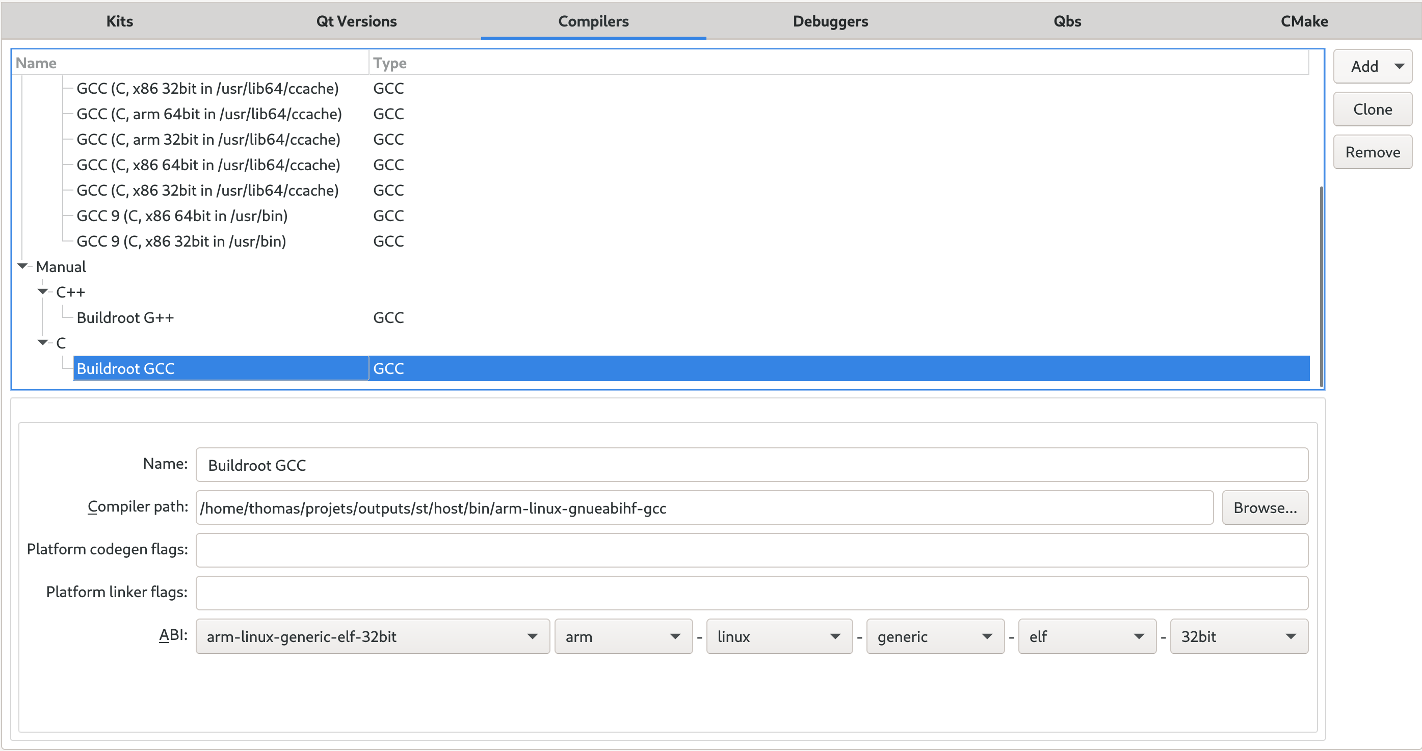
For the compiler, click on Manage, then in the Compiler panel:
Add one GCC C compiler, with the name Buildroot GCC and pointing to /path/to/buildroot/output/host/bin/arm-linux-gnueabihf-gcc
Add one GCC C++ compiler, with the name Buildroot G++ and pointing to /path/to/buildroot/output/host/bin/arm-linux-gnueabihf-g++
Back in the Kits panel, select Buildroot GCC and Buildroot G++ as the C and C++ compilers, respectively.
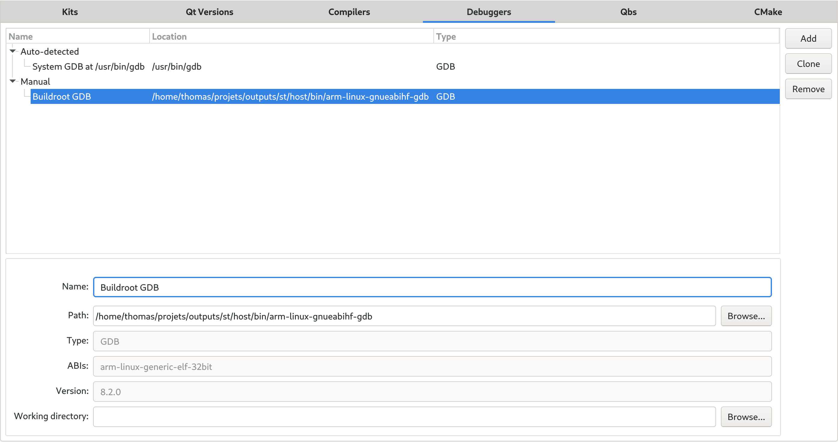
For the debugger, click on Manage, then in the debugger panel add one debugger named Buildroot GDB, and pointing to /path/to/buildroot/output/host/bin/arm-linux-gnueabihf-gdb. Back in the Kits panel, select Buildroot GDB as our debugger.
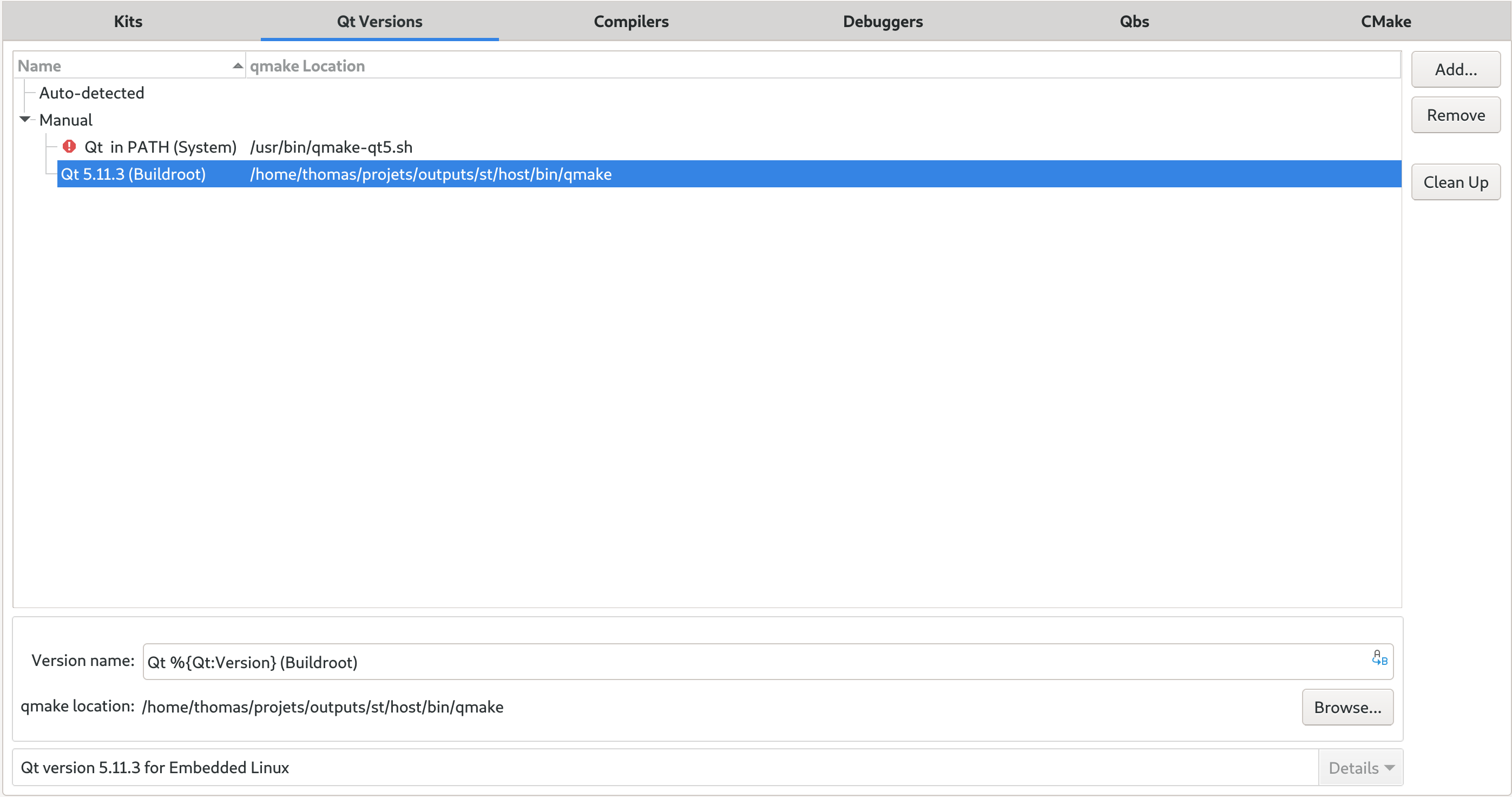
For the Qt version, click on Manage, then on Add, and point to the qmake binary in /path/to/buildroot/output/host/bin/. It will auto-detect that Buildroot has built Qt 5.11.3. You may want to adjust the version name from Qt %{Qt:Version} (host) to Qt %{Qt:Version} (Buildroot), as this Qt version is clearly not built for our host PC. Then back in the Kits panel, select this new Qt version.
For the Qt mkspec, enter devices/linux-buildroot-g++, which is the name of the mkspec configuration Buildroot generates.
You’ll find below screenshots of the various panels, with the details related to the Buildroot cross-compiler, cross-debugger and Qt installation:
Qt Creator Kits panel, filled in with the details of the Buildroot cross-compiler, cross-debugger and Qt installationQt Creator compiler panel, filled in with the details of the Buildroot C compilerQt Creator compiler panel, filled in with the details of the Buildroot C++ compilerQt Creator debugger panel, filled in with the details of the Buildroot cross-debuggerQt Creator Qt version panel, filled in with the details of the Buildroot Qt installation
We’re now done configuring a Kit!
Creating a device
In order to allow Qt Creator to deploy our application to the device, run it and debug it, we need to create a Device. Go again in Tools -> Options, and this time go to the Devices panel.
In the first window, select Generic Linux Device.
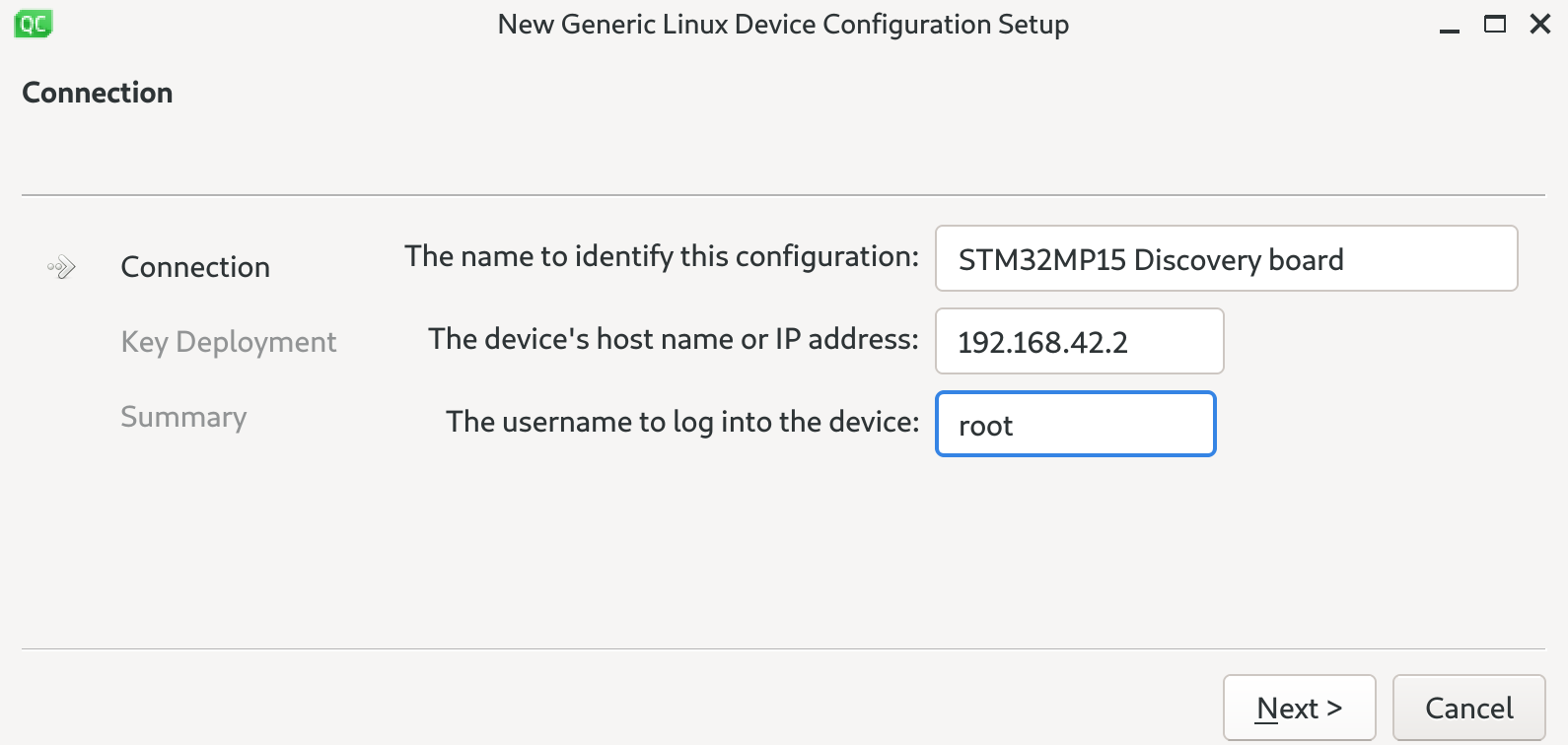
Then, for the device name, use STM32MP15 Discovery board for example, for the IP address, 192.168.42.2 and for the user, root, which should give:
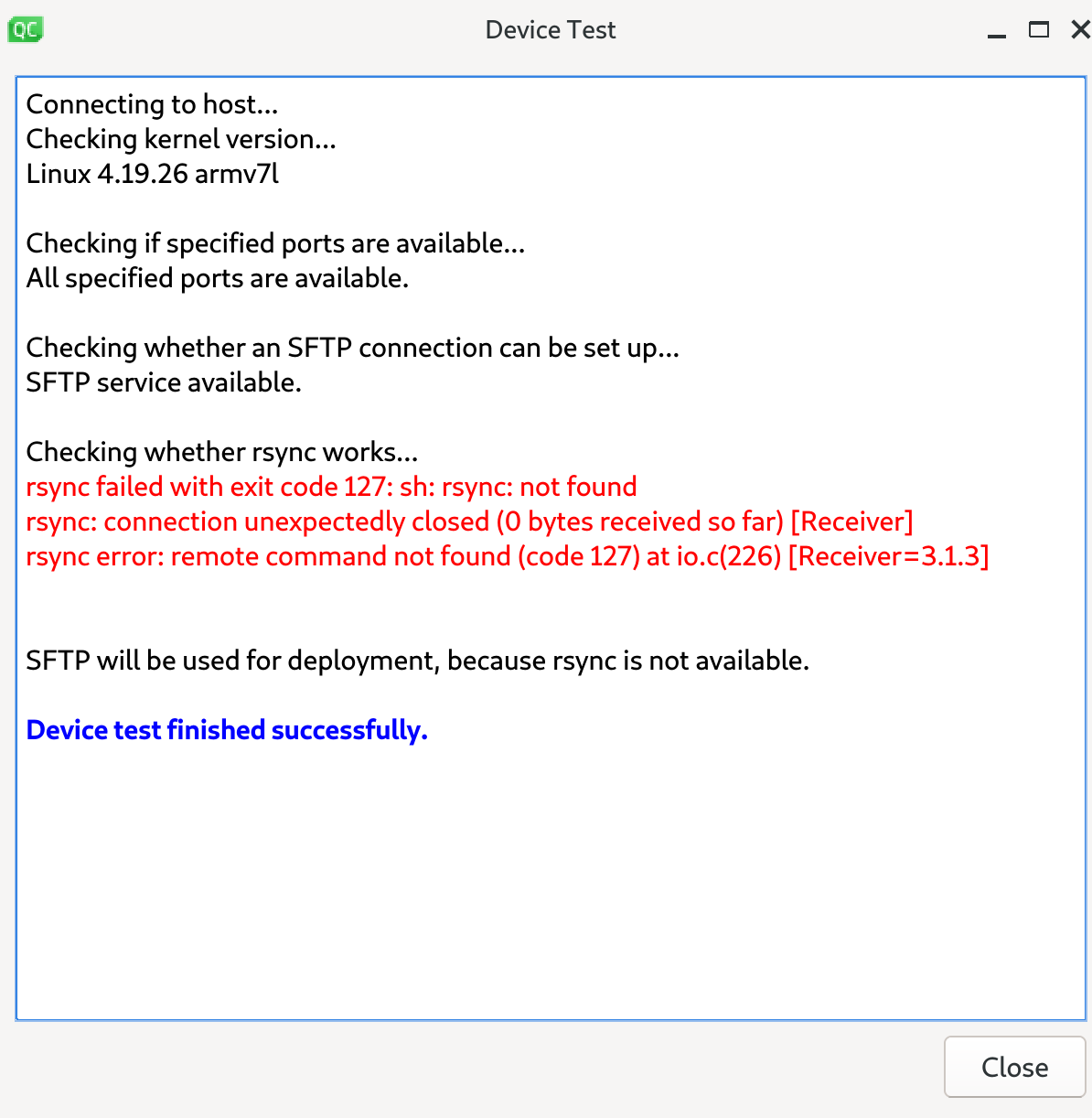
In the next step about Key deployment, simply skip to the next section, as we have not created a private/public key pair, as explained previously in this blog post. You can then finalize the device creation. Qt Creator will now test that it can communicate as expected with our device:
As you can see, it doesn’t find rsync on the target, because we have not installed it. It will use sftp instead, which is fine.
Back in the Device panel, you should see our device definition as follows:
Qt Creator device panel, filled in with the details of our STM32MP15 Discovery board
You can click on Open Remote Shell to directly open a shell over SSH to your target, or Show Running processes.
Our device is now set up correctly, time to create our first application!
Importing our project
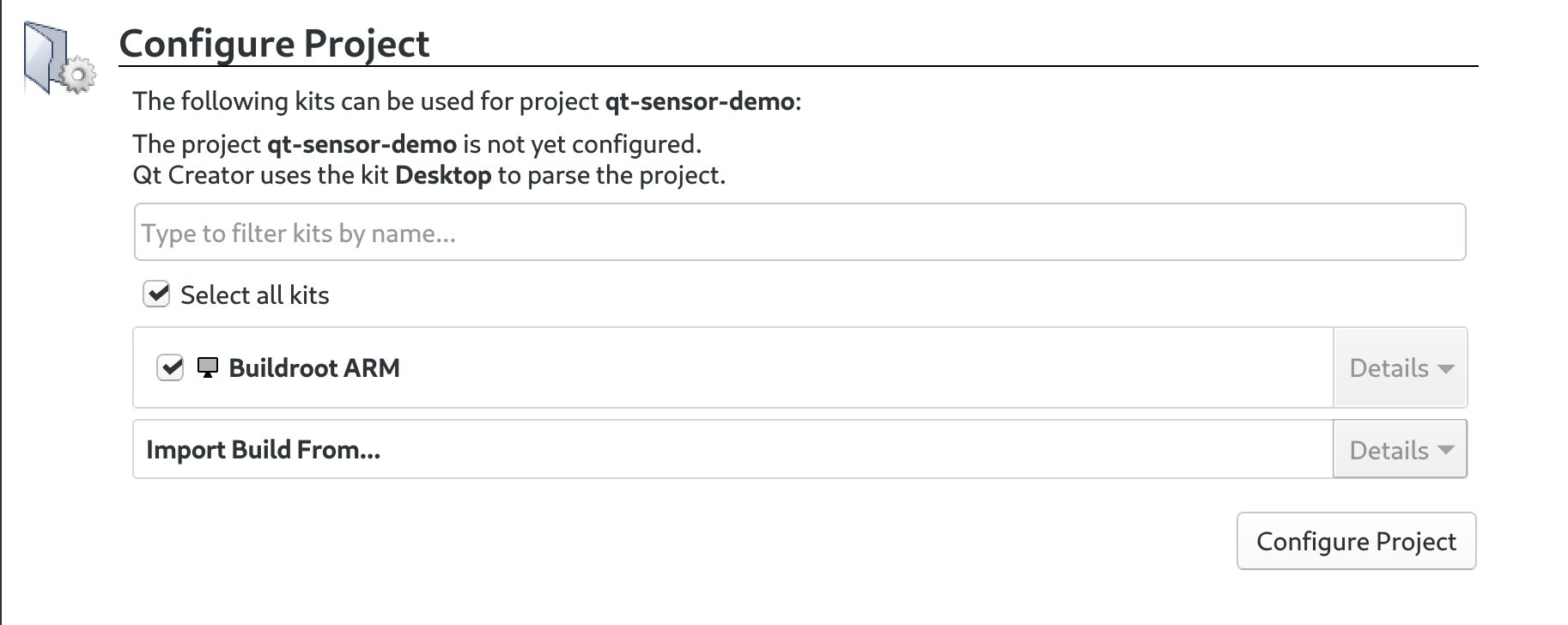
We now want to import our qt-sensor-demo project in Qt Creator. To do so, go in File -> Open File or Project, then browse to the directory containing our qt-sensor-demo application, and select both the main.cpp and qt-sensor-demo.pro files, and click Open. Qt Creator should now switch to a Configure project window, where it asks you to select the Kit to use for this project. Obviously, select the Buildroot ARM kit we have just created, and validate by clicking Configure Project:
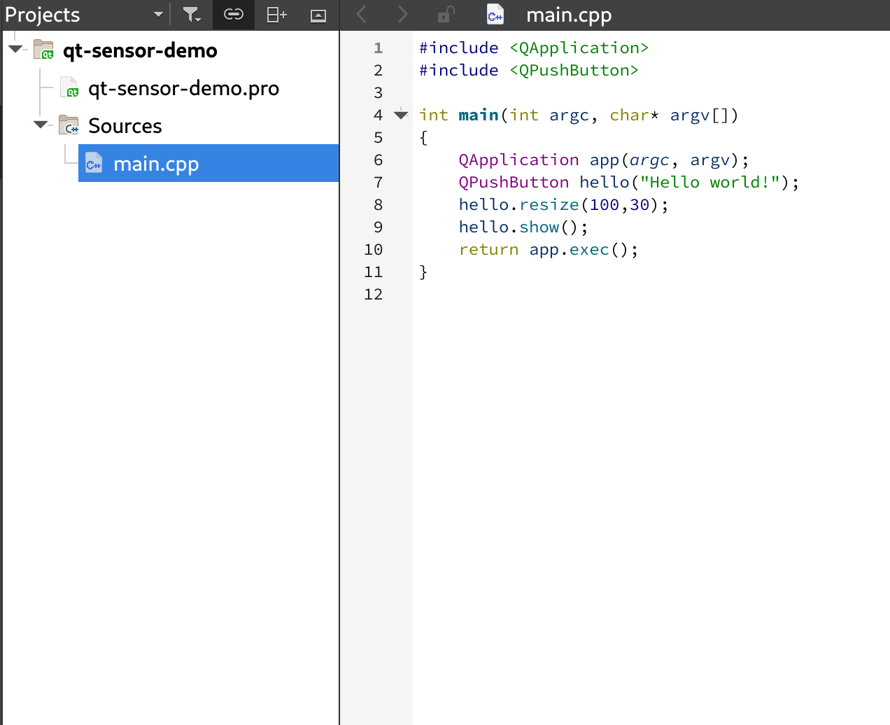
You should now see our project imported, with both of its files, and main.cpp is opened by default:
If we now use Build -> Build All, and then go in the Compile Output panel, we see:
13:11:58: Running steps for project qt-sensor-demo...
13:11:59: Starting: "/home/thomas/projets/outputs/st/host/bin/qmake" /home/thomas/qt-sensor-demo/qt-sensor-demo.pro -spec devices/linux-buildroot-g++ CONFIG+=debug CONFIG+=qml_debug
Info: creating stash file /home/thomas/build-qt-sensor-demo-Buildroot_ARM-Debug/.qmake.stash
13:11:59: The process "/home/thomas/projets/outputs/st/host/bin/qmake" exited normally.
13:11:59: Starting: "/usr/bin/make" -f /home/thomas/build-qt-sensor-demo-Buildroot_ARM-Debug/Makefile qmake_all
make: Nothing to be done for 'qmake_all'.
13:11:59: The process "/usr/bin/make" exited normally.
13:11:59: Starting: "/usr/bin/make" -j4
/home/thomas/projets/outputs/st/host/bin/arm-linux-gnueabihf-g++ -c -pipe -D_LARGEFILE_SOURCE -D_LARGEFILE64_SOURCE -D_FILE_OFFSET_BITS=64 -Os -Og --sysroot=/home/thomas/projets/outputs/st/host/arm-buildroot-linux-gnueabihf/sysroot -g -Wall -W -D_REENTRANT -fPIC -DQT_QML_DEBUG -DQT_WIDGETS_LIB -DQT_GUI_LIB -DQT_CORE_LIB -I../qt-sensor-demo -I. -I../projets/outputs/st/host/arm-buildroot-linux-gnueabihf/sysroot/usr/include/qt5 -I../projets/outputs/st/host/arm-buildroot-linux-gnueabihf/sysroot/usr/include/qt5/QtWidgets -I../projets/outputs/st/host/arm-buildroot-linux-gnueabihf/sysroot/usr/include/qt5/QtGui -I../projets/outputs/st/host/arm-buildroot-linux-gnueabihf/sysroot/usr/include/qt5/QtCore -I. -I../projets/outputs/st/host/mkspecs/devices/linux-buildroot-g++ -o main.o ../qt-sensor-demo/main.cpp
/home/thomas/projets/outputs/st/host/bin/arm-linux-gnueabihf-g++ --sysroot=/home/thomas/projets/outputs/st/host/arm-buildroot-linux-gnueabihf/sysroot -o qt-sensor-demo main.o   -lQt5Widgets -lQt5Gui -lQt5Core -lrt -ldl -latomic -lpthread
13:12:00: The process "/usr/bin/make" exited normally.
13:12:00: Elapsed time: 00:02.
So we see that it is invoking qmake from Buildroot, and then running make, which builds our application, with the appropriate cross-compiler provided by Buildroot!
The application has been built in /home/thomas/build-qt-sensor-demo-Buildroot_ARM-Debug, which contains:
-rw-rw-r-- 1 thomas thomas 620760 30 août  13:12 main.o
-rw-rw-r-- 1 thomas thomas  31522 30 août  13:11 Makefile
-rwxrwxr-x 1 thomas thomas 516504 30 août  13:12 qt-sensor-demo
Running the application on the target
In order for Qt to deploy our application on the target, we need to adjust our .pro file so that it has directives to install the application. We’ll simply make our .pro file look like this:
We invite you to read the relevant part of the Qt documentation to get details about the INSTALLS directive and the special target keyword.
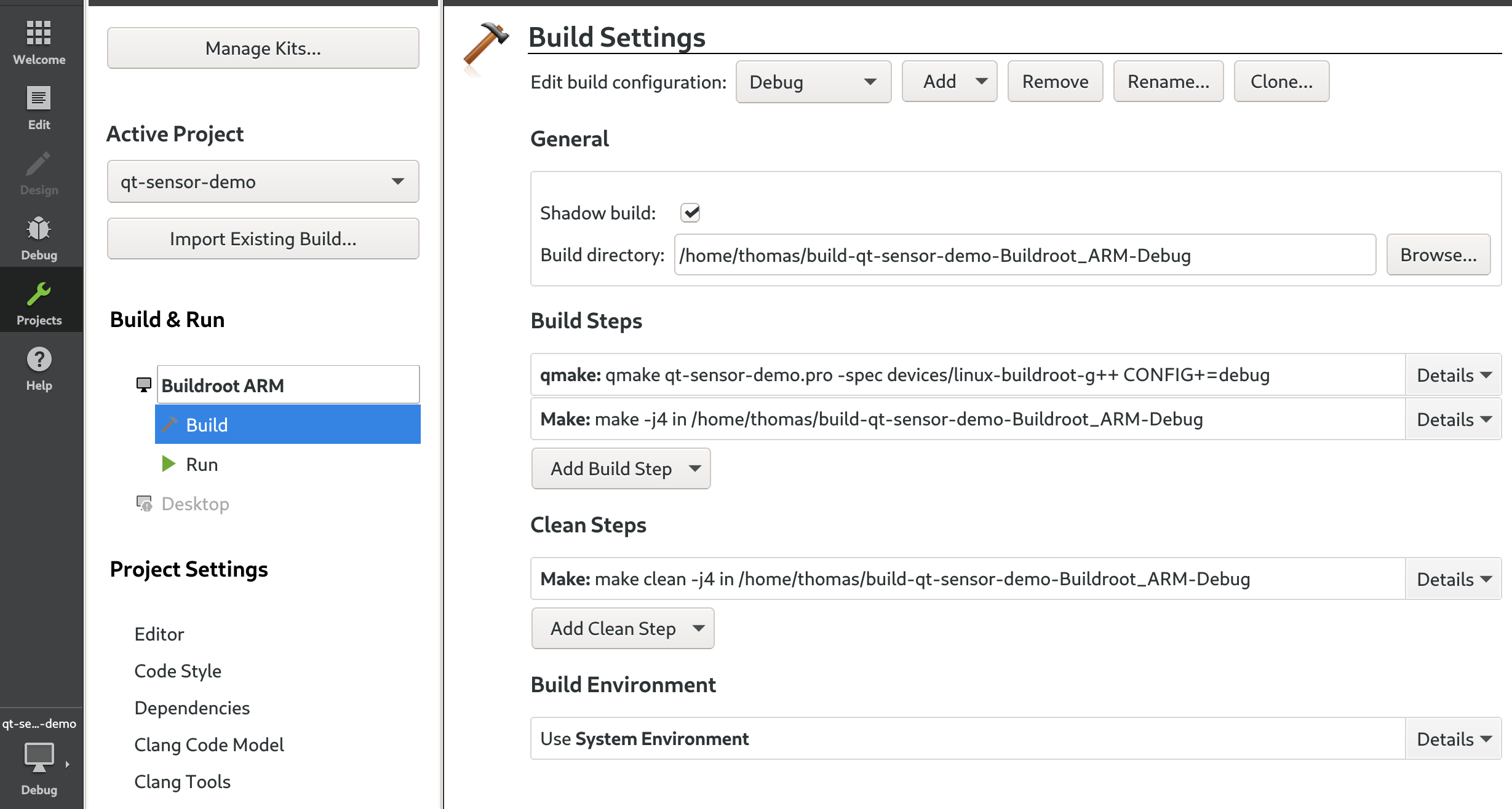
Before we can really deploy on your target, we need to adjust the Run configuration, so click on the Project icon in the left bar, which should bring you to:
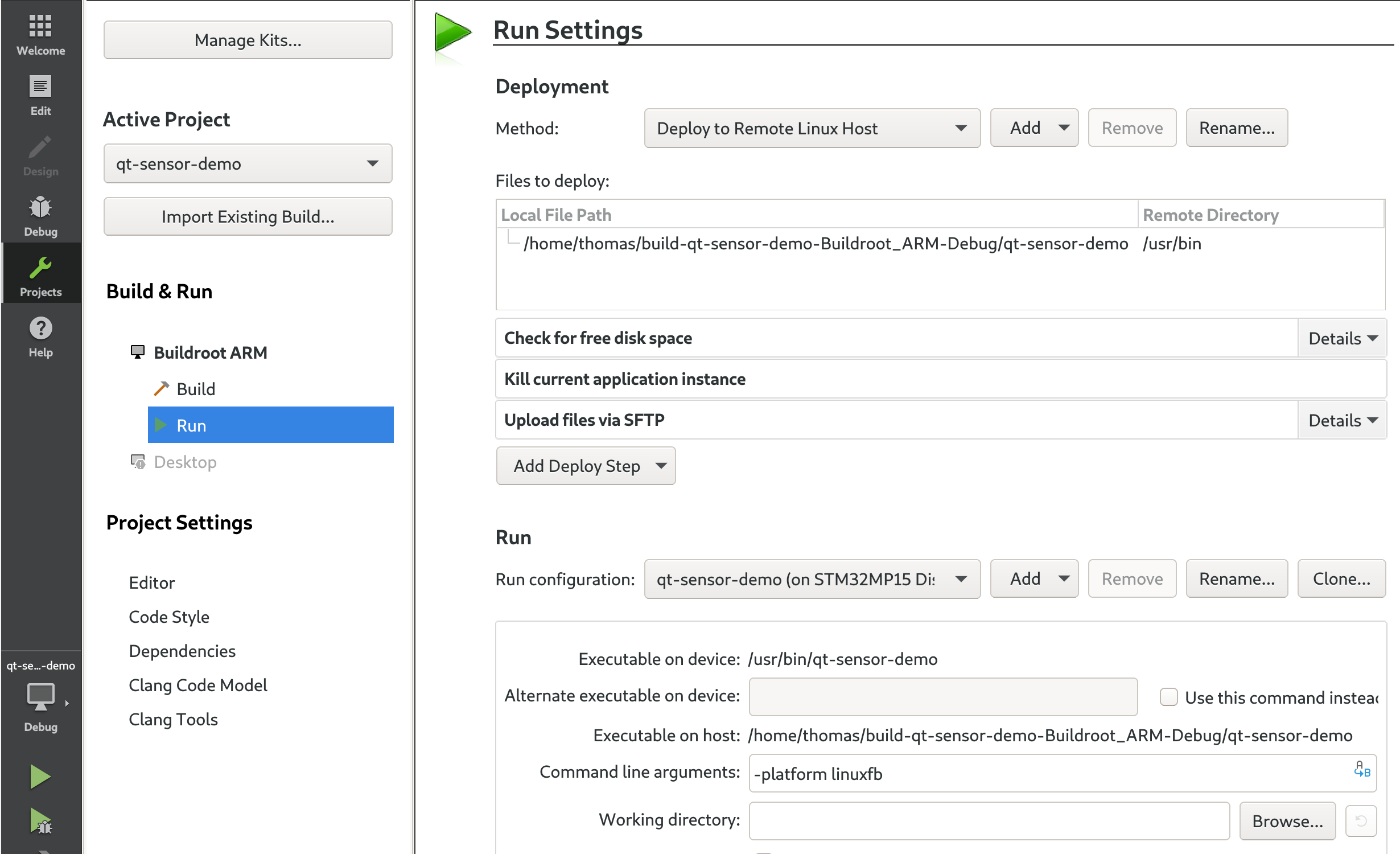
We’re seeing the Build settings, so click on Run to see the Run settings. Everything should already be auto-detected: we want to deploy qt-sensor-demo to /usr/bin on the target, the target is STM32MP15 Discovery board. The only thing we need to change is to set Command line arguments to -platform linuxfb. Your settings should then look like this:
Now, you can finally do Build -> Run. Qt Creator will prompt you for the root password of your target, and automatically deploy and run the application!
Just to test it, make a change to the QPushButton label, and do Build -> Run again. You’ll see the new version of your application running!
Debugging your application
The last part in setting up our development environment is to be able to debug our application from Qt Creator. This involves remote debugging, where the debugger runs on your workstation, while the program being debugged runs on a separate target. As part of the Kit definition done previously, we have already told Qt Creator where the cross debugger provided by Buildroot is.
Now, we need to have gdbserver on the target, which is the program with which the cross-debugger will communicate to control the execution of our application on the target. To achieve this, go to the Buildroot menuconfig, and enable the option BR2_TOOLCHAIN_EXTERNAL_GDB_SERVER_COPY, in Toolchain -> Copy gdb server to the Target. With this done, we now need to have Buildroot take this change into account. Unfortunately simply running make will not take this change into account (see here for more details). We could do a full clean rebuild of Buildroot (make clean all), but that would take quite some time, so we’ll ask Buildroot to only reinstall the toolchain package and regenerate the root filesystem image:
make toolchain-external-arm-arm-reinstall all
Reflash your SD card, and reboot the system. You should now have gdbserver available on the target:
# ls -l /usr/bin/gdbserver
-rwxr-xr-x    1 root     root        355924 Aug 29  2019 /usr/bin/gdbserver
We’ll now change a bit our program with some additional dummy code to play around with the debugger:
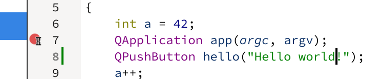
Place a breakpoint on the line QApplication app(argc, argv) by clicking to the left of this line, it should show a red dot, like this:
Then you can start debugging by clicking on the following button in the left bar:
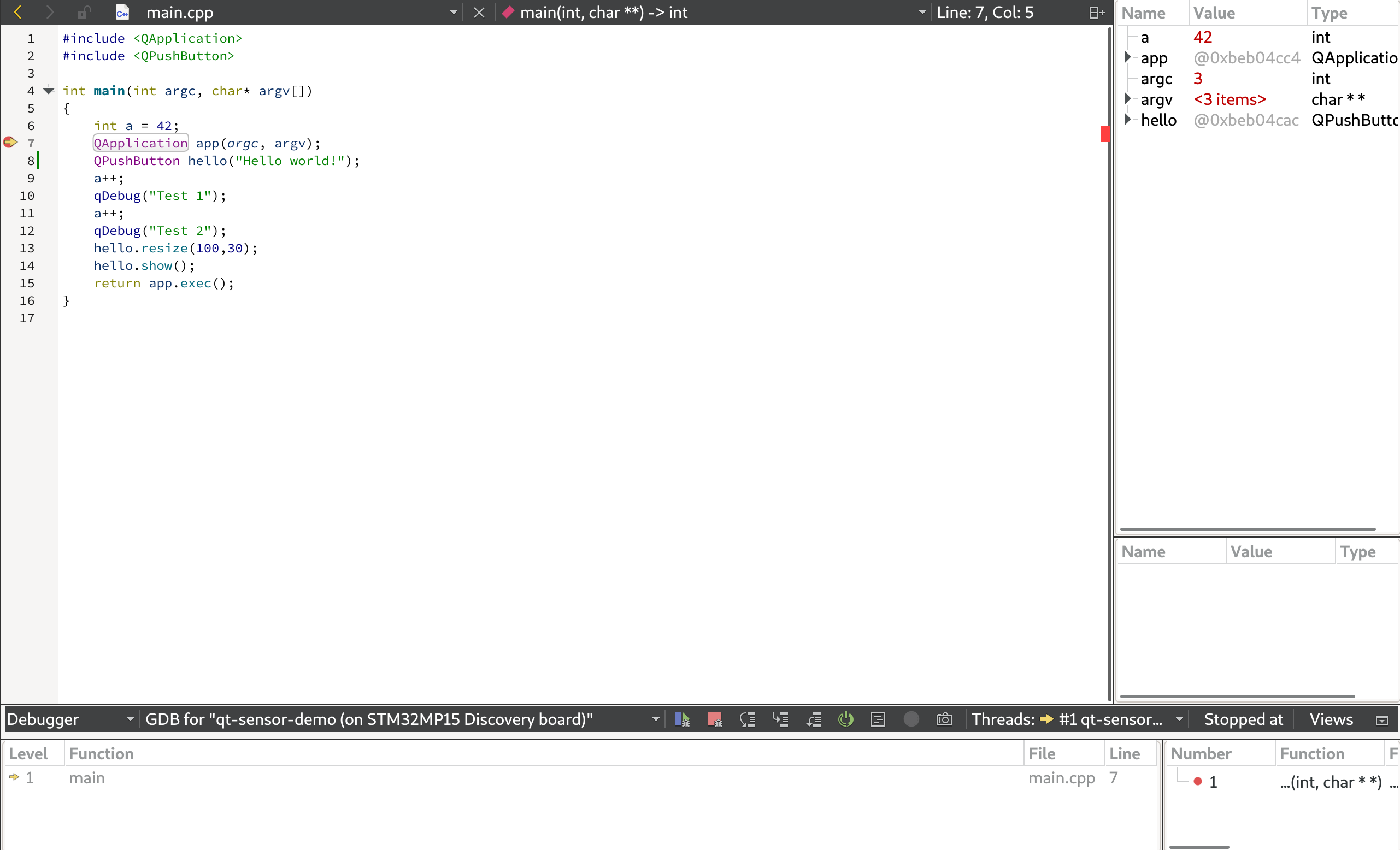
It will switch to the debug view, with the program stopped at our breakpoint:
At the bottom of the screen, click on Application Output so that we can see the stdout of the application running on the target. Now hit F10 to step through our code line by line. You should then see the value of the variable a updated in the top right panel, and the Test 1 and then Test 2 messages printed in the application output:
So, as expected, we are able to debug our application! This concludes the setup of Qt Creator, which allows us to very easily make a change to our application, build it, deploy it on the target and debug it.
Building using a Buildroot package
Before we conclude this article, we want to see how to integrate the build of our application with Buildroot. Indeed, building the application manually or through Qt Creator is perfectly fine during the active development of the application. But in the end, we want Buildroot to be able to build our complete system, including all the applications and libraries we have developed, in a fully automated and reproducible fashion.
To achieve this, in this section, we’ll create a Buildroot package for our qt-sensor-demo application. A package in Buildroot speak is a small set of metadata that tells Buildroot how to retrieve and build a particular piece of software.
To learn how to create a Buildroot package, we suggest you to read the relevant section of the Buildroot manual, or to read the slides of our Buildroot training course. The following steps will however guide you in the process of creating our qt-sensor-demo package.
First, in the Buildroot source tree, create a package/qt-sensor-demo/ directory. Then, create a file named package/qt-sensor-demo/Config.in, which describes one configuration option to be able to enable/disable this package from Buildroot’s menuconfig:
config BR2_PACKAGE_QT_SENSOR_DEMO
        bool "qt-sensor-demo"
        depends on BR2_PACKAGE_QT5
        select BR2_PACKAGE_QT5BASE_WIDGETS
        help
          This is the qt-sensor-demo application.
Note that the bool, depends on, select and help keywords need to be prefixed with a tab (not spaces), and that the BR2_PACKAGE_QT_SENSOR_DEMO string should be exactly as-is, as it needs to match the name of the directory qt-sensor-demo.
This Config.in file basically creates a boolean option which will appear as qt-sensor-demo in menuconfig. The depends on BR2_PACKAGE_QT5 definition ensures that our option will only be selectable if Qt5 is available, while select BR2_PACKAGE_QT5BASE_WIDGETS makes sure Qt5 will be built with QtWidgets support, as we use them.
Now, edit the existing package/Config.in file, and at a relevant place (perhaps Graphic libraries and applications, submenu Graphic applications), you need to add:
source "package/qt-sensor-demo/Config.in"
So that Buildroot’s menuconfig properly includes and reads our new package Config.in file. Now, if you run make menuconfig in Buildroot, you should be able to see our new option and enable it. Of course for now, it doesn’t do anything useful.
The next step is to create a qt-sensor-demo.mk file in package/qt-sensor-demo/ to teach Buildroot how to build our package. This .mk file is a Makefile, which uses a number of Buildroot-specific variables and macros, to a point where it doesn’t really look like a typical Makefile. In our case, qt-sensor-demo.mk will look like this:
The first two variables, QT_SENSOR_DEMO_SITE and QT_SENSOR_DEMO_SITE_METHOD tell Buildroot how to retrieve the source code for this application. Most Buildroot packages retrieve tarballs of source from HTTP servers, or clone source code from Git repositories. But in the case of our package, we are simply taking the source from the qt-sensor-demo directory, located just one level up from the main Buildroot source directory.
The QT_SENSOR_DEMO_DEPENDENCIES variable tells Buildroot that the qt5base package needs to be built before qt-sensor-demo gets built.
The QT_SENSOR_DEMO_CONFIGURE_CMDS variable describes the commands to run to configure our package. Here, we simply call Qt’s qmake utility, using the Buildroot-provided variable QT5_QMAKE.
The QT_SENSOR_DEMO_BUILD_CMDS variable describes the commands to run to build our package. In our case, we invoke make in the application directory, $(@D), passing appropriate variables in the environment ($(TARGET_MAKE_ENV)).
Then, the QT_SENSOR_DEMO_INSTALL_TARGET_CMDS variable describes the commands to run to install our package. We simply copy the qt-sensor-demo executable from the build directory ($(@D)) to usr/bin in the target directory.
Finally, the generic-package macro invocation is what triggers the Buildroot machinery to create a package. Read the Buildroot manual and/or our Buildroot training slides for more details.
With this in place, if you have already enabled qt-sensor-demo in menuconfig, when you run make in Buildroot, you should see:
Buildroot copying the source code from its original location to the Buildroot build directory
Buildroot configuring the build of our package by invoking qmake
Buildroot building our application
Buildroot installing our application
The application being installed in Buildroot’s target directory, it is automatically part of the root filesystem image, and consequently the SD card image sdcard.img. You can flash it again, and see that you have the same application.
Now, if you want to change the source code of your application, you can simply change it in its original location, the qt-sensor-demo directory, and issue the following command in Buildroot:
$ make qt-sensor-demo-rebuild all
Buildroot will synchronize again the source code from its original directory to Buildroot’s build directory, and rebuild the application. It will only transfer the files that have changed, and only rebuild the files that have changed. The all target ensures that the root filesystem and SD card images get regenerated with the new version of the code.
Conclusion
In this article, we’ve seen many things:
How to create and manually build our first Qt5 application
How to deploy our application to the target by adding it to the SD card
How to set up network communication, and SSH, to deploy our application more efficiently during development
How to set up Qt Creator as a development environment to write, build, deploy and debug our application
How to create a Buildroot package to automate the build of our application
You can find the Buildroot changes corresponding to this blog post in the 2019.02/stm32mp157-dk-blog-4 branch of our repository. The qt-sensor-demo application code can be found in the blog-4 branch of this application Git repository.
In our next blog post, we’ll extend our qt-sensor-demo application to make it really useful!
After showing how to build and run a minimal Linux system for the STM32MP157 Discovery board in a previous blog post, we are now going to see how to connect an I2C sensor, adjust the Device Tree to enable the I2C bus and I2C device, and how to adjust the kernel configuration to enable the appropriate kernel driver.
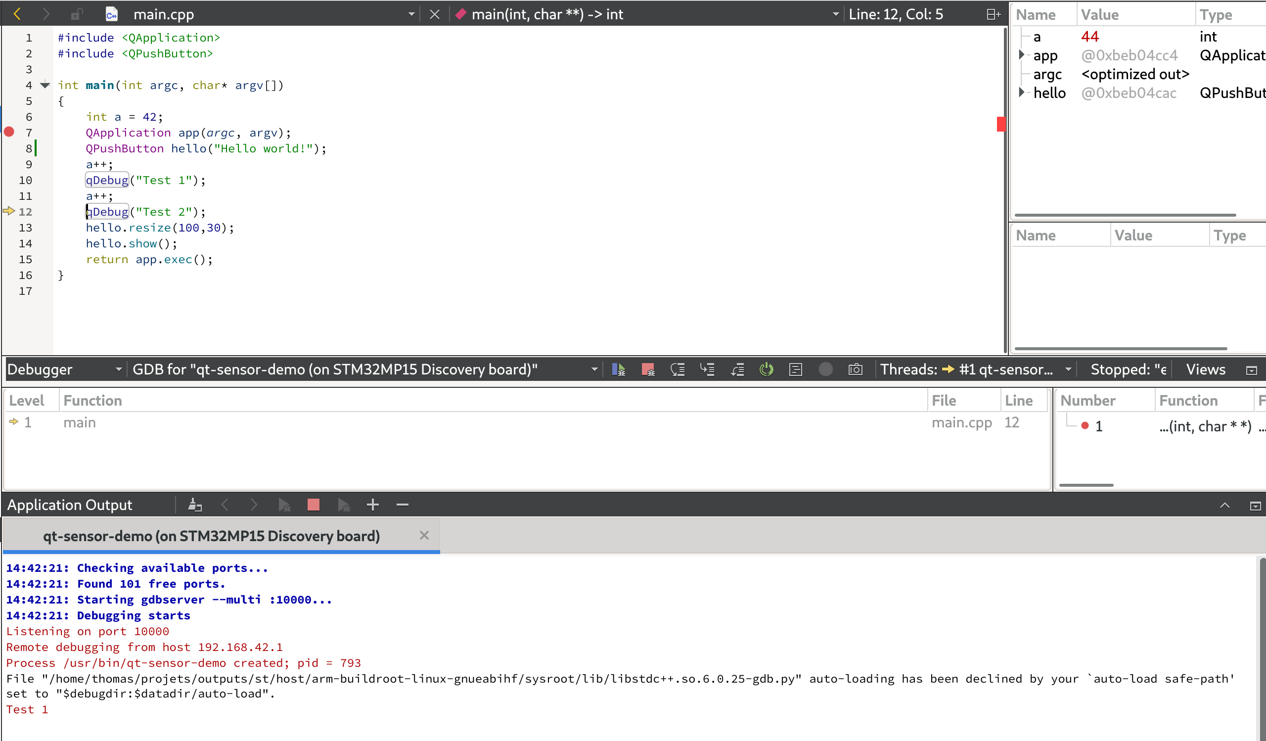
For this project, we wanted an I2C sensor that was at least capable of measuring the temperature, so we simply started by searching i2c temperature sensor on Amazon. After a bit of research, we found that the BME280 sensor from Bosch was available on several inexpensive break-out boards, and it already had a device driver in the upstream Linux kernel. When choosing hardware, it is always important to check whether it is already supported or not in the upstream Linux kernel. Having a driver already integrated in the upstream Linux kernel has a number of advantages:
The driver is readily available, you don’t have to integrate a vendor-provided driver, with all the possible integration issues
The driver has been reviewed by the Linux kernel maintainers, so you can be pretty confident of the code quality
The driver is using standard Linux interfaces, and not some vendor-specific one
The driver will be maintained in the long run by the kernel community, so you can continue to update your Linux kernel to benefit from security updates, bug fixes and new features
In addition, it also turns out that the BME280 sensor not only provides temperature sensing, but also pressure and humidity, which makes it even more interesting.
Among the numerous inexpensive BME280 break-out boards, we have chosen specifically this one, but plenty of others are available. The following details will work with any other BME280-based break-out board.
Connecting the I2C sensor
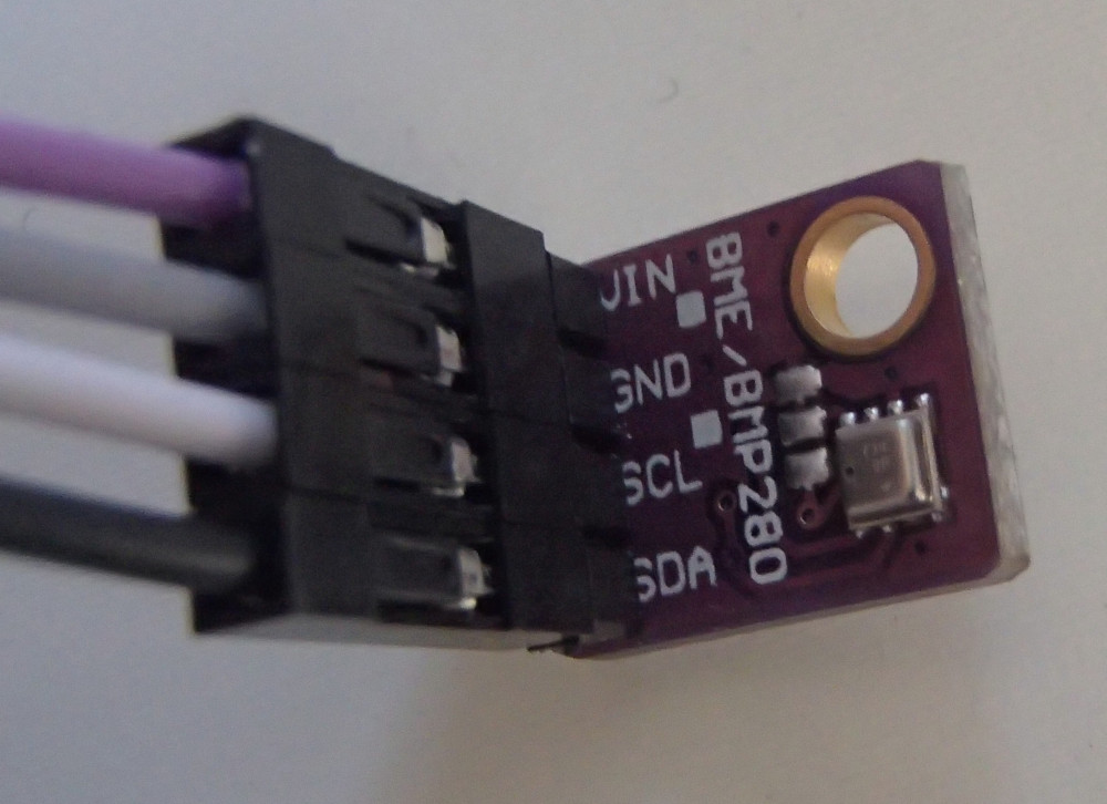
From a connectivity point of view, our I2C sensor is pretty simple: a VIN signal for power, a GND signal for ground, a SCL for the I2C clock and a SDA for the I2C data.
To understand how to connect this sensor to the Discovery board, we need to start with the board user manual.
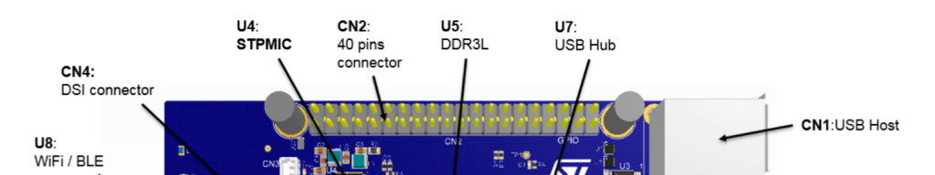
The Discovery board has two main expansion connectors: CN2 and the Arduino connectors.
Connector CN2
Connector CN2 is a 40-pin male header on the front side of the board:
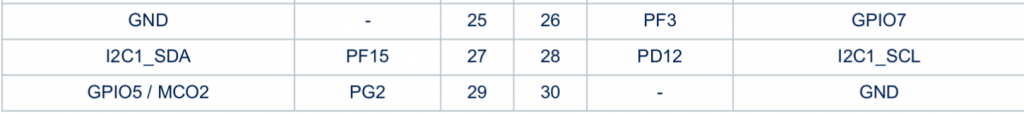
Section 7.17 of the board user manual documents the pin-out of this connector. There is one I2C bus available, through the I2C1_SDA (pin 27) and I2C1_SCL (pin 28) signals.
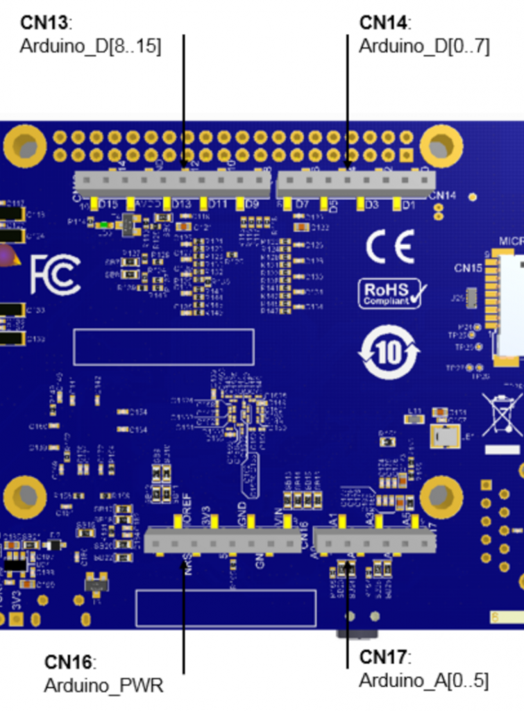
Arduino connectors
Connectors CN13, CN14, CN16, CN17 are female connectors on the back side of the board. They are compatible in pin-out and form-factor with the Arduino connector:
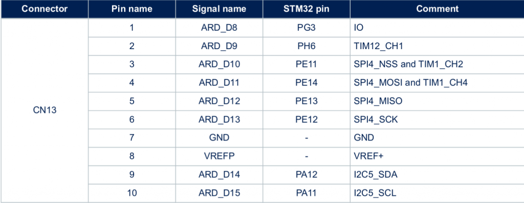
Section 7.16 of the board user manual documents the pin-out for these connectors. There is one I2C bus available as well in CN13, through the I2C5_SDA (pin 9) and I2C5_SCL (pin 10) signals.
Choosing the connector
According to the block diagram in Figure 3 of the board user manual, the I2C1 bus is already used to connect the touchscreen, the USB hub, the audio codec and the HDMI transceiver. However, I2C5 doesn’t seem to be used at all. In addition, with the screen mounted on the Discovery board, the CN2 connector is beneath the screen, which makes it a bit more difficult to use than the Arduino connectors on the back side.
We will therefore use the I2C5 bus, through the Arduino connector CN13. Pin 9 will be used to connect the data signal of our sensor, and pin 10 will be used to connect the clock signal of our sensor.
Finalizing the connectivity
We still have to find out how to connect the VIN and GND pins. According to the BME280 datasheet, VDDmain supply voltage range: 1.71V to 3.6V. The Arduino connector CN16 provides either 3.3V or 5V, so we’ll chose 3.3V (pin 4). And this connector also has multiple ground pins, among which we will chose pin 6.
Overall, this gives us the following connections:
Sensor signal
Arduino connector
Pin
VIN
CN16
pin 4
GND
CN16
pin 6
SDA
CN13
pin 9
SCL
CN13
pin 10
Here are a few pictures of the setup. First, on the sensor side, we have a purple wire for VIN, a grey wire for GND, a white wire for SCL and a black wire for SDA:
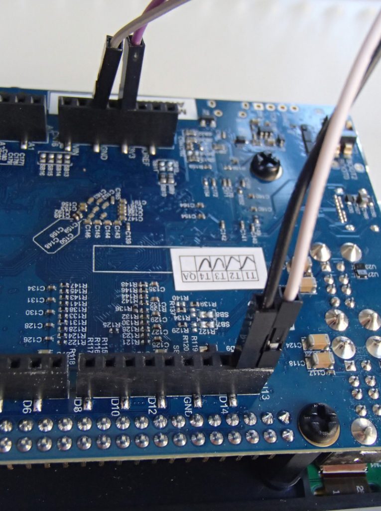
On the board side, we can see the purple wire (VIN) going to pin 4 of CN16, the grey wire (GND) going to pin 6 of CN16, the white wire (SCL) going to pin 10 of CN13 and the black wire (SDA) going to pin 9 of CN13.
With this we’re now all set in terms of hardware setup, let’s move on to enabling the I2C bus in Linux!
Enabling the I2C bus
An introduction to the Device Tree
In order to enable the I2C bus, we’ll need to modify the Device Tree, so we’ll first need to give a few details about what Device Tree is. If you read again our previous blog post in this series, we already mentioned the Device Tree. As part of the Buildroot build process, a file called stm32mp157c-dk2.dtb is produced, and this file is used at boot time by the Linux kernel: it is the Device Tree.
On most embedded architectures, devices are connected using buses that do not provide any dynamic enumeration capabilities. While buses like USB or PCI provide such capabilities, popular buses used on embedded architectures like memory-mapped buses, I2C, SPI and several others do not allow the operating system to ask the hardware: what peripherals are connected ? what are their characteristics ?. The operating system needs to know which devices are available and what their characteristics are. This is where the Device Tree comes into play: it is a data structure that describes in the form of a tree all the devices that we have in our hardware platform, so that the Linux kernel knows the topology of the hardware.
On ARM platforms, each particular board is described by its own Device Tree file. In our case, the STM32MP157 Discovery Kit 2 is described by the Device Tree file arch/arm/boot/dts/stm32mp157c-dk2.dts in the Linux kernel source code. This human-readable source file, with a .dts extension, is compiled during the Linux kernel build process into a machine-readable binary file, with a .dtb extension.
This stm32mp157c-dk2.dts describes the hardware of our Discovery Kit 2 platform. In fact, it only describes what is specific to the Discovery Kit 2: the display panel, the touchscreen, the WiFi and Bluetooth chip. Everything else is common with the Discovery Kit 1 platform, which is why the stm32mp157c-dk2.dts file includes the arm/boot/dts/stm32mp157a-dk1.dts file. Indeed, stm32mp157a-dk1.dts describes the hardware on the Discovery Kit 1, which is the same as the Discovery Kit 2, without the display, touchscreen and WiFi/Bluetooth chip.
In turn, the stm32mp157a-dk1.dts includes three other Device Tree files:
arm/boot/dts/stm32mp157c.dtsi, which describes all the devices inside the STM32MP157 system-on-chip. It will be used by all Device Tree files describing boards based on the STM32MP157 processor.
At this point, we won’t give much more generic details about the Device Tree, as it’s an entire topic on its own. For additional details, you could check the Device Tree for Dummies presentation from your author (slides, video) or the devicetree.org web site.
I2C controllers in the Device Tree
Zooming in to the topic of I2C, we can see that arm/boot/dts/stm32mp157c.dtsi describes 6 I2C controllers through six different nodes in the Device Tree:
i2c1: i2c@40012000
i2c2: i2c@40013000
i2c3: i2c@40014000
i2c4: i2c@5c002000
i2c5: i2c@40015000
i2c6: i2c@5c009000
This list of six I2C controllers nice matches the list of I2C controllers in the STM32MP157 datasheet, and their base address in the memory map, section 2.5.2:
In the file arm/boot/dts/stm32mp157a-dk1.dts, we can see that the I2C1 bus is enabled, and that a cs42l51 audio codec (I2C address 0x4a) and a sii9022 HDMI transceiver (I2C address 0x39) are connected to it:
to enable the bus. This piece of code adds the following Device Tree properties to the I2C5 Device Tree node:
status = "okay" which simply tells the Linux kernel: I really intend to use this device, so please enable whatever driver is needed to use this device
clock-frequency = <100000> tells Linux at which frequency we want to operate the I2C bus: in this case, 100 kHz
The pinctrl properties configure the pin muxing, so that the pins are configured in the I2C function when the system is running (the default state) and into a different state to preserve power when the system is in suspend to RAM (sleep state). Both i2c5_pins_a and i2c5_pins_sleep_a are already defined in arch/arm/boot/dts/stm32mp157-pinctrl.dtsi.
For now, this doesn’t describe any device on the bus, but should be sufficient to have the bus enabled in Linux. The question now is how to make this modification in our Device Tree in the proper way ?
Changing the Linux kernel source code
When Buildroot builds each package, it extracts its source code in output/build/<package>-<version>, so the source code of our Linux kernel has been extracted in output/build/linux-custom/. One could therefore be tempted to make his code changes directory in output/build/linux-custom/, but this has a number of major drawbacks:
output/build/linux-custom/ is not under version control: it is not part of a Linux kernel Git repository, so you can’t version control your changes, which is really not great
output/build/linux-custom/ is a temporary folder: if you do a make clean in Buildroot, this folder will be entirely removed, and re-created during the next Buildroot build
So, while doing a change directly in output/build/linux-custom/ is perfectly fine for quick/temporary changes, it’s not a good option to make changes that will be permanent.
To do this in a proper way, we will use a feature of Buildroot called pkg_OVERRIDE_SRCDIR, which is documented in section 8.12.6 Using Buildroot during development of the Buildroot manual. This feature allows to tell Buildroot: for a given package, please don’t download it from the usual location, but instead take the source code from a specific location on my system. This specific location will of course be under version control, and located outside of Buildroot, which allows to solve the two issues mentioned above.
So, let’s get set this up for the Linux kernel source code:
Start in the parent folder of Buildroot, so that the Linux kernel source code ends up being side-by-side with Buildroot
Clone the official upstream Linux kernel repository. Even though we could directly clone the STMicro Linux kernel repository, your author always finds it nicer to have the origin Git remote set up to the official upstream Git repository.
Fetch all the changes from the STMicro Linux kernel repository:
git fetch stmicro
Create a new branch, called bme280, based on the tag v4.19-stm32mp-r1.2. This tag is the one used by our Buildroot configuration as the version of the Linux kernel. The following command also moves to this new branch as the same time:
git checkout -b bme280 v4.19-stm32mp-r1.2
At this point, our linux/ folder contains the exact same source code as what Buildroot has retrieved. It is time to make our Device Tree change by editing arch/arm/boot/dts/stm32mp157c-dk2.dts and at the end of it, add:
Once done, we need to tell Buildroot to use our kernel source code, using the pkg_OVERRIDE_SRCDIR mechanism. To this, create a file called local.mk, in the top-level Buildroot source directory, which contains:
LINUX_OVERRIDE_SRCDIR = $(TOPDIR)/../linux
This tells Buildroot to pick the Linux kernel source from $(TOPDIR)/../linux. We’ll now ask Buildroot to wipe out its Linux kernel build, and do a build again:
$ make linux-dirclean
$ make
If you look closely at what Buildroot will do, it will do a rsync of the Linux kernel source code from your linux/ Git repository to output/build/linux-custom in Buildroot, and then do the build. You can check output/build/linux-custom/arch/arm/boot/dts/stm32mp157c-dk2.dts to make sure that your I2C5 change is there!
If that is the case, then reflash output/images/sdcard.img on your SD card, and run the new system on the board. It’s now time to test the I2C bus!
Testing the I2C bus
After booting the new system on your Discovery board and logging in as root, let’s have a look at all I2C related devices:
This folder is part of the sysfs filesystem, which is used by the Linux kernel to expose to user-space applications all sort of details about the hardware devices connected to the system. More specifically, in this folder, we have symbolic links for two types of devices:
The I2C busses: i2c-0, i2c-1, i2c-2 and i2c-3. It is worth mentioning that the bus numbers do not match the datasheet: they are simply numbered from 0 to N. However, the i2c-0 symbolic link shows it’s the I2C controller at base address 0x40012000, so it’s I2C1 in the datasheet, i2c-1 is at base address 0x40015000 so it’s I2C5 in the datasheet, and i2c-2 at base address 0x5c002000 is I2C4 in the datasheet. i2c-3 is special as it’s not an I2C bus provided by the SoC itself, but the I2C bus provided by the HDMI transmitter to talk with the remote HDMI device (since this is unrelated to our discussion, we won’t go into more details on this).
The I2C devices: 0-002a, 0-0038, 0-0039, 0-004a, 2-0028, 2-033. These entries have the form B-SSSS where B is the bus number and SSSS is the I2C address of the device. So you can see that for example 0-004a corresponds to the cs42l51 audio codec we mentioned earlier.
In our case, we are interested by I2C5, which is known by Linux as i2c-1. We will use the i2cdetect utility, provided by Busybox, to probe the different devices on this bus:
The device at 0x76 has disappeared, so it looks like our sensor is at I2C address 0x76. To confirm this, let’s have a look at what the BME280 datasheet says about the I2C address of the device, in section 6.2 I2C Interface:
So, the I2C address is indeed 0x76 when the SDO pin of the sensor is connected to GND, which is probably what our BME280 break-out board is doing. It matches the address we have detected with i2cdetect!
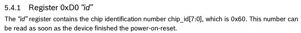
Now, let’s talk to our device. According to section 5.4 Register description of the datasheet, there is a Chip ID register, at offset 0xD0 that is supposed to contain 0x60:
We can read this register using the i2cget command:
# i2cget -y 1 0x76 0xd0
0x60
Good, this matches the expected value according to the BME280 datasheet, so it seems like communication with our I2C device is working, let’s move on to enabling the BME280 sensor driver.
Enabling the sensor driver
As discussed earlier, this BME280 sensor already has a driver in the upstream Linux kernel, in the IIO subsystem. IIO stands for Industrial Input/Output, and this subsystems contains a lot of drivers for various ADCs, sensors and other types of measurement/acquisition devices. In order to use this driver for our BME280 device, we will essentially have to do two things:
Enable the driver in our Linux kernel configuration, so that the driver code gets built as part of our kernel image
Describe the BME280 device in our Device Tree so that the Linux kernel knows we have one such device, and how it is connected to the system
Adjusting the kernel configuration
In the previous blog post, we explained that the Linux kernel configuration used to build the kernel for the STM32 Discovery board was located at board/stmicroelectronics/stm32mp157-dk/linux.config. Obviously, we are not going to edit this file manually: we need to run the standard Linux kernel configuration tools.
It turns out that Buildroot has convenient shortcuts to manipulate the Linux kernel configuration. We can run the Linux kernel menuconfig configuration tool by running:
$ make linux-menuconfig
At this point, it is really important to not be confused by the fact that both Buildroot and the Linux kernel use the same configuration utility, but each have its own configuration. The Buildroot configuration describes your overall system (target architecture, which software components you want, which type of filesystem you want, etc.) while the Linux kernel configuration describes the kernel configuration itself (which drivers you want, which kernel features you need, etc.). So make sure to not confuse the menuconfig of Buildroot with the menuconfig of the Linux kernel!
Once you have run make linux-menuconfig, the menuconfig of the Linux kernel will show up. You will then enable the following option:
Make sure to enable this option with a star <*> so that the driver is compiled inside the kernel image itself and not as a separate kernel module. You can then exit the menuconfig utility, and confirm that you want to save the configuration.
At this point, the Linux kernel configuration file in output/build/linux-custom/.config has been changed. You can confirm it by running:
However, as we explained earlier, the output/build/linux-custom/ folder is temporary: it would be removed when doing a Buildroot make clean. We would like to permanently keep our Linux kernel configuration. Once again, Buildroot provides a nice shortcut to do this:
$ make linux-update-defconfig
After running this command, the kernel configuration file board/stmicroelectronics/stm32mp157-dk/linux.config has been updated, and this file is not temporary, and is under version control. If you run git diff, you can see the change on this file:
We now need to tell the Linux kernel that we have a BME280 sensor and how it is connected to the system, which is done by adding more details into our Device Tree. We have already enabled the I2C5 bus, and we now need to describe one device connected to it: this gets done by creating a child node of the I2C controller node.
How do we know what to write in the Device Tree node describing the BME280 ? Using Device Tree bindings. Those bindings are specification documents that describe how a given device should be represented in the Device Tree: which properties are available, what are their possible values, etc. All Device Tree bindings supported by the Linux kernel are documented in Documentation/devicetree/bindings in the Linux kernel source code. For our BME280 device, the binding is at Documentation/devicetree/bindings/iio/pressure/bmp085.yaml.
This document tells us that we have one required property, the compatible property, with the range of possible values. Since we have a BME280 sensor, we’ll use bosch,bme280. The other properties are optional, so we’ll ignore them for now. This binding also documents a reg property, which is used to provide to the Linux kernel the I2C address of the device.
So, we’ll go back to our linux/ directory outside of Buildroot, where we cloned the Linux kernel repository, and we’ll adjust our Device Tree file arch/arm/boot/dts/stm32mp157c-dk2.dts so that it contains:
Let’s now ask Buildroot to rebuild the Linux kernel, with our Device Tree change and kernel configuration change. Instead of rebuilding from scratch, we’ll just ask Buildroot to restart the build of the Linux kernel, which will be much faster:
$ make linux-rebuild
As part of this, Buildroot will re-run rsync from our linux/ kernel Git repository to output/build/linux-custom/, so that we really build the latest version of our code, which includes our Device Tree change.
However, this just rebuilds the Linux kernel, and not the complete SD card image, so also run:
$ make
To regenerate the SD card image, write it on your SD card, and boot your system.
Testing the sensor
After booting the system, if we check /sys/bus/i2c/devices, a new entry has appeared:
If we following this symbolic link, we can see a number of interesting information:
# ls -l /sys/bus/i2c/devices/1-0076/
total 0
lrwxrwxrwx    driver -> ../../../../../../bus/i2c/drivers/bmp280
drwxr-xr-x    iio:device2
-r--r--r--    modalias
-r--r--r--    name
lrwxrwxrwx    of_node -> ../../../../../../firmware/devicetree/base/soc/i2c@40015000/pressure@76
drwxr-xr-x    power
lrwxrwxrwx    subsystem -> ../../../../../../bus/i2c
-rw-r--r--    uevent
Here we can see that this device is bound with the device driver named bmp280, and that its Device Tree node is base/soc/i2c@40015000/pressure@76.
Now, to actually use the sensor, we need to understand what is the user-space interface provided by IIO devices. The kernel documentation gives some hints:
There are two ways for a user space application to interact with an IIO driver.
/sys/bus/iio/iio:deviceX/, this represents a hardware sensor and groups together the data channels of the same chip.
/dev/iio:deviceX, character device node interface used for buffered data transfer and for events information retrieval.
So, we’ll try to explore the /sys/bus/iio/ option:
Here we can see a number of IIO devices: our IIO device is iio:device2, as can be seen by looking at the target of the symbolic links. The other ones are IIO devices related to the ADC on the STM32 processor. Let’s check what we have inside /sys/bus/iio/devices/iio:device2/:
# ls -l /sys/bus/iio/devices/iio\:device2/
total 0
-r--r--r--    dev
-rw-r--r--    in_humidityrelative_input
-rw-r--r--    in_humidityrelative_oversampling_ratio
-rw-r--r--    in_pressure_input
-rw-r--r--    in_pressure_oversampling_ratio
-r--r--r--    in_pressure_oversampling_ratio_available
-rw-r--r--    in_temp_input
-rw-r--r--    in_temp_oversampling_ratio
-r--r--r--    in_temp_oversampling_ratio_available
-r--r--r--    name
lrwxrwxrwx    of_node -> ../../../../../../../firmware/devicetree/base/soc/i2c@40015000/pressure@76
drwxr-xr-x    power
lrwxrwxrwx    subsystem -> ../../../../../../../bus/iio
-rw-r--r--    uevent
This is becoming interesting! We have a number of files that we can read to get the humidity, pressure, and temperature:
What:		/sys/bus/iio/devices/iio:deviceX/in_tempX_input
Description:
		Scaled temperature measurement in milli degrees Celsius.

What:		/sys/bus/iio/devices/iio:deviceX/in_pressure_input
Description:
		Scaled pressure measurement from channel Y, in kilopascal.

What:		/sys/bus/iio/devices/iio:deviceX/in_humidityrelative_input
Description:
		Scaled humidity measurement in milli percent.
So here we are: we are able to read the data from our sensor, and the Linux kernel driver does all the conversion work to convert the raw values from the sensors into usable values in meaningful units.
Turning our kernel change into a patch
Our Device Tree change is for now only located in our local Linux kernel Git repository: if another person builds our Buildroot configuration, he won’t have access to this Linux kernel Git repository, which Buildroot knows about thanks to the LINUX_OVERRIDE_SRCDIR variable. So what we’ll do now is to generate a Linux kernel patch that contains our Device Tree change, add it to Buildroot, and ask Buildroot to apply it when building the Linux kernel. Let’s get started.
First, go in your Linux kernel Git repository in linux/, review your Device Tree change with git diff, and if everything is alright, make a commit out of it:
$ git commit -as -m "ARM: dts: add support for BME280 sensor on STM32MP157 DK2"
Then, generate a patch out of this commit:
$ git format-patch HEAD^
This will create a file called 0001-ARM-dts-add-support-for-BME280-sensor-on-STM32MP157-.patch that contains our Device Tree change.
Now, back in Buildroot in the buildroot/ folder, create the board/stmicroelectronics/stm32mp157-dk/patches/ folder and a sub-directory board/stmicroelectronics/stm32mp157-dk/patches/linux. Copy the patch into this folder, so that the file hierarchy looks like this:
And in Build options, set global patch directories to the value board/stmicroelectronics/stm32mp157-dk/patches/. This tells Buildroot to apply patches located in this folder whenever building packages. This way, when the linux package will be built, our patch in board/stmicroelectronics/stm32mp157-dk/patches/linux/ will be applied.
We can now remove the local.mk file to disable the pkg_OVERRIDE_SRCDIR mechanism, and ask Buildroot to rebuild the Linux kernel:
$ rm local.mk
$ make linux-dirclean
$ make
If you pay attention to the Linux kernel build process, you will see that during the Patching step, our Device Tree patch gets applied:
>>> linux custom Patching

Applying 0001-ARM-dts-add-support-for-BME280-sensor-on-STM32MP157-.patch using patch:
patching file arch/arm/boot/dts/stm32mp157c-dk2.dts
You can of course reflash the SD card at the end of the build, and verify that everything still works as expected.
We can now share our Buildroot change with others: they can build our improved system which has support for the BME280 sensor.
Conclusion
You can find the exact Buildroot source code used to reproduce the system used in this article in the branch at 2019.02/stm32mp157-dk-blog-2.
In this article, we have learned a lot of things:
How to connect an I2C sensor to the Discovery board
What is the Device Tree, and how it is used to describe devices
How to use Buildroot’s pkg_OVERRIDE_SRCDIR mechanism
How to enable the I2C bus in the Device Tree and test its operation using i2cdetect and i2cget
How to change the Linux kernel configuration to enable a new driver
How to interact using sysfs with a sensor supported by the IIO subsystem
How to generate a Linux kernel patch, and add it into Buildroot
In our next article, we’ll look at adding support for the Qt5 graphical library into our system, as a preparation to developing a Qt5 application that will display our sensor measurements on the Discovery board screen.