Bootlin is really happy to welcome another engineer in its team: Jérémie Dautheribes, who joined us on November 2, 2022.
Jérémie Dautheribes graduated in 2020 with a master degree in Ambiant, Mobile and Embedded Systems from the Toulouse University. After graduating, he worked at the french research institute INRIA on cache optimization for FreeRTOS multicore programs, and then in a company called EPSI where he was in charge of developing and maintaining Linux-based BSPs for i.MX6 and Tegra platforms, based on Yocto.
In addition, Jérémie has some experience in using the Rust programming language for low-level development, a skill that might prove to be useful for doing Linux kernel development in the future!
Linux 6.0 has been released two weeks ago, and Linux 6.1-rc1 is already out of the door, but we didn’t get the chance to look at the contributions made by Bootlin to the Linux 6.0 release. Before we do that, let’s provide our usual must-read articles on Linux 6.0: the Linux 6.0 merge window part 1 and Linux 6.0 merge window part 2 LWN.net articles and the KernelNewbies.org article.
On Bootlin side, our significant contributions to this release have been:
Clément Léger contributed a new driver for the Ethernet switch found in the Renesas RZ/N1 processor, as well as a PCS driver for the MII converter of the same processor. Obviously, this came with the related Device Tree bindings and Device Tree changes, but also with a few small changes in the DSA subsystem.
Hervé Codina enabled support for the PCIe controller found in the same Renesas RZ/N1 processor, which in fact does not allow to use PCIe devices, but USB devices: this PCIe controller is only used to connect to an internal USB controller in the chip, which therefore allows to use USB devices.
Köry Maincent extended the existing mpc4922 DAC IIO driver to also support the mpc4921 variant, which has only one output channel instead of two.
Luca Ceresoli contributed several improvements to the I2C subsystem documentation.
Paul Kocialkowski contributed two new V4L drivers for the MIPI CSI-2 camera interfaces available in the Allwinner A31 family of processors (sun6i) and the Allwinner A83T family of processors (sun8i).
Here is the full details of our contributions, commit by commit:
Here are the quickest instructions (I hope) for having the Yocto Project build an embedded Linux image for BeagleBone boards based on the TI AM335x CPU:
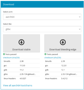
The toolchains.bootlin.com service provides freely available pre-compiled cross-compilation toolchains for a wide range of CPU architectures and configurations.
We have just published version 2022.08 of these toolchains, which are now built using Buildroot 2022.08. Thanks to this the toolchains now use the following components:
The bleeding-edge toolchains are based on gcc 12, binutils 2.39, gdb 12, kernel headers 5.4, glibc 2.35 or musl 1.2.3 or uclibc-ng 1.0.42.
The stable toolchains are based on gcc 11, binutils 2.38, gdb 11, kernel headers 4.9, glibc 2.35 or musl 1.2.3 or uclibc-ng 1.0.42.
Even though glibc 2.36 has been recently released, it still caused too many issues to be integrated in this toolchain release. glibc 2.36 will be part of a future update of these toolchains.
We also have a few new toolchains that appeared:
Toolchains for the OpenRISC CPU architecture, based on the glibc C library. We already had toolchains for OpenRISC, but not using glibc.
We now have both stable and bleeding-edge toolchains for the x86-64-v2, x86-64-v3 and x86-64-v4 architecture variants. We used to have only bleeding-edge toolchains for these variants as only the latest gcc had support for them.
The only toolchain that was not updated as part of this release is the m68k Coldfire toolchain, as we currently have a regression on elf2flt. This will hopefully be adressed in the future.
If you have feedback or encounter any issue in using these toolchains, the project issue tracker is where you should go.
As part of a team effort to improve the upstream Linux kernel support for the Renesas RZ/N1 ARM processor, we had to write from scratch a new RTC driver for this SoC. The RTC subsystem API is rather straightforward but, as most kernel subsystems, the documentation about it is rather sparse. So what are the steps to write a basic RTC driver? Here are some pointers.
The registration
The core expects drivers to allocate, initialize and then register a struct rtc_device with the device managed helpers: devm_rtc_allocate_device() and devm_rtc_register_device(). Between these two function calls, one will be required to provide at least a set of struct rtc_class_ops which contains the various callbacks used to access the device from the core, as well as setting a few information about the device.
The kind of information expected is the support for various features (rtcdev->features bitmap) as well as the maximum continuous time range supported by your RTC. If you do not know the actual date after which your device stops being reliable, you can use the rtc-range test tool from rtc-tools, available at https://git.kernel.org/pub/scm/linux/kernel/git/abelloni/rtc-tools.git (also available as a Buildroot package). It will check the consistency of your driver against a number of common known-to-be-failing situations.
Time handling
The most basic operations to provide are ->read_time() and ->set_time(). Both functions should play with a struct rtc_time which describes time and date with members for the year, month, day of the month, hours (in 24-hour mode), minutes and seconds. The week day member is ignored by userspace and is not expected to be set properly, unless it is actively used by the RTC, for example to set alarms. There are then three popular ways of storing time in the RTC world:
either using the binary values of each of these fields
or using a Binary Coded Decimal (BCD) version of these fields
or, finally, by storing a timestamp in seconds since the epoch
In BCD, each decimal digit is encoded using four bits, eg. the number 12 could either be coded by 0x0C in hexadecimal, or 0x12 in BCD, which is easier to read with a human eye.
The three representations are absolutely equivalent and you are free to convert the time from one system to another when needed:
#1 <-> #2 conversions are done with bcd2bin() and bin2bcd() (from linux/bcd.h)
#1 <-> #3 conversions are done with rtc_time64_to_tm() and rtc_tm_to_time64() (from linux/rtc.h)
While debugging, it is likely that you will end up dumping these time structures. Note that struct rtc_time is aligned on struct tm, this means that the year field is the number of years since 1900 and the month field is the number of months since January, in the range 0 to 11. Anyway, dumping these fields manually is a loss of time, it is advised instead to use the dedicated RTC printk specifiers which will handle the conversion for you: %ptR for a struct rtc_time, %ptT for a time64_t.
Of course, when reading the actual time from multiple registers on the device and filling those fields, be aware that you should handle possible wrapping situations. Either the device has an internal latching mechanism for that (eg. the front-end of the registers that you must read are all frozen upon a specific action) or you need to verify this manually by, for instance, monitoring the seconds register and try another read if it changed between the beginning and the end of the retrieval.
If your device continuous time range ended before 2000 you may want to shift the default hardware range further by providing the start-year device tree property. The core will then shift the Epoch further for you.
Finally, once done, you can verify your implementation by playing with the rtc test tool (also from rtc-tools).
Supporting alarms
One common RTC feature is the ability to trigger alarms at specific times. Of course it’s even better if your RTC can wake-up the system.
If the device or the way it is integrated doesn’t support alarms, this should be advertised at registration time by clearing the relevant bit (RTC_FEATURE_ALARM, RTC_FEATURE_UPDATE_INTERRUPT). In the other situations, it is relevant to indicate whether the RTC has a second, 2-seconds or minute resolution by setting the appropriate flag (RTC_FEATURE_ALARM_RES_2S, RTC_FEATURE_ALARM_RES_MINUTE). Mind when testing that querying an alarm time below this resolution will return a -ETIME error.
When implementing the ->read_alarm(), ->set_alarm() and ->alarm_irq_enable() hooks, be aware that the update and periodic alarms are now implemented in the core, using HR timers rather than with the RTC so you should focus on the regular alarm. The read/set hooks naturally allow to read and change the alarm settings. A struct rtc_wkalrm *alrm is passed as parameter, alrm->time is the struct rtc_time and alrm->enabled the state of the alarm (which must be set in ->set_alarm()). The third hook is an asynchronous way to enable/disable the alarm IRQ.
The interrupt handler for the alarm is required to call rtc_update_irq() to signal the core that an alarm happened, providing the RTC device, the number of alarms reported (usually one), and the RTC_IRQF flag OR’ed with the relevant alarm flag (likely, RTC_AF for the main alarm).
Oscillator offset compensation
RTC counters rely on very precise clock sources to deliver accurate times. To handle the situation where the source is not matching the expected precision, which is the case with most cheap oscillators on the market, some RTCs have a mechanism allowing to compensate for the frequency variation by incrementing or skipping the RTC counters at a regular interval in order to get closer to the reality.
The RTC subsystem offers a set of callbacks, ->read_offset() and a ->set_offset(), where a signed offset is passed in ppb (parts per billion).
As an example, if an oscillator is below its targeted frequency of 32768 Hz and is measured to run at 32767.7 Hz, we need to offset the counter by 1 - (32767.7/32768) = 9155 ppb. If the RTC is capable of offsetting the main counter once every 20s it means that every 20s, this counter (which gets decremented at the frequency of the oscillator to produce the “seconds”) will start at a different value than 32768. Adding 1 to this counter every 20s would basically mean earning 1 / (32768 * 20) = 1526 ppb. Our target being 9155 ppb, we must offset the counter by 9155 / 1526 = 6 every 20s to get a compensated rate of 32767.7 + (6 / 20) = 32768 Hz.
Upstreaming status of the RZ/N1 RTC driver
The RZ/N1 RTC driver has all the features listed above and made its way into the v5.18 Linux kernel release. Hopefully this little reference sheet will encourage others to finalize and send new RTC drivers upstream!
Buildroot is an easy-to-use and popular embedded Linux build system, used by many as an alternative to Yocto/OpenEmbedded. Bootlin has expertise in both build systems, and has in particular been a long time contributor to the Buildroot project. Bootlin CEO’s Thomas Petazzoni is one of the co-maintainers of the project, to which he has contributed over 5000 patches.
The main goal of this hackathon was to reduce the backlog of patches accumulated in the project’s patchwork, the tool used in the Buildroot community to record all contributed patches and make sure all of them are handled: reviewed, accepted, or potentially rejected.
When we started the hackathon, the backlog of patches cumulated to over 410 patches, and the hackathon allowed to reduce the backlog to 150-160 patches, especially taking care of all patches contributed before the beginning of 2022. In total, over 400 patches were merged during the hackathon in the Buildroot Git repository, which obviously is more than the reduction of the backlog of patches. This is mainly due to additional patches contributed during the hackathon itself (the community has been very active at submitting new patches!) and due to the review process triggering additional ideas or rework that required more patches.
Here is a summary of the main highlights that were merged during this hackathon:
New package for ntpsec, a “a secure, hardened, and improved implementation of Network Time Protocol”
Some cleanup of the genimage configuration files to use shortcuts for common GPT partition GUIDs
Test cases added for the get-developers script
Addition of several new defconfigs for multiple RISC-V 64-bit noMMU platforms: Sipeed MAIX-Bit, Sipeed MAIXDUINO, Sipeed MAIX-Dock, Sipeed MAIX-Go and Canaan KD233, based on Canaan K210 SoC.
Migration of the .py to .pyc byte-compilation to use the built-in Python infrastructure instead of a custom script.
Addition of support for version 12 of the GCC compiler. This means that GCC 11 is now the default in Buildroot, and support for GCC 9 has been removed.
Many new Python packages added: python-lark, python-typeguard, python-mypy-extensions, python-typing-inspect, python-rfc3987, python-ruamel-yaml, python-pyrsistent, python-pylibfdt, python-maturin
Rust has been bumped to 1.62.0
New package for mender-connect, a daemon responsible for handling bidirectional (websocket) communication with the Mender server
New package for OpenSC, a set of libraries and utilities to work with smart cards.
New package for hyperfine, a benchmark tool written in Rust. It evaluates execution time of a command passed in arguments and make a relative comparison if multiple arguments are used at the same time.
New package for hawktracer, a highly portable, low-overhead, configurable profiling tool built in Amazon Video for getting performance metrics from low-end devices.
New package for vis-network, a JS library to display dynamic, automatically organised, customizable network views
New package for Avocado, an automated testing suite containing tests for various subsystems.
New package for freeradius-server, an open source server which implements a protocol for remote user Authorization, Authentication and Accounting.
New package for volk, a Vector-Optimized Library of Kernels. It is a library that contains kernels of hand-written SIMD code for different mathematical operations.
A rework of the LTO handling: LTO support is now always enabled in GCC, and the new option BR2_ENABLE_LTO allows to request LTO to be used by packages that support it.
New package for the Qt 6 library, separate from the current Qt 5 package. For now, the Qt 6 package is very minimal: it only packages qt6base, and only the core of Qt, not even the GUI support is enabled. As part of this, the double-conversion and libb2 packages were added.
Support for configurable page size for ARM64 was added. In addition to the default 4 KB, 64 KB pages are supported. This includes some test cases that allow to validate the 64 KB ARM64 page size support in Qemu.
New package for clpeak, a tool that profiles OpenCL devices to find their peak capacities, together with its dependency OpenCL-CLHPP, the C++ bindings for OpenCL
A rework of several top-level menuconfig options: the “enable MMU” option is now part of the Target architecture menu, the Toolchain menu is now before the Build options menu, which allows the choice of the C library to be done before the choice of static vs. shared libraries. This allows the choice of static library to be made unavailable when glibc is selected, fixing a number of invalid configurations.
New package for GDAL, a translator library for raster and vector geospatial data formats.
New package for libutp, a uTorrent Transport Protocol library
New package for dust, an alternative written in Rust of the command “du”.
The C-SKY CPU architecture support was removed, as it was no longer maintained, and barely used.
New package for gitlab-runner, the open source project that is used to run your jobs and send the results back to GitLab
New package for dbus-broker, which is an alternative implementation of the D-Bus daemon, by the systemd community. It is integrated in Buildroot so that either classic D-Bus or dbus-broker can be used as the D-Bus daemon implementation.
New package for nerdctl, a Docker-compatible CLI for containerd, controlling runc.
A rework of how the udev hwdb is handled, to be consistent between systemd and eudev, and to remove useless hwdb source files from the target, as the hwdb is compiled at build time.
And at least 137 packages have seen their version bumped
Several other topics were looked at and discussed, but did not necessarily lead to patches already integrated. One such topic is the investigation of several issues with elf2flt, the tool used on noMMU architectures to produce binaries in the FLAT format, from an ELF binary. Another topic is the merge of the SciPy package, for which the review and testing is well advanced.
Overall, it was a very productive hackathon, and besides the massive work done on Buildroot from 9 AM to (at least) midnight each day, the participants also enjoyed lots of side discussions, embedded Linux related or not. We look forward to the next in-person gathering of the Buildroot community, on September 17/18 in Dublin, right after the Embedded Linux Conference Europe.
Linux 5.19 has been released yesterday. We recommend the usual resources of LWN (part 1 and part 2) as well as KernelNewbies to get some high-level overview of the major additions. CNX-Software also has an article focused on the ARM/RISC-V/MIPS improvements.
At Bootlin, we contributed 68 patches to this release, the main highlights being:
Clément Léger contributed patches for the Microchip SAMA5 platform to support suspend operation while running in non-secure mode, with OP-TEE handling the necessary PCSI calls. This is related to our work to port OP-TEE on Microchip SAMA5D2, which we have covered in severalblogposts before.
Hervé Codina contributed device Tree updates to enable the PCI controller of the Renesas RZ/N1 platform, which allows to access the USB host controller that sits on an internal PCI bus. Some driver updates for the PCI driver are needed, and they will land in 5.206.0 kernel.
Miquèl Raynal contributed several improvements to the IIO subsystem, following his work on several IIO drivers and his related blog post. These improvements either touch the core IIO, or fix some incorrect API use in IIO drivers.
Miquèl Raynal contributed a new driver for the Renesas RZ/N1 DMA router (in drivers/dmaengine) as well as a new driver for the Renesas RZ/N1 Real Time Clock (in drivers/rtc). In addition, Miquèl modified the 8250 UART controller driver to be able to use the DMA capabilities available on the RZ/N1 processor.
Miquèl Raynal also contributed a number of improvements to the IEEE 802.15.4 stack in the Linux kernel.
Paul Kocialkowski contributed support for MIPI CSI-2 in the Allwinner phy-sun6i-mipi-dphy driver.
Paul Kocialkowski and Luca Ceresoli contributed a few misc fixes, touching the SPI core and SPI Rockchip driver and the dmaengine documentation.
Let’s jump right in! In the previous article, we went through a theoretical overview of PipeWire. Our goal will now be to install and configure a minimal Linux-based system that runs PipeWire in order to output audio to an ALSA sink. The hardware for this demo will be a SAMA5D3 Xplained board and a generic USB sound card (a Logitech USB Headset H340 in our case, as reported by /sys/bus/usb/devices/MAJOR-MINOR/product).
We will rely on Buildroot for the root filesystem, and compile our Linux kernel outside Buildroot for ease of development. In the chronological order, here are the steps we’ll follow:
Download Buildroot and configure it. This step will provide us with two things: a cross-compiling toolchain and a root filesystem. We will use a pre-compiled toolchain as compiling a GCC toolchain is a slow process.
Download, configure and build the kernel. This will require small tweaks to ensure the right drivers are compiled-in. We will rely upon the Buildroot-provided toolchain, which will make allow our project to be self-contained and reduce the number of dependencies installed system-wide. This also leads to a more reproducible routine.
Boot our board; this requires a kernel image and a root filesystem. We’ll rely upon U-Boot’s TFTP support to retrieve the kernel image and Linux’s NFS support for root filesystems to allow for quick changes.
Iterate on 1, 2 and 3 as needed! We might want to change kernel options or add packages to our root filesystem.
Feel free to skip the steps that are not required for you if you plan to follow along, this probably assumes some small configuration changes here and there on your side.
Buildroot: toolchain & root filesystem
Let’s start with Buildroot:
$ export WORK_DIR=PATH/TO/WORKING/DIRECTORY/
$ cd $WORK_DIR

# Download and extract Buildroot
$ export BR2_VERSION=2022.02
$ wget "https://buildroot.org/downloads/buildroot-$BR2_VERSION.tar.gz"
$ tar xf buildroot-$BR2_VERSION.tar.gz
$ mv buildroot-$BR2_VERSION buildroot

# Hop into the config menu
$ cd buildroot
$ make menuconfig
# nconfig, xconfig and gconfig are also available options
It’s config time! We’ll use a pre-compiled glibc-based toolchain.
In “Target options”:
“Target architecture” should be “ARM (little endian)” (BR2_arm symbol);
“Target architecture variant” should be “cortex-A5” (BR2_cortex_a5);
“Enable VFP extension support” should be true (BR2_ARM_ENABLE_VFP);
In “Toolchain”:
“Toolchain type” should be “External toolchain” (BR2_TOOLCHAIN_EXTERNAL);
“Toolchain” should be “Bootlin toolchains” (BR2_TOOLCHAIN_EXTERNAL_BOOTLIN);
“Bootlin toolchain variant” should be “armv7-eabihf glibc stable 2021.11-1” (BR2_TOOLCHAIN_EXTERNAL_BOOTLIN_ARMV7_EABIHF_GLIBC_STABLE);
“Copy gdb server to the target” can be set to true, this might come in useful in such experiments (BR2_TOOLCHAIN_EXTERNAL_GDB_SERVER_COPY).
In “Build options”, various options could be modified based on preferences: “build packages with debugging symbols”, “build packages with runtime debugging info”, “strip target binaries” and “gcc optimization level”.
In “System configuration”, the root password can be defined (BR2_TARGET_GENERIC_ROOT_PASSWD symbol). Changing this from the default empty password will allow us to login using SSH.
In “Target packages”, we’ll list them using symbol names as that is easier to search:
BR2_PACKAGE_ALSA_UTILS with its APLAY option, to enable testing devices directly using ALSA;
From this article’s introduction, we know that we still need a session manager to go along with PipeWire. Both pipewire-media-session and WirePlumber are packaged by Buildroot but we’ll stick with WirePlumber as its the recommended option. At the place it should appear in the menuconfig is a message that tells us that we are missing dependencies:
*** wireplumber needs a toolchain w/ wchar, threads and Lua >= 5.3 ***
If in doubt of what causes this message to appear as it lists multiple dependencies, we can find the exact culprit by searching for the BR2_PACKAGE_WIREPLUMBER symbol in menuconfig, which tells us on which symbols WirePlumber depends on:
The depends on entry tells us the boolean expression that needs to be fullfilled for BR2_PACKAGE_WIREPLUMBER to be available. Next to each symbol name is its current value in square brackets.
Note: this process could have been done manually, by looking for the WirePlumber symbol definition in buildroot/package/wireplumber/Config.in and grepping our current .config, seeing what was missing.
The conclusion is that we are missing Lua, which is the scripting used throughout WirePlumber. Enabling BR2_PACKAGE_LUA makes the BR2_PACKAGE_WIREPLUMBER option available, which we enable.
In the Buildroot version we selected, the WirePlumber package lists PACKAGE_DBUS as an unconditional dependency in the WIREPLUMBER_DEPENDENCIES variable, in package/wireplumber/wireplumber.mk. However, WirePlumber can be built fine without it and we therefore need to remove it manually to build successfully our image. This has been fixed for upcoming Buildroot versions.
As often in Buildroot, packages have optional features that get enabled if dependencies are detected. make menuconfig won’t tell us about those, the best way is to browse the package/$PKG/$PKG.mk files for $PKG that interests us and see what gets conditionnally enabled. By visiting PipeWire’s and WirePlumber’s makefiles, we can see that we might want to enable:
BR2_PACKAGE_DBUS for various D-Bus-related features which we have explored in the first article; this allows building the SPA D-Bus support plugin relied upon by both PipeWire and WirePlumber, which explains why WirePlumber doesn’t directly depend upon D-Bus;
BR2_PACKAGE_HAS_UDEV to support detection of events on ALSA, V4L2 and libcamera devices;
BR2_PACKAGE_SYSTEMD for systemd unit files to get generated and systemd-journald support (logging purposes);
BR2_PACKAGE_ALSA_LIB for ALSA devices support (which also requires BR2_PACKAGE_ALSA_LIB_{SEQ,UCM} and BR2_PACKAGE_HAS_UDEV);
BR2_PACKAGE_AVAHI_LIBAVAHI_CLIENT for network discovery in various PipeWire modules: search for the avahi_dep symbol in PipeWire’s meson.build files for the list;
BR2_PACKAGE_NCURSES_WCHAR to build the pw-top monitoring tool;
BR2_PACKAGE_LIBSNDFILE to build the pw-cat tool (equivalent of alsa-tools’ aplay);
and a few others.
One option that needs discussion is the BR2_PACKAGE_HAS_UDEV. It is required to have the -Dalsa=enabled option at PipeWire’s configure step. As can be seen in PipeWire’s spa/meson.build, this option enforces that ALSA support gets built:
This line seems to indicate that to have ALSA support, we could simply add ALSA as a dependency and rely on the fact that the build system will find it. However, later on in the same Meson build file, we notice:
libudev_dep = dependency(
    'libudev',
    required: alsa_dep.found() or
        get_option('udev').enabled() or
        get_option('v4l2').enabled())
This line means that if the ALSA dependency is found, the libudev dependency is required which would lead to a failing build if we don’t have udev support.
As we expect ALSA support, we’ll make sure BR2_PACKAGE_HAS_UDEV is enabled. To find out what provides this config entry, the easiest way is a search through Buildroot for the select BR2_PACKAGE_HAS_UDEV string, which returns two results:
We’ll stick with eudev and avoid importing the whole of systemd in our root filesystem. To do so, we tell Buildroot to use eudev for /dev management in the “System configuration” submenu (the BR2_ROOTFS_DEVICE_CREATION_DYNAMIC_EUDEV symbol, which automatically selects BR2_PACKAGE_EUDEV).
In turn, PipeWire’s build configuration automatically enables some options if specific dependencies are found. That is why the package/pipewire/pipewire.mk file has sections such as:
That means pw-top will get built if ncursesw is found; for ncurses the trailing w means wide.
In our specific case, two tools that get conditionally built interest us: pw-top and pw-cat (and its aliases pw-play, pw-record, etc.). The first one will help us monitor the state of active nodes (their busy time, time quantum, etc.) and the second one is capable of playing an audio file by creating a PipeWire source node; it’s the equivalent of aplay, arecord, aplaymidi and arecordmidi. We therefore enable BR2_PACKAGE_NCURSES, BR2_PACKAGE_NCURSES_WCHAR and BR2_PACKAGE_LIBSNDFILE.
One last thing: let’s include an audio test file in our root filesystem image, for easy testing later on. We’ll create a root filesystem overlay directory for this:
$ cd $WORK_DIR
# Create an overlay directory with a .WAV example file
$ mkdir -p overlay/root
# This file is available under a CC BY 3.0 license, see:
# https://en.wikipedia.org/wiki/File:Crescendo_example.ogg
$ wget -O example.ogg \
    "https://upload.wikimedia.org/wikipedia/en/6/68/Crescendo_example.ogg"
# aplay only supports the .voc, .wav, .raw or .au formats
$ ffmpeg -i example.ogg overlay/root/example.wav
$ rm example.ogg

# Set BR2_ROOTFS_OVERLAY to "../overlay"
# This can be done through menuconfig as well
$ sed -i 's/BR2_ROOTFS_OVERLAY=""/BR2_ROOTFS_OVERLAY="..\\/overlay"/' \
    buildroot/.config
We now have a Buildroot configuration that includes BusyBox for primitive needs, Dropbear as an SSH server, PipeWire and its associated session manager WirePlumber, with automatic /dev management and tools that will help us in our tests (aplay and pw-play for outputting audio and pw-top to get an overview on PipeWire’s state). WirePlumber comes with a tool called wpctl that gets unconditionally built. make can be run in Buildroot’s folder so that both the cross-compiling toolchain and the root filesystem get generated and put into Buildroot’s output folder; see the manual for more information about Buildroot’s output/ directory. The toolchain’s GCC and binutils programs in particular can be accessed in output/host/bin/, all prefixed with arm-linux-.
Linux kernel
As we now have an available toolchain, we can go ahead by fetching, configuring and compiling the kernel:
# Download and extract the Linux kernel
$ export LINUX_VERSION=5.17.1
$ wget "https://cdn.kernel.org/pub/linux/kernel/v5.x/linux-$LINUX_VERSION.tar.xz"
$ tar xf linux-$LINUX_VERSION.tar.xz
$ mv linux-$LINUX_VERSION linux
If we compile the kernel as such, it wouldn’t know what our target architecture is and what toolchain to use (it would use what can be found in our $PATH environment variable, which is most probably not right). We therefore need to inform it using three environment variables:
Update the $PATH to add access to the recently-acquired toolchain, the one available in Buildroot’s output/host/bin/;
Set the $ARCH to the target’s architecture, that is arm in our case;
Set $CROSS_COMPILE to the prefix on our binutils tools, arm-linux- in our scenario.
To avoid forgetting those every time we interact with the kernel’s build system, we’ll use a small script that throws us into a shell with the right variables:
#!/bin/sh
# Make sure $WORK_DIR is absolute
export WORK_DIR=$(dirname $(realpath $0))
export PATH="$WORK_DIR/buildroot/output/host/bin:$PATH"
export ARCH=arm
export CROSS_COMPILE=arm-linux-
This script will be called kernel.sh from now on.
We can now configure our kernel, using the SAMA5 defconfig as groundwork:
$ source kernel.sh
$ cd linux

$ make sama5_defconfig
$ make menuconfig
In “General setup”:
Set “Kernel compression mode” to “LZO” (optional, CONFIG_KERNEL_LZO symbol);
Set “Preemption model” to “Preemptible kernel” for a-bit-better latencies (optional, CONFIG_PREEMPT symbol); if low-latency audio is necessary the PREEMPT_RT patch is probably the first step, along with many other configuration tweaks; Bootlin’s PREEMPT_RT training might be of use;
Enable the CONFIG_SND_USB_AUDIO option, for support of USB sound cards in ALSA.
It’s time for compilation using make, without forgetting the -jN option to allow N simultaneous jobs.
Booting our board
We can now boot the kernel on our SAMA5D3 Xplained board. On the host side, that requires prepping a TFTP server with both the kernel image and the device tree binary as well as a NFS server (using the Linux kernel NFS server) for the root filesystem:
# Export the kernel image and device tree binary to the TFTP's
# root folder
$ sudo cp \
    linux/arch/arm/boot/{zImage,dts/at91-sama5d3_xplained.dtb} \
    /var/lib/tftpboot

# Create the root filesystem folder
$ mkdir rootfs
# Extract it from Buildroot's output
$ tar xf buildroot/output/images/rootfs.tar -C rootfs
# Allow read/write access to IP 192.168.0.100
$ echo "$WORK_DIR/rootfs 192.168.0.100(rw,no_root_squash,no_subtree_check)" \
    | sudo tee -a /etc/exports
# Tell the NFS server about our changes to /etc/exports
$ sudo exportfs -a
Do not forget to configure your host’s network interface to use a static IP and routing table, with a command such as the following:
nmcli con add type ethernet ifname $DEVICE_NAME ip4 192.168.0.1/24
On the target side, we configure U-Boot’s network stack, boot command and boot arguments.
# Connect to the board using a serial adapter
$ picocom -b 115200 /dev/ttyUSB0

# In U-Boot's command line interface:

=> env default -a
=> env set ipaddr 192.168.0.100
=> env set serverip 192.168.0.1
=> env set ethaddr 00:01:02:03:04:05
=> env set bootcmd "tftp 0x21000000 zImage ;
        tftp 0x22000000 at91-sama5d3_xplained.dtb ;
        bootz 0x21000000 - 0x22000000"
=> # $WORK_DIR has to be substituted manually
=> env set bootargs "console=ttyS0 root=/dev/nfs
        nfsroot=192.168.0.1:$WORK_DIR/rootfs,nfsvers=3,tcp
        ip=192.168.0.100:::::eth0 rw"
=> env save
=> boot
Outputting audio
That leads to a successful kernel boot! Once connected through SSH we can start outputting sound, first using ALSA directly:
# The password comes from BR2_TARGET_GENERIC_ROOT_PASSWD
$ ssh root@192.168.0.100

$ aplay -l
**** List of PLAYBACK Hardware Devices ****
card 0: H340 [Logitech USB Headset H340], device 0: USB Audio [USB Audio]
  Subdevices: 1/1
  Subdevice #0: subdevice #0

$ cd /root
$ aplay example.wav
Playing WAVE 'example.wav' : Signed 16 bit Little Endian, Rate 44100 Hz, Mono
It’s time to start fiddling with PipeWire. The current Buildroot packaging for PipeWire and WirePlumber do not provide scripts for starting using the BusyBox init system’s scripts; it provides service and socket systemd units if that is what is used. We’ll have to start them both manually. Naively running pipewire won’t work but it will make the issue explicit:
$ pipewire
[W][00120.281504] pw.context   | [       context.c:  353 pw_context_new()] 0x447970: can't load dbus library: support/libspa-dbus
[E][00120.313251] pw.module    | [   impl-module.c:  276 pw_context_load_module()] No module "libpipewire-module-rt" was found
[E][00120.318522] mod.protocol-native | [module-protocol-:  565 init_socket_name()] server 0x460aa8: name pipewire-0 is not an absolute path and no runtime dir found. Set one of PIPEWIRE_RUNTIME_DIR, XDG_RUNTIME_DIR or USERPROFILE in the environment
[E][00120.320760] pw.conf      | [          conf.c:  559 load_module()] 0x447970: could not load mandatory module "libpipewire-module-protocol-native": No such file or directory
[E][00120.322600] pw.conf      | [          conf.c:  646 create_object()] can't find factory spa-node-factory
The daemon, during startup, tries to create the UNIX socket that will be used by clients to communicate with it; its default name is pipewire-0. However, without specific environment variables, PipeWire does not know where to put it. The fix is therefore to invocate pipewire with the XDG_RUNTIME_DIR variable set:
$ XDG_RUNTIME_DIR=/run pipewire
[W][03032.468669] pw.context   | [       context.c:  353 pw_context_new()] 0x507978: can't load dbus library: support/libspa-dbus
[E][03032.504804] pw.module    | [   impl-module.c:  276 pw_context_load_module()] No module "libpipewire-module-rt" was found
[E][03032.530877] pw.module    | [   impl-module.c:  276 pw_context_load_module()] No module "libpipewire-module-portal" was found
Some warnings still occur, but they do not block PipeWire in its process:
The first line is to be expected, as we compiled PipeWire without D-Bus support.
The second one is because the default configuration invokes a PipeWire module that makes the daemon process realtime using setpriority(2) and threads using pthread_setschedparam(3) with SCHED_FIFO. This module, until recently, was not getting compiled if D-Bus support wasn’t available as it had a fallback upon RTKit (D-Bus RPC to ask for augmented process priority, used to avoiding giving the privileges to every process). This is fixed in newer versions as the module is now being compiled without RTKit fallback if D-Bus is not available, but the stable Buildroot version we are using is packaging an older version of PipeWire.
The third one refers to portal as in xdg-desktop-portal, a D-Bus based interface to expose various APIs to Flatpak applications. This does not matter to us for an embedded use.
The default PipeWire’s daemon configuration can be overridden to remove those warnings: support.dbus in context.properties controls the loading of the D-Bus library, and modules to be loaded are declared in context.modules. The default configuration is located at /usr/share/pipewire/pipewire.conf and a good way to override is it to touch a file with the same name in /etc/pipewire.
Tip: PipeWire’s logging is controlled using the PIPEWIRE_DEBUG environment variable, as described in the documentation.
We can therefore use various PipeWire clients and connect to the daemon: XDG_RUNTIME_DIR=/run pw-top should display both the dummy and freewheel drivers doing nothing, and XDG_RUNTIME_DIR=/run pw-dump gives us a JSON of the list of objects in PipeWire’s global registry.
The reason we do not see our ALSA PCM device is that PipeWire is not responsible for monitoring /dev and adding new nodes to the graph; that is our session manager’s responsability. WirePlumber’s configuration needs to be updated from the default to avoid it crashing because of the lack of a few optional dependencies. To update it, the recommended way is the same as for PipeWire: by overloading the configuration file with one located in /etc/wireplumber. Here are the issues with a default config:
It expects the SPA bluez library which has as unconditional dependencies libm, dbus, sbc and bluez. It therefore does not get built and cannot be found at runtime by WirePlumber. wireplumber.conf has a { name = bluetooth.lua, type = config/lua } component, which should be commented out to disable Bluetooth support.
v4l2 support, through the SPA v4l2 library, has not been built. This can be enabled using the BR2_PACKAGE_PIPEWIRE_V4L2 flag. Disabling the v4l2 monitor requires not calling the v4l2_monitor.enable(), which needs to be commented out in /usr/share/wireplumber/main.lua.d/90-enable-all.lua (Lua’s comments start with two dashes).
The ALSA monitor tries to reserve ALSA devices using the org.freedesktop.ReserveDevice1 D-Bus-based protocol.
Similarly to PipeWire’s libpipewire-module-portal, WirePlumber has support for Flatpak’s portal, which needs to be disabled as it relies on DBus.
The last two issues can be solved by using the following Lua configuration script, in /etc/wireplumber/main.lua.d/90-disable-dbus.lua:
The remaining warning can be gotted rid of by setting support.dbus = false in the context.properties section of WirePlumber’s primary configuration.
Tip: those modifications can be added to our filesystem overlay for persistance accross rebuilds of our root filesystem image.
That’s it! WirePlumber now has detected our ALSA sink and source, adding them as nodes to the PipeWire graph. It will detect source nodes that we add to the graph and will link them to the ALSA sink node, outputting audio for our ears to enjoy.
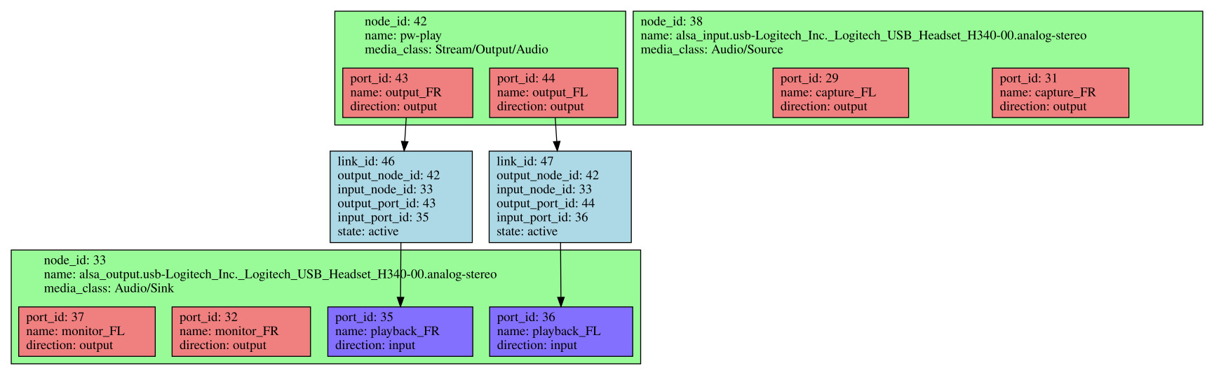
pw-dot, called without any argument, will generate a pw.dot file that represents the active nodes, their ports and the links in the current graph. A .dot file is a textual description of a graph which can be turned graphical using a tool from the Graphviz project. It is simpler to install Graphviz on your host PC, using your favorite package manager, and copy the pw.dot file from the target to the host (a simple local copy as we are using an NFS root filesystem). A SVG file can then be generated as such:
dot -Tsvg pw.dot > pw.svg
Here is what the graph looks like when audio is being outputted using a single source:
PipeWire graph generated by pw-dot, click to see in full size
Conclusion
We have managed to create a rather bare image, with WirePlumber monitoring ALSA devices and adding them as devices and nodes to the PipeWire graph. WirePlumber automatically creates links between source nodes and the default sink node, which means that audio is outputted.
The next step is to create our own custom PipeWire source node. We’ll be able to use the PipeWire API through libpipewire and see what information and capabilities it exposes relative to the overall graph.
Back in December 2021, we had announced the buildroot-external-st project, which is an extension of the Buildroot build system with ready-to-use configurations for the STMicroelectronics STM32MP1 platforms.
More specifically, this project is a BR2_EXTERNAL repository for Buildroot, with a number of defconfigs that allows to quickly build embedded Linux systems for the STM32MP1 Discovery Kit platforms. It’s a great way to get started with Buildroot on those platforms.
Today, we are happy to announce an updated version of this project, published under the branch st/2022.02 at https://github.com/bootlin/buildroot-external-st. This new version brings the following changes:
Updated to work with Buildroot 2022.02, the current LTS version of Buildroot
Updated to use the 4.0 “ecosystem” from ST, which means we’re using updated BSP components from ST, namely Linux 5.15, U-Boot 2021.10, TF-A 2.6 and OP-TEE 3.16
New defconfigs have been added to support all variants of the STM32MP157 Discovery Kits: STM32MP157A-DK1 and STM32MP157D-DK1, as well as STM32MP157C-DK2 and STM32MP157F-DK2.
The minimal defconfigs now use OP-TEE as BL32 instead of the minimal monitor provided by TF-A, called SP-MIN
The minimal defconfigs now have mdev enabled, to benefit from automatic kernel module loading
The demo defconfigs now have the Dropbear SSH server enabled
The document available on the Github page details how to use this work, but here is a quick start in just a few steps:
Retrieve Buildroot itself, a branch containing a few patches on top of upstream 2022.02 is needed $ git clone -b st/2022.02 https://github.com/bootlin/buildroot.git
Configure Buildroot, for example here the demo configuration for the STM32MP157F-DK2 $ make BR2_EXTERNAL=../buildroot-external-st st_stm32mp157f_dk2_demo_defconfig
Run the build $ make
Flash the resulting SD card image available at output/images/sdcard.img and boot your board!
If you have any question or issue, feel free to use the Github issue tracker to contact us. Bootlin is an ST Authorized Partner, and can provide engineering and training services around embedded Linux on STM32MP1 platforms.
Flutter is an open source UI framework, released in 2017 by Google, that allows the creation of multi-platform applications, without having to worry about constraints related to supported platforms.
Flutter applications are written in a programming language called Dart, then compiled and run as a native applications, to be efficiently executed on Linux, Android, iOS or Windows platforms, but also as Web applications.
On Linux platforms, Flutter can be used on top of several graphic back-ends:
DRM
Wayland
X11
Flutter is composed of four main parts:
the embedder (C++, Java…): the glue for specific platforms that provides surface rendering, vsync.
the engine (C/C++): the graphic engine based on Skia, that provides asset resolution, graphics shell, Dart VM…
the framework (Dart): to create UI by using widgets, animation…
the applications (Dart)
In this article, we show how to build a custom Linux distribution that includes a Flutter Embedder that uses the DRM/EGLStream backend, in order to run the Flutter Gallery application on the NVIDIA Tegra Xavier NX platform.
In addition, we will also extend a Yocto SDK to embed the Flutter toolchain, to be able to build Flutter applications directly with the SDK.
Configure Yocto and build an image
To build our Flutter-enabled Linux distribution, we have chosen to use OpenEmbedded, driven through the Kas utility. Kas is a tool developed by Siemens to facilitate the setup of projects based on Bitbake, such as OpenEmbedded or Yocto.
Kas relies on a YAML file that indicates the information required to:
clone bitbake and required layers
configure the build environment
launch bitbake process
Below is the Kas YAML file that we created for this example:
The meta-flutter layer, which contains all the Flutter related recipes
The meta-tegra layer, which is our BSP layer containing all the bootloader/kernel and machine-specific recipes for the Nvidia Jetson Xavier NX platform
The meta-clang layer, which is needed by the meta-flutter layer, as Flutter is built using the Clang compiler
As we chose to use a DRM/EGLStream backend of Flutter we extend the DISTRO_FEATURES to enable the support of OpenGL and Wayland:
DISTRO_FEATURES:append = " opengl wayland"
In addition, we extend the list of packages that will be installed in the image with the ones that provide the Flutter embedder and the Gallery application:
Finally, we also install the package that provides a configuration to set the correct modeset when the Tegra direct rendering module is probed.
IMAGE_INSTALL:append = " tegra-udrm-probeconf"
Using this YAML file, we can instruct Kas to launch the build:
kas build kas-flutter-example.yml
Storage flash process
Images and Nvidia tools to flash Jetson platforms are packaged into a tarball built and deployed as a target image into the folder build/tmp-glibc/deploy/images.
The SD card image for the Jetson Xavier NX can be flashed in two different ways:
from the target board,
from the host.
Here, we explain how to flash it from the target board.
Note: Each Jetson model has its own particular storage layout.
First, we need to extract the tegraflash archive:
mkdir tegraflash
cd tegraflash
tar -xvzf ../build/tmp-glibc/deploy/images/jetson-xavier-nx-devkit/core-image-minimal-jetson-xavier-nx-devkit.tegraflash.tar.gz
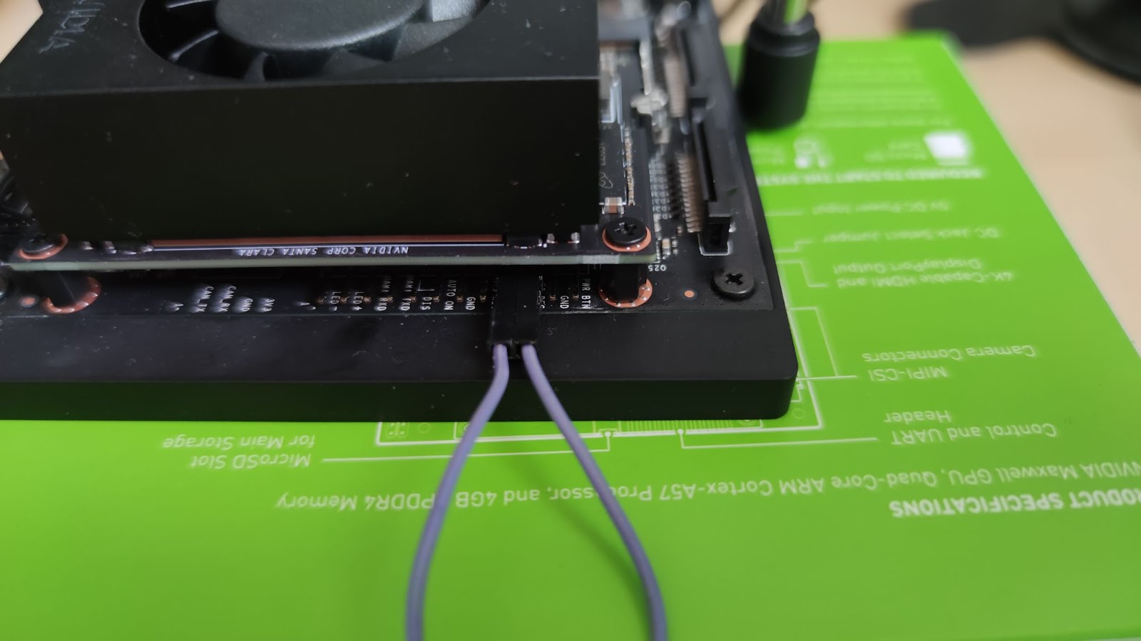
Moreover, to be able to flash the Jetson Xavier NX, it is required to switch it in recovery mode. For that it is necessary to connect a jumper between the 3rd and 4th pins from the right hand side of the “button header” underneath the back of the module (FRC and GND; see the labeling on the underside of the carrier board).
With this done, the module will power up in recovery mode automatically and will be visible from the host PC as an additional USB device:
lsusb |egrep 0955
Bus 003 Device 047: ID 0955:7e19 NVIDIA Corp.
Overall, here are the steps to follow to flash the SD card and the SPI Nand:
Start with your Jetson powered off.
Enable the recovery mode, as indicated above.
Connect the USB cable from your Jetson to your development host.
Insert an SD card into the slot on the module.
Power on the Jetson and put it into recovery mode.
Execute ./doflash.sh from the extracted tegraflash archive.
Finally, the target will boot.
Launch the Flutter application
Now, it is possible to start the Flutter Gallery application which is part of the core-image-minimal image, together with the Flutter stack, with the following command:
The OpenEmbedded build system can also be used to generate an application development SDK, that is a self-extracting tarball containing a cross-development toolchain, libraries and headers. This allows application developers to build, deploy and debug applications without having to do the OpenEmbedded build themselves.
It is possible to enrich the SDK’s sysroots with additional packages, through the variables TOOLCHAIN_HOST_TASK and TOOLCHAIN_TARGET_TASK.
That allows for example to extend the SDK with for example profiling tools, debug tools, symbols to be able to debug offline.
So, we used these variables to append the Flutter SDK and required dependencies to the Yocto SDK, to be able to cross-build Flutter applications with it.
To use the SDK, it is required to source the environment setup script that will set some cross-compile variables, like CC, LD, GDB, in the shell environment to develop or debug applications with SDK’s sysroots:
To illustrate how to use the SDK, let’s see how to build the Gallery Flutter application with the Yocto SDK. Before calling the flutter command, the SDK environment-setup script has been sourced and the following environment variables have been set:
FLUTTER_SDK: the path to the Flutter SDK into the Yocto SDK,
ENGINE_SDK: where the Flutter engine shall be built,
PATH: to extend the shell environment with Flutter tools provided by the SDK.
We can then retrieve the application source code:
git clone git@github.com:flutter/gallery.git
cd gallery
git checkout 9eb785cb997ff56c46e933c1c591f0a6f31454f6
Here, it is a workaround, that allows the flutter command line to correctly find the version of Flutter SDK:
Without the workaround above, the following error is raised:
The current Flutter SDK version is 0.0.0-unknown.
[...]
Failed to find the latest git commit date: VersionCheckError: Command exited with code 128: git -c log.showSignature=false log -n 1 --pretty=format:%ad --date=iso
Standard out:
Standard error: error: object directory build/downloads/git2/github.com.flutter.flutter.git/objects does not exist; check .git/objects/info/alternates
fatal: bad object HEAD
Returning 1970-01-01 01:00:00.000 instead.
[...]
Set the required environment variables and build the application for Linux:
export FLUTTER_SDK="${destination}/sysroots/x86_64-oesdk-linux/usr/share/flutter/sdk"
export PATH=${FLUTTER_SDK}/bin:$PATH
export ENGINE_SDK="./engine_sdk/sdk"

flutter config --enable-linux-desktop
flutter doctor -v
flutter build linux --release
flutter build bundle
This gives you the Flutter application, ready to run on the target!
Conclusion
In this blog post, we have shown that deploying Flutter on an OpenEmbedded distribution was a relatively easy process, and that the SDK can be extended to allow building Flutter applications.
 Bootlin is really happy to welcome another engineer in its team: Jérémie Dautheribes, who joined us on November 2, 2022.
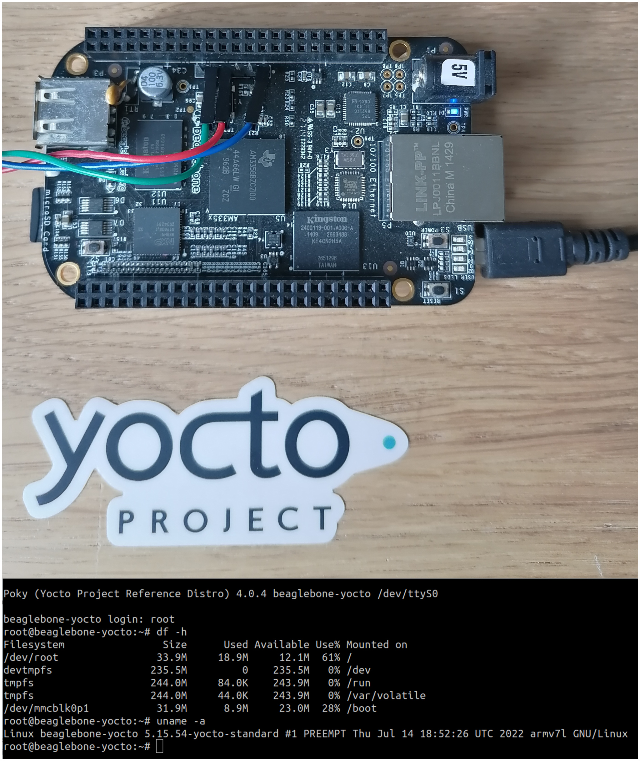
 The
The