After showing how to build and run a minimal Linux system for the STM32MP157 Discovery board in a previous blog post, we are now going to see how to connect an I2C sensor, adjust the Device Tree to enable the I2C bus and I2C device, and how to adjust the kernel configuration to enable the appropriate kernel driver.
List of articles in this series:
- Building a Linux system for the STM32MP1: basic system
- Building a Linux system for the STM32MP1: connecting an I2C sensor
- Building a Linux system for the STM32MP1: enabling Qt5 for graphical applications
- Building a Linux system for the STM32MP1: setting up a Qt5 application development environment
- Building a Linux system for the STM32MP1: developing a Qt5 graphical application
- Building a Linux system for the STM32MP1: implementing factory flashing
- Building a Linux system for the STM32MP1: remote firmware updates
Choosing an I2C sensor
 For this project, we wanted an I2C sensor that was at least capable of measuring the temperature, so we simply started by searching i2c temperature sensor on Amazon. After a bit of research, we found that the BME280 sensor from Bosch was available on several inexpensive break-out boards, and it already had a device driver in the upstream Linux kernel. When choosing hardware, it is always important to check whether it is already supported or not in the upstream Linux kernel. Having a driver already integrated in the upstream Linux kernel has a number of advantages:
- The driver is readily available, you don’t have to integrate a vendor-provided driver, with all the possible integration issues
- The driver has been reviewed by the Linux kernel maintainers, so you can be pretty confident of the code quality
- The driver is using standard Linux interfaces, and not some vendor-specific one
- The driver will be maintained in the long run by the kernel community, so you can continue to update your Linux kernel to benefit from security updates, bug fixes and new features
In addition, it also turns out that the BME280 sensor not only provides temperature sensing, but also pressure and humidity, which makes it even more interesting.
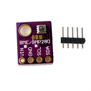
Among the numerous inexpensive BME280 break-out boards, we have chosen specifically this one, but plenty of others are available. The following details will work with any other BME280-based break-out board.
Connecting the I2C sensor
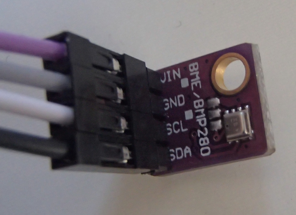
From a connectivity point of view, our I2C sensor is pretty simple: a VIN signal for power, a GND signal for ground, a SCL for the I2C clock and a SDA for the I2C data.
To understand how to connect this sensor to the Discovery board, we need to start with the board user manual.
The Discovery board has two main expansion connectors: CN2 and the Arduino connectors.
Connector CN2
Connector CN2 is a 40-pin male header on the front side of the board:
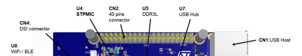
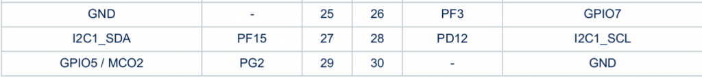
Section 7.17 of the board user manual documents the pin-out of this connector. There is one I2C bus available, through the I2C1_SDA (pin 27) and I2C1_SCL (pin 28) signals.
Arduino connectors
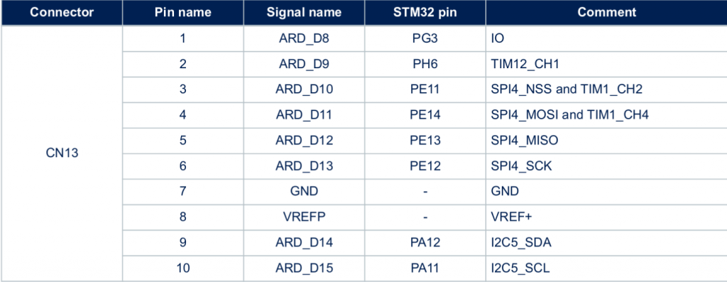
Connectors CN13, CN14, CN16, CN17 are female connectors on the back side of the board. They are compatible in pin-out and form-factor with the Arduino connector:
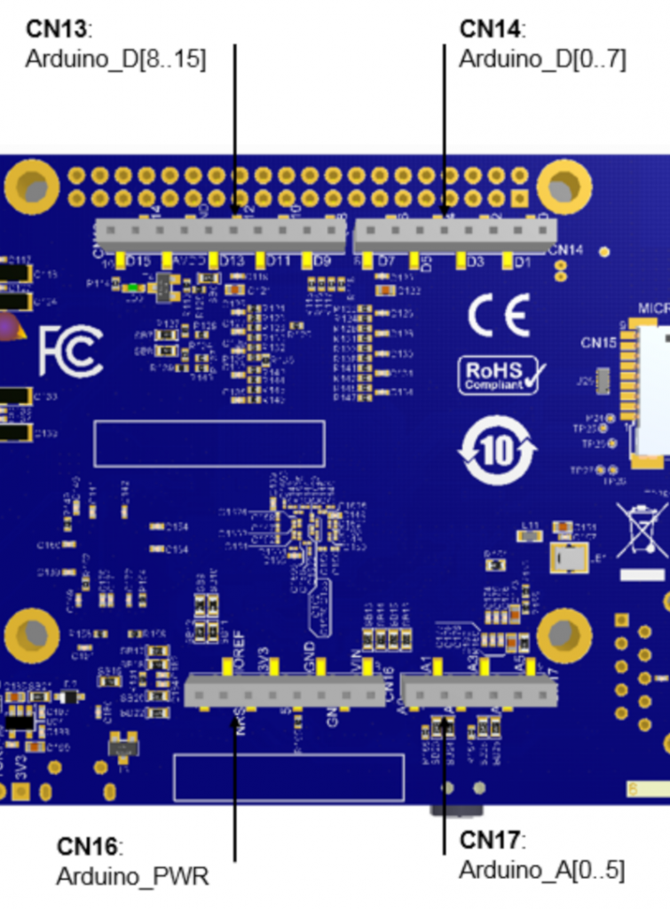
Section 7.16 of the board user manual documents the pin-out for these connectors. There is one I2C bus available as well in CN13, through the I2C5_SDA (pin 9) and I2C5_SCL (pin 10) signals.
Choosing the connector
According to the block diagram in Figure 3 of the board user manual, the I2C1 bus is already used to connect the touchscreen, the USB hub, the audio codec and the HDMI transceiver. However, I2C5 doesn’t seem to be used at all. In addition, with the screen mounted on the Discovery board, the CN2 connector is beneath the screen, which makes it a bit more difficult to use than the Arduino connectors on the back side.
We will therefore use the I2C5 bus, through the Arduino connector CN13. Pin 9 will be used to connect the data signal of our sensor, and pin 10 will be used to connect the clock signal of our sensor.
Finalizing the connectivity
We still have to find out how to connect the VIN and GND pins. According to the BME280 datasheet, VDDmain supply voltage range: 1.71V to 3.6V. The Arduino connector CN16 provides either 3.3V or 5V, so we’ll chose 3.3V (pin 4). And this connector also has multiple ground pins, among which we will chose pin 6.
Overall, this gives us the following connections:
| Sensor signal | Arduino connector | Pin |
| VIN | CN16 | pin 4 |
| GND | CN16 | pin 6 |
| SDA | CN13 | pin 9 |
| SCL | CN13 | pin 10 |
Here are a few pictures of the setup. First, on the sensor side, we have a purple wire for VIN, a grey wire for GND, a white wire for SCL and a black wire for SDA:
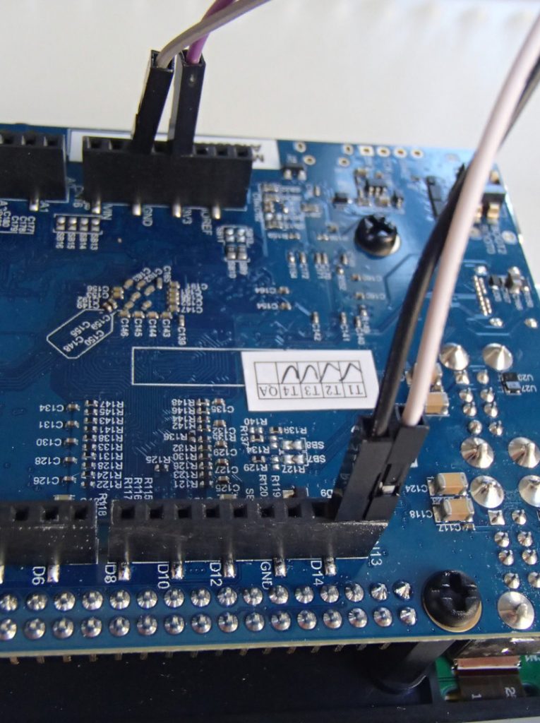
On the board side, we can see the purple wire (VIN) going to pin 4 of CN16, the grey wire (GND) going to pin 6 of CN16, the white wire (SCL) going to pin 10 of CN13 and the black wire (SDA) going to pin 9 of CN13.
With this we’re now all set in terms of hardware setup, let’s move on to enabling the I2C bus in Linux!
Enabling the I2C bus
An introduction to the Device Tree
In order to enable the I2C bus, we’ll need to modify the Device Tree, so we’ll first need to give a few details about what Device Tree is. If you read again our previous blog post in this series, we already mentioned the Device Tree. As part of the Buildroot build process, a file called stm32mp157c-dk2.dtb is produced, and this file is used at boot time by the Linux kernel: it is the Device Tree.
On most embedded architectures, devices are connected using buses that do not provide any dynamic enumeration capabilities. While buses like USB or PCI provide such capabilities, popular buses used on embedded architectures like memory-mapped buses, I2C, SPI and several others do not allow the operating system to ask the hardware: what peripherals are connected ? what are their characteristics ?. The operating system needs to know which devices are available and what their characteristics are. This is where the Device Tree comes into play: it is a data structure that describes in the form of a tree all the devices that we have in our hardware platform, so that the Linux kernel knows the topology of the hardware.
On ARM platforms, each particular board is described by its own Device Tree file. In our case, the STM32MP157 Discovery Kit 2 is described by the Device Tree file arch/arm/boot/dts/stm32mp157c-dk2.dts in the Linux kernel source code. This human-readable source file, with a .dts extension, is compiled during the Linux kernel build process into a machine-readable binary file, with a .dtb extension.
This stm32mp157c-dk2.dts describes the hardware of our Discovery Kit 2 platform. In fact, it only describes what is specific to the Discovery Kit 2: the display panel, the touchscreen, the WiFi and Bluetooth chip. Everything else is common with the Discovery Kit 1 platform, which is why the stm32mp157c-dk2.dts file includes the arm/boot/dts/stm32mp157a-dk1.dts file. Indeed, stm32mp157a-dk1.dts describes the hardware on the Discovery Kit 1, which is the same as the Discovery Kit 2, without the display, touchscreen and WiFi/Bluetooth chip.
In turn, the stm32mp157a-dk1.dts includes three other Device Tree files:
- arm/boot/dts/stm32mp157c.dtsi, which describes all the devices inside the STM32MP157 system-on-chip. It will be used by all Device Tree files describing boards based on the STM32MP157 processor.
- arm/boot/dts/stm32mp157c-m4-srm.dtsi, which describes the Cortex-M4 resources, which we are not going to discuss further for the moment
- arm/boot/dts/stm32mp157cac-pinctrl.dtsi, which provides some pin-muxing related details, which are specific to the SoC package being used.
At this point, we won’t give much more generic details about the Device Tree, as it’s an entire topic on its own. For additional details, you could check the Device Tree for Dummies presentation from your author (slides, video) or the devicetree.org web site.
I2C controllers in the Device Tree
Zooming in to the topic of I2C, we can see that arm/boot/dts/stm32mp157c.dtsi describes 6 I2C controllers through six different nodes in the Device Tree:
i2c1: i2c@40012000i2c2: i2c@40013000i2c3: i2c@40014000i2c4: i2c@5c002000i2c5: i2c@40015000i2c6: i2c@5c009000
This list of six I2C controllers nice matches the list of I2C controllers in the STM32MP157 datasheet, and their base address in the memory map, section 2.5.2:
![]()
![]()
![]()
![]()
![]()
![]()
In the file arm/boot/dts/stm32mp157a-dk1.dts, we can see that the I2C1 bus is enabled, and that a cs42l51 audio codec (I2C address 0x4a) and a sii9022 HDMI transceiver (I2C address 0x39) are connected to it:
&i2c1 {
	status = "okay";

	cs42l51: cs42l51@4a {
		compatible = "cirrus,cs42l51";
		reg = <0x4a>;
	};

	hdmi-transmitter@39 {
		compatible = "sil,sii9022";
		reg = <0x39>;
	};
};
Also, on the I2C4 bus, we can see the USB-C controller (I2C address 0x28) and the PMIC (I2C address 0x33):
&i2c4 {
	status = "okay";

	typec: stusb1600@28 {
		compatible = "st,stusb1600";
		reg = <0x28>;
	};

	pmic: stpmic@33 {
		compatible = "st,stpmic1";
		reg = <0x33>;
	};
};
So, to enable our I2C5 bus, we will simply need to add:
&i2c5 {
	status = "okay";
	clock-frequency = <100000>;
	pinctrl-names = "default", "sleep";
	pinctrl-0 = <&i2c5_pins_a>;
	pinctrl-1 = <&i2c5_pins_sleep_a>;
};
to enable the bus. This piece of code adds the following Device Tree properties to the I2C5 Device Tree node:
status = "okay"which simply tells the Linux kernel: I really intend to use this device, so please enable whatever driver is needed to use this deviceclock-frequency = <100000>tells Linux at which frequency we want to operate the I2C bus: in this case, 100 kHz- The
pinctrlproperties configure the pin muxing, so that the pins are configured in the I2C function when the system is running (thedefaultstate) and into a different state to preserve power when the system is in suspend to RAM (sleepstate). Bothi2c5_pins_aandi2c5_pins_sleep_aare already defined in arch/arm/boot/dts/stm32mp157-pinctrl.dtsi.
For now, this doesn’t describe any device on the bus, but should be sufficient to have the bus enabled in Linux. The question now is how to make this modification in our Device Tree in the proper way ?
Changing the Linux kernel source code
When Buildroot builds each package, it extracts its source code in output/build/<package>-<version>, so the source code of our Linux kernel has been extracted in output/build/linux-custom/. One could therefore be tempted to make his code changes directory in output/build/linux-custom/, but this has a number of major drawbacks:
output/build/linux-custom/is not under version control: it is not part of a Linux kernel Git repository, so you can’t version control your changes, which is really not greatoutput/build/linux-custom/is a temporary folder: if you do amake cleanin Buildroot, this folder will be entirely removed, and re-created during the next Buildroot build
So, while doing a change directly in output/build/linux-custom/ is perfectly fine for quick/temporary changes, it’s not a good option to make changes that will be permanent.
To do this in a proper way, we will use a feature of Buildroot called pkg_OVERRIDE_SRCDIR, which is documented in section 8.12.6 Using Buildroot during development of the Buildroot manual. This feature allows to tell Buildroot: for a given package, please don’t download it from the usual location, but instead take the source code from a specific location on my system. This specific location will of course be under version control, and located outside of Buildroot, which allows to solve the two issues mentioned above.
So, let’s get set this up for the Linux kernel source code:
- Start in the parent folder of Buildroot, so that the Linux kernel source code ends up being side-by-side with Buildroot
- Clone the official upstream Linux kernel repository. Even though we could directly clone the STMicro Linux kernel repository, your author always finds it nicer to have the
originGit remote set up to the official upstream Git repository.git clone git://git.kernel.org/pub/scm/linux/kernel/git/torvalds/linux.git
- Move inside this Git repository
cd linux/
- Add the STMicro Linux kernel repository as a remote:
git remote add stmicro https://github.com/STMicroelectronics/linux.git
- Fetch all the changes from the STMicro Linux kernel repository:
git fetch stmicro
- Create a new branch, called
bme280, based on the tagv4.19-stm32mp-r1.2. This tag is the one used by our Buildroot configuration as the version of the Linux kernel. The following command also moves to this new branch as the same time:git checkout -b bme280 v4.19-stm32mp-r1.2
- The I2C busses:
i2c-0,i2c-1,i2c-2andi2c-3. It is worth mentioning that the bus numbers do not match the datasheet: they are simply numbered from 0 to N. However, thei2c-0symbolic link shows it’s the I2C controller at base address0x40012000, so it’s I2C1 in the datasheet,i2c-1is at base address0x40015000so it’s I2C5 in the datasheet, andi2c-2at base address0x5c002000is I2C4 in the datasheet.i2c-3is special as it’s not an I2C bus provided by the SoC itself, but the I2C bus provided by the HDMI transmitter to talk with the remote HDMI device (since this is unrelated to our discussion, we won’t go into more details on this). - The I2C devices:
0-002a,0-0038,0-0039,0-004a,2-0028,2-033. These entries have the formB-SSSSwhereBis the bus number andSSSSis the I2C address of the device. So you can see that for example0-004acorresponds to the cs42l51 audio codec we mentioned earlier. - Enable the driver in our Linux kernel configuration, so that the driver code gets built as part of our kernel image
- Describe the BME280 device in our Device Tree so that the Linux kernel knows we have one such device, and how it is connected to the system
- /sys/bus/iio/iio:deviceX/, this represents a hardware sensor and groups together the data channels of the same chip.
- /dev/iio:deviceX, character device node interface used for buffered data transfer and for events information retrieval.
- How to connect an I2C sensor to the Discovery board
- What is the Device Tree, and how it is used to describe devices
- How to use Buildroot’s
pkg_OVERRIDE_SRCDIRmechanism - How to enable the I2C bus in the Device Tree and test its operation using
i2cdetectandi2cget - How to change the Linux kernel configuration to enable a new driver
- How to interact using sysfs with a sensor supported by the IIO subsystem
- How to generate a Linux kernel patch, and add it into Buildroot
At this point, our linux/ folder contains the exact same source code as what Buildroot has retrieved. It is time to make our Device Tree change by editing arch/arm/boot/dts/stm32mp157c-dk2.dts and at the end of it, add:
&i2c5 {
	status = "okay";
	clock-frequency = <100000>;
	pinctrl-names = "default", "sleep";
	pinctrl-0 = <&i2c5_pins_a>;
	pinctrl-1 = <&i2c5_pins_sleep_a>;
};
Once done, we need to tell Buildroot to use our kernel source code, using the pkg_OVERRIDE_SRCDIR mechanism. To this, create a file called local.mk, in the top-level Buildroot source directory, which contains:
LINUX_OVERRIDE_SRCDIR = $(TOPDIR)/../linux
This tells Buildroot to pick the Linux kernel source from $(TOPDIR)/../linux. We’ll now ask Buildroot to wipe out its Linux kernel build, and do a build again:
$ make linux-dirclean
$ make
If you look closely at what Buildroot will do, it will do a rsync of the Linux kernel source code from your linux/ Git repository to output/build/linux-custom in Buildroot, and then do the build. You can check output/build/linux-custom/arch/arm/boot/dts/stm32mp157c-dk2.dts to make sure that your I2C5 change is there!
If that is the case, then reflash output/images/sdcard.img on your SD card, and run the new system on the board. It’s now time to test the I2C bus!
Testing the I2C bus
After booting the new system on your Discovery board and logging in as root, let’s have a look at all I2C related devices:
# ls -l /sys/bus/i2c/devices/
total 0
lrwxrwxrwx    0-002a -> ../../../devices/platform/soc/40012000.i2c/i2c-0/0-002a
lrwxrwxrwx    0-0038 -> ../../../devices/platform/soc/40012000.i2c/i2c-0/0-0038
lrwxrwxrwx    0-0039 -> ../../../devices/platform/soc/40012000.i2c/i2c-0/0-0039
lrwxrwxrwx    0-004a -> ../../../devices/platform/soc/40012000.i2c/i2c-0/0-004a
lrwxrwxrwx    2-0028 -> ../../../devices/platform/soc/5c002000.i2c/i2c-2/2-0028
lrwxrwxrwx    2-0033 -> ../../../devices/platform/soc/5c002000.i2c/i2c-2/2-0033
lrwxrwxrwx    i2c-0 -> ../../../devices/platform/soc/40012000.i2c/i2c-0
lrwxrwxrwx    i2c-1 -> ../../../devices/platform/soc/40015000.i2c/i2c-1
lrwxrwxrwx    i2c-2 -> ../../../devices/platform/soc/5c002000.i2c/i2c-2
lrwxrwxrwx    i2c-3 -> ../../../devices/platform/soc/40012000.i2c/i2c-0/i2c-3
This folder is part of the sysfs filesystem, which is used by the Linux kernel to expose to user-space applications all sort of details about the hardware devices connected to the system. More specifically, in this folder, we have symbolic links for two types of devices:
In our case, we are interested by I2C5, which is known by Linux as i2c-1. We will use the i2cdetect utility, provided by Busybox, to probe the different devices on this bus:
# i2cdetect -y 1
     0  1  2  3  4  5  6  7  8  9  a  b  c  d  e  f
00:          -- -- -- -- -- -- -- -- -- -- -- -- --
10: -- -- -- -- -- -- -- -- -- -- -- -- -- -- -- --
20: -- -- -- -- -- -- -- -- -- -- -- -- -- -- -- --
30: -- -- -- -- -- -- -- -- -- -- -- -- -- -- -- --
40: -- -- -- -- -- -- -- -- -- -- -- -- -- -- -- --
50: -- -- -- -- -- -- -- -- -- -- -- -- -- -- -- --
60: -- -- -- -- -- -- -- -- -- -- -- -- -- -- -- --
70: -- -- -- -- -- -- 76 --
Interesting, we have a device at address 0x76! Try to disconnect VIN of your I2C sensor, and repeat the command:
# i2cdetect -y 1
     0  1  2  3  4  5  6  7  8  9  a  b  c  d  e  f
00:          -- -- -- -- -- -- -- -- -- -- -- -- --
10: -- -- -- -- -- -- -- -- -- -- -- -- -- -- -- --
20: -- -- -- -- -- -- -- -- -- -- -- -- -- -- -- --
30: -- -- -- -- -- -- -- -- -- -- -- -- -- -- -- --
40: -- -- -- -- -- -- -- -- -- -- -- -- -- -- -- --
50: -- -- -- -- -- -- -- -- -- -- -- -- -- -- -- --
60: -- -- -- -- -- -- -- -- -- -- -- -- -- -- -- --
70: -- -- -- -- -- -- -- --
The device at 0x76 has disappeared, so it looks like our sensor is at I2C address 0x76. To confirm this, let’s have a look at what the BME280 datasheet says about the I2C address of the device, in section 6.2 I2C Interface:
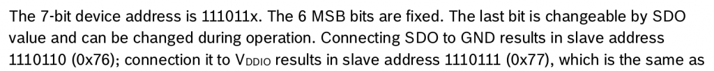
So, the I2C address is indeed 0x76 when the SDO pin of the sensor is connected to GND, which is probably what our BME280 break-out board is doing. It matches the address we have detected with i2cdetect!
Now, let’s talk to our device. According to section 5.4 Register description of the datasheet, there is a Chip ID register, at offset 0xD0 that is supposed to contain 0x60:
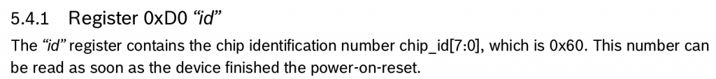
We can read this register using the i2cget command:
# i2cget -y 1 0x76 0xd0
0x60
Good, this matches the expected value according to the BME280 datasheet, so it seems like communication with our I2C device is working, let’s move on to enabling the BME280 sensor driver.
Enabling the sensor driver
As discussed earlier, this BME280 sensor already has a driver in the upstream Linux kernel, in the IIO subsystem. IIO stands for Industrial Input/Output, and this subsystems contains a lot of drivers for various ADCs, sensors and other types of measurement/acquisition devices. In order to use this driver for our BME280 device, we will essentially have to do two things:
Adjusting the kernel configuration
In the previous blog post, we explained that the Linux kernel configuration used to build the kernel for the STM32 Discovery board was located at board/stmicroelectronics/stm32mp157-dk/linux.config. Obviously, we are not going to edit this file manually: we need to run the standard Linux kernel configuration tools.
It turns out that Buildroot has convenient shortcuts to manipulate the Linux kernel configuration. We can run the Linux kernel menuconfig configuration tool by running:
$ make linux-menuconfig
At this point, it is really important to not be confused by the fact that both Buildroot and the Linux kernel use the same configuration utility, but each have its own configuration. The Buildroot configuration describes your overall system (target architecture, which software components you want, which type of filesystem you want, etc.) while the Linux kernel configuration describes the kernel configuration itself (which drivers you want, which kernel features you need, etc.). So make sure to not confuse the menuconfig of Buildroot with the menuconfig of the Linux kernel!
Once you have run make linux-menuconfig, the menuconfig of the Linux kernel will show up. You will then enable the following option:
Device Drivers
+- Industrial I/O support
   +- Pressure sensors
      +- Bosch Sensortec BMP180/BMP280 pressure sensor I2C driver
Make sure to enable this option with a star <*> so that the driver is compiled inside the kernel image itself and not as a separate kernel module. You can then exit the menuconfig utility, and confirm that you want to save the configuration.
At this point, the Linux kernel configuration file in output/build/linux-custom/.config has been changed. You can confirm it by running:
$ grep CONFIG_BMP280 output/build/linux-custom/.config
CONFIG_BMP280=y
CONFIG_BMP280_I2C=y
CONFIG_BMP280_SPI=y
However, as we explained earlier, the output/build/linux-custom/ folder is temporary: it would be removed when doing a Buildroot make clean. We would like to permanently keep our Linux kernel configuration. Once again, Buildroot provides a nice shortcut to do this:
$ make linux-update-defconfig
After running this command, the kernel configuration file board/stmicroelectronics/stm32mp157-dk/linux.config has been updated, and this file is not temporary, and is under version control. If you run git diff, you can see the change on this file:
$ git diff
[...]
index 878a0c39f1..12f3e22647 100644
--- a/board/stmicroelectronics/stm32mp157-dk/linux.config
+++ b/board/stmicroelectronics/stm32mp157-dk/linux.config
@@ -169,6 +169,7 @@ CONFIG_STM32_LPTIMER_CNT=y
 CONFIG_STM32_DAC=y
 CONFIG_IIO_HRTIMER_TRIGGER=y
 CONFIG_IIO_STM32_LPTIMER_TRIGGER=y
+CONFIG_BMP280=y
 CONFIG_PWM=y
 CONFIG_PWM_STM32=y
 CONFIG_PWM_STM32_LP=y
We’re all set for the kernel configuration!
Describing the BME280 in the Device Tree
We now need to tell the Linux kernel that we have a BME280 sensor and how it is connected to the system, which is done by adding more details into our Device Tree. We have already enabled the I2C5 bus, and we now need to describe one device connected to it: this gets done by creating a child node of the I2C controller node.
How do we know what to write in the Device Tree node describing the BME280 ? Using Device Tree bindings. Those bindings are specification documents that describe how a given device should be represented in the Device Tree: which properties are available, what are their possible values, etc. All Device Tree bindings supported by the Linux kernel are documented in Documentation/devicetree/bindings in the Linux kernel source code. For our BME280 device, the binding is at Documentation/devicetree/bindings/iio/pressure/bmp085.yaml.
This document tells us that we have one required property, the compatible property, with the range of possible values. Since we have a BME280 sensor, we’ll use bosch,bme280. The other properties are optional, so we’ll ignore them for now. This binding also documents a reg property, which is used to provide to the Linux kernel the I2C address of the device.
So, we’ll go back to our linux/ directory outside of Buildroot, where we cloned the Linux kernel repository, and we’ll adjust our Device Tree file arch/arm/boot/dts/stm32mp157c-dk2.dts so that it contains:
&i2c5 {
	status = "okay";
	clock-frequency = <100000>;
	pinctrl-names = "default", "sleep";
	pinctrl-0 = <&i2c5_pins_a>;
	pinctrl-1 = <&i2c5_pins_sleep_a>;

	pressure@76 {
		compatible = "bosch,bme280";
		reg = <0x76>;
	};
};
Re-building the kernel
Let’s now ask Buildroot to rebuild the Linux kernel, with our Device Tree change and kernel configuration change. Instead of rebuilding from scratch, we’ll just ask Buildroot to restart the build of the Linux kernel, which will be much faster:
$ make linux-rebuild
As part of this, Buildroot will re-run rsync from our linux/ kernel Git repository to output/build/linux-custom/, so that we really build the latest version of our code, which includes our Device Tree change.
However, this just rebuilds the Linux kernel, and not the complete SD card image, so also run:
$ make
To regenerate the SD card image, write it on your SD card, and boot your system.
Testing the sensor
After booting the system, if we check /sys/bus/i2c/devices, a new entry has appeared:
lrwxrwxrwx 1-0076 -> ../../../devices/platform/soc/40015000.i2c/i2c-1/1-0076
If we following this symbolic link, we can see a number of interesting information:
# ls -l /sys/bus/i2c/devices/1-0076/
total 0
lrwxrwxrwx    driver -> ../../../../../../bus/i2c/drivers/bmp280
drwxr-xr-x    iio:device2
-r--r--r--    modalias
-r--r--r--    name
lrwxrwxrwx    of_node -> ../../../../../../firmware/devicetree/base/soc/i2c@40015000/pressure@76
drwxr-xr-x    power
lrwxrwxrwx    subsystem -> ../../../../../../bus/i2c
-rw-r--r--    uevent
Here we can see that this device is bound with the device driver named bmp280, and that its Device Tree node is base/soc/i2c@40015000/pressure@76.
Now, to actually use the sensor, we need to understand what is the user-space interface provided by IIO devices. The kernel documentation gives some hints:
There are two ways for a user space application to interact with an IIO driver.
So, we’ll try to explore the /sys/bus/iio/ option:
# ls -l /sys/bus/iio/devices/
total 0
lrwxrwxrwx    iio:device0 -> ../../../devices/platform/soc/48003000.adc/48003000.adc:adc@0/iio:device0
lrwxrwxrwx    iio:device1 -> ../../../devices/platform/soc/48003000.adc/48003000.adc:adc@100/iio:device1
lrwxrwxrwx    iio:device2 -> ../../../devices/platform/soc/40015000.i2c/i2c-1/1-0076/iio:device2
lrwxrwxrwx    iio:device3 -> ../../../devices/platform/soc/48003000.adc/48003000.adc:temp/iio:device3
lrwxrwxrwx    trigger0 -> ../../../devices/platform/soc/40004000.timer/trigger0
Here we can see a number of IIO devices: our IIO device is iio:device2, as can be seen by looking at the target of the symbolic links. The other ones are IIO devices related to the ADC on the STM32 processor. Let’s check what we have inside /sys/bus/iio/devices/iio:device2/:
# ls -l /sys/bus/iio/devices/iio\:device2/
total 0
-r--r--r--    dev
-rw-r--r--    in_humidityrelative_input
-rw-r--r--    in_humidityrelative_oversampling_ratio
-rw-r--r--    in_pressure_input
-rw-r--r--    in_pressure_oversampling_ratio
-r--r--r--    in_pressure_oversampling_ratio_available
-rw-r--r--    in_temp_input
-rw-r--r--    in_temp_oversampling_ratio
-r--r--r--    in_temp_oversampling_ratio_available
-r--r--r--    name
lrwxrwxrwx    of_node -> ../../../../../../../firmware/devicetree/base/soc/i2c@40015000/pressure@76
drwxr-xr-x    power
lrwxrwxrwx    subsystem -> ../../../../../../../bus/iio
-rw-r--r--    uevent
This is becoming interesting! We have a number of files that we can read to get the humidity, pressure, and temperature:
# cat /sys/bus/iio/devices/iio\:device2/in_humidityrelative_input
49147
# cat /sys/bus/iio/devices/iio\:device2/in_pressure_input
101.567167968
# cat /sys/bus/iio/devices/iio\:device2/in_temp_input
24380
Now, let’s check the kernel documentation at Documentation/ABI/testing/sysfs-bus-iio to understand the units used in these files:
What:		/sys/bus/iio/devices/iio:deviceX/in_tempX_input
Description:
		Scaled temperature measurement in milli degrees Celsius.

What:		/sys/bus/iio/devices/iio:deviceX/in_pressure_input
Description:
		Scaled pressure measurement from channel Y, in kilopascal.

What:		/sys/bus/iio/devices/iio:deviceX/in_humidityrelative_input
Description:
		Scaled humidity measurement in milli percent.
So here we are: we are able to read the data from our sensor, and the Linux kernel driver does all the conversion work to convert the raw values from the sensors into usable values in meaningful units.
Turning our kernel change into a patch
Our Device Tree change is for now only located in our local Linux kernel Git repository: if another person builds our Buildroot configuration, he won’t have access to this Linux kernel Git repository, which Buildroot knows about thanks to the LINUX_OVERRIDE_SRCDIR variable. So what we’ll do now is to generate a Linux kernel patch that contains our Device Tree change, add it to Buildroot, and ask Buildroot to apply it when building the Linux kernel. Let’s get started.
First, go in your Linux kernel Git repository in linux/, review your Device Tree change with git diff, and if everything is alright, make a commit out of it:
$ git commit -as -m "ARM: dts: add support for BME280 sensor on STM32MP157 DK2"
Then, generate a patch out of this commit:
$ git format-patch HEAD^
This will create a file called 0001-ARM-dts-add-support-for-BME280-sensor-on-STM32MP157-.patch that contains our Device Tree change.
Now, back in Buildroot in the buildroot/ folder, create the board/stmicroelectronics/stm32mp157-dk/patches/ folder and a sub-directory board/stmicroelectronics/stm32mp157-dk/patches/linux. Copy the patch into this folder, so that the file hierarchy looks like this:
$ tree board/stmicroelectronics/stm32mp157-dk/
board/stmicroelectronics/stm32mp157-dk/
├── genimage.cfg
├── linux.config
├── overlay
│   └── boot
│       └── extlinux
│           └── extlinux.conf
├── patches
│   └── linux
│       └── 0001-ARM-dts-add-support-for-BME280-sensor-on-STM32MP157-.patch
├── readme.txt
└── uboot-fragment.config
Now, run Buildroot’s menuconfig:
$ make menuconfig
And in Build options, set global patch directories to the value board/stmicroelectronics/stm32mp157-dk/patches/. This tells Buildroot to apply patches located in this folder whenever building packages. This way, when the linux package will be built, our patch in board/stmicroelectronics/stm32mp157-dk/patches/linux/ will be applied.
We can now remove the local.mk file to disable the pkg_OVERRIDE_SRCDIR mechanism, and ask Buildroot to rebuild the Linux kernel:
$ rm local.mk
$ make linux-dirclean
$ make
If you pay attention to the Linux kernel build process, you will see that during the Patching step, our Device Tree patch gets applied:
>>> linux custom Patching

Applying 0001-ARM-dts-add-support-for-BME280-sensor-on-STM32MP157-.patch using patch:
patching file arch/arm/boot/dts/stm32mp157c-dk2.dts
You can of course reflash the SD card at the end of the build, and verify that everything still works as expected.
Let’s save our Buildroot configuration change:
$ make savedefconfig
And commit our Buildroot changes:
$ git add board/stmicroelectronics/stm32mp157-dk/linux.config
$ git add board/stmicroelectronics/stm32mp157-dk/patches/
$ git add configs/stm32mp157_dk_defconfig
$ git commit -s -m "configs/stm32mp157_dk: enable support for BME280 sensor"
We can now share our Buildroot change with others: they can build our improved system which has support for the BME280 sensor.
Conclusion
You can find the exact Buildroot source code used to reproduce the system used in this article in the branch at 2019.02/stm32mp157-dk-blog-2.
In this article, we have learned a lot of things:
In our next article, we’ll look at adding support for the Qt5 graphical library into our system, as a preparation to developing a Qt5 application that will display our sensor measurements on the Discovery board screen.
Many thanks for your article. This is very useful for understanding embedded Linux for me. So much information in one place.
Many thanks for this, this is really useful. One question though, is it necessary to set pinctrl settings for the i2c5? I don’t see it for the other I2Cs.
thank you very much. I will develop a demo industrial project on stm32mp157c-dk2 for my master thesis. Can I also connect a 12v fan (vantilator) to this board? Can you please write an article on it ?
Or Could you please tell me what sensors or actors can be tried to connect ? (as far as you know)
You cannot connect a 12V fan directly, the board only provides 5V/3.3V power rails and I/Os. You’ll have to use a relay or some other technology.
You can connect any sensor or actuators that communicates over I2C, SPI, 1-wire, UART, and have voltage levels compatible with the STM32MP157-DK2 board.
Great blog. I really enjoy it. It is great to get started with the stm32mp1 without the packages from ST and build an own application.
Small annotation: the command “LINUX_OVERRIDE_SOURCE = $(TOPDIR)/../linux” did not work for me. Should it be “LINUX_OVERRIDE_SRCDIR = $(TOPDIR)/../linux” instead?
I am looking forward for more posts 😀
Well spotted for the SOURCE -> SRCDIR typo, I fixed it. Thanks!
Hello,
I will read the same sensor from M4 side, not from linux side. Is it necessary for me to enable I2C in device tree ?
how can I read bme280 from M4 side ? Should I analyze i2c example for M4 in offical package and modify it in System workbench (eclipse based tool for developing) and deploy it ?
Is that all ?
Do I have to do also something with stm32cubemx or some another tool ?
Thanks Mark for your question. We have not yet looked at using the M4 to read the sensor, but it is actually something we are considering for a next part of our series of blog post, so stay tuned!
Hello,
I tried connecting an st pressure sensor via i2c.
It all works perfectly fine until I want to apply the driver. (I see the device in the list and get a valid response with i2cget).
but unfortunately I cannot read any values as it seems the driver is not applied to the device.
I used a “compatible” string from the st-sensors.txt and added the right address.
but no success.
any idea whats wrong? thanks in advance.
Hello Niklas. Unfortunately, you don’t provide enough details to allow us to help. Could you contact us at info@bootlin.com so that we can discuss your issue ?
Great article!
I have one question: how can I turn on a possibility of using command “apt-get install” on the MP1? I want using “minicom” for listening UART ports 🙂
Hi
We’re talking about Buildroot here. There are no such things are packages in Buildroot, and installing “apt” to fetch packages from unrelated distributions won’t work (different C library, etc).
All you need to do is fire Buildroot again to add the extra software components you need.
Cheers,
Michael.
Hi Thomas,
thank you very much for the great article.
I learned really a lot from reading it!
It seems that you changed the file Format from txt. to yaml
(Link broken: Documentation/devicetree/bindings/iio/pressure/bmp085.txt)
Hello Bjoern, thanks for your comment, glad to hear the article was useful. The Device Tree binding file name was not changed by us, but by the upstream Linux kernel developers. I’ve updated the link in the article to point to the new Device Tree binding document, and also changed a bit the text about it to reflect changes in this Device Tree binding description. Thanks!
Great tutorial. Especially the patch instructions!
I had a couple of issues:
1) Did you really mean stm32mp157_dk_defconfig? Or was it supposed to be stm32mp157c_dk2_defconfig (or even stm32mp157a_dk1_defconfig)? I assume a typo?
2) Also after removing local.mk I had to update the buildroot kernel config to point to the stmlinux and not the mainline linux:
BR2_LINUX_KERNEL_CUSTOM_GIT=y
BR2_LINUX_KERNEL_CUSTOM_REPO_URL=”https://github.com/STMicroelectronics/linux”
BR2_LINUX_KERNEL_CUSTOM_REPO_VERSION=”v4.19-stm32mp-r1.3″
Thanks for your comment!
(1) was not a typo. My blog post is based on what I pushed at https://github.com/tpetazzoni/buildroot/tree/2019.02/stm32mp157-dk-blog-7, which was then based on Buildroot 2019.02. Since then, many Buildroot releases have been published, and upstream support was added for the DK1/DK2. If you look at my older Buildroot branch, which is documented in this series of blog posts, the defconfig name is really stm32mp157_dk_defconfig. But if you look at the current upstream Buildroot, there are indeed two separate defconfigs for DK1 and DK2.
(2) this is again because you are using the upstream Buildroot (which is good!) and not the older branch that I had published for this series of blog posts. My older branch was based on the Linux kernel from the ST Github repository, while the defconfigs in upstream Buildroot are using the upstream Linux kernel.
Merci pour ce tutoriel Mr Thomas. Jusqu’à quand peut-ont s inscrire à votre séminaire en mars?J’aimerais bien y participer.
Bonjour Nickdann. Pourriez-vous préciser à quel séminaire vous faites référence ? Toutes nos formations en ligne sont listées sur https://bootlin.com/training/. Sous réserve de places disponibles, vous pouvez vous inscrire jusqu’au dernier moment, c’est à dire le jour même du début de la formation.
Hi!
I’m very new to Linux embedded topics, started now to explore BuildRoot and Yocto, and Bootlin tutorials have been really precious so far.
While following the steps of this article, I wanted to use the kernel provided by ST with their Developer Package (which I already built and verified that works fine with ST image). So I make pkg_OVERRIDE_SRCDIR feature to point to such kernel sources. It seems everything builds successfully, but when I try to boot the STM32MP157C-DK2 then it gets stuck at “Starting kernel…”.
I just wanted to ask, does it smell like some common newbie mistake and you could point me to some direction, or should I dig further into enabling more logging/debugging?
The same issue if I do exactly as described in this article, cloning the official kernel repo then fetching the STMicro Linux kernel repository.
But it works if I point to the copy of kernel 5.8.13 I made when I built the basic Linux system described in the very first article of this series.
Hello Michele. Make sure you are using matching versions of the entire low-level software stack: TF-A, U-Boot and the Linux kernel. For example, if you use the latest 5.10 kernel provided by ST, you also need to use the matching version of TF-A and U-Boot. And obviously, use the Device Tree provided by this 5.10 kernel.
Thank you Thomas,
Indeed I was doing something wrong there, I managed to move some step forward but didn’t get it to work yet.
I post here my experience, but feel free to delete if it’s off topic for this blog article.
Using menuconfig I point Kernel, TF-A and U-boot to the latest label releases of ST forked repos. But it did not work because it asked for FIP image.
I enabled FIP image using menuconfig, but building fails. After investigating a bit, I realized Buildroot is missing a value for the variable BL33_CFG, which from some documentation I understand it should be set to the U-Boot device tree binary.
Looking at the code and makefiles I couldn’t find a properly supported pattern for this, so I have made few changes: Buildroot to copy u-boot.dtb to the output folder, and set from menuconfig an additional variable for ARM_TRUSTED_FIRMARE:
BL33_CFG=$(BINARIES_DIR)/u-boot.dtb.
Now building succeed without issues apparently.
The next step would be to flash using STM32CubeProgrammer, I use this tsv file:
———–
#Opt Id Name Type IP Offset Binary
– 0x01 fsbl1-boot Binary none 0x0 tf-a-stm32mp157c-dk2.stm32
– 0x03 fip-boot Binary none 0x0 fip.bin
P 0x04 fsbl1 Binary mmc0 0x00004400 tf-a-stm32mp157c-dk2.stm32
P 0x05 fsbl2 Binary mmc0 0x00044400 tf-a-stm32mp157c-dk2.stm32
PD 0x06 fip Binary mmc0 0x00084400 fip.bin
P 0x10 rootfs FileSystem mmc0 0x00484400 rootfs.ext2
———–
But flashing does not go through… after 0x01 and 0x03 the connection should reinitialize, but it never succeed. I started digging more into Buildroot and ST documentation, and I found somewhere mentioned that BL33 should be set to u-boot-nodtb, not u-boot.
I worked this around just making Buildroot to copy u-boot-nodtb.bin to the output folder, and setting in menuconfig:
BR2_TARGET_ARM_TRUSTED_FIRMWARE_UBOOT_BL33_IMAGE=”u-boot-nodtb.bin”
Finally now all the flashing with ST32CubeProgrammer goes through successfully. but when I reboot the board I get:
—————-
NOTICE: CPU: STM32MP157CAC Rev.B
NOTICE: Model: STMicroelectronics STM32MP157C-DK2 Discovery Board
NOTICE: Board: MB1272 Var2.0 Rev.C-01
NOTICE: BL2: v2.4-r1.0(release):2021.02-908-g98bafa68ce-dirty
NOTICE: BL2: Built : 11:41:12, May 2 2021
NOTICE: BL2: Booting BL32
NOTICE: SP_MIN: v2.4-r1.0(release):2021.02-908-g98bafa68ce-dirty
NOTICE: SP_MIN: Built : 11:41:12, May 2 2021
U-Boot 2020.10-stm32mp-r1 (May 02 2021 – 11:40:53 +0300)
CPU: STM32MP157CAC Rev.B
Model: STMicroelectronics STM32MP157C-DK2 Discovery Board
Board: stm32mp1 in trusted mode (st,stm32mp157c-dk2)
Board: MB1272 Var2.0 Rev.C-01
DRAM: 512 MiB
Clocks:
– MPU : 650 MHz
– MCU : 208.878 MHz
– AXI : 266.500 MHz
– PER : 24 MHz
– DDR : 533 MHz
WDT: Started with servicing (32s timeout)
NAND: 0 MiB
MMC: STM32 SD/MMC: 0, STM32 SD/MMC: 1
Loading Environment from MMC… OK
In: serial
Out: serial
Err: serial
Net: eth0: ethernet@5800a000
Hit any key to stop autoboot: 0
Boot over mmc0!
switch to partitions #0, OK
mmc0 is current device
** Unrecognized filesystem type **
STM32MP>
—————
not sure yet how to move forward from here.
Hello Michele. Glad to see you’ve been able to move forward. Indeed, recent versions of TF-A for the STM32MP1 platform have changed to use the FIP image format, which definitely requires adaptation of the Buildroot configuration.
Regarding your current error, U-Boot is probably using the distro bootcmd https://github.com/u-boot/u-boot/blob/master/doc/README.distro, but the filesystem that your SD card (or eMMC ?) uses is not supported by U-Boot.
Hello Thomas,
maybe it was a mistake in the tsv file, after reading the documentation more carefully I noticed that a partition will be marked as bootable only if the type is “System”, not “FileSystem”.
After making this change, U-boot managed to proceed, until I got back to the original issue… it hangs at “Starting Kernel…”
I have then enabled early printk, and started the Kernel from U-boot console, using the following commands:
setenv bootargs ‘rootfstype=ext4 root=PARTUUID=e91c4e10-16e6-4c0e-bd0e-77becf4a3582 rootwait rw earlyprintk console=ttySTM0,115200’
load mmc 0:4 $kernel_addr_r /boot/uImage
load mmc 0:4 $fdt_addr_r /boot/stm32mp157c-dk2.dtb
bootm $kernel_addr_r – $fdt_addr_r
and here is where it stops:
…
…
[ 0.796793] remoteproc remoteproc0: releasing m4
[ 0.802887] ALSA device list:
[ 0.805902] No soundcards found.
[ 0.809403] Warning: unable to open an initial console.
[ 0.814979] Waiting for root device PARTUUID=e91c4e10-16e6-4c0e-bd0e-77becf4a3582…
the partition id should be correct, I got it by running ‘part list mmc 0’ on the U-boot console.
I’m trying now to figure out what could be the issue.
I made it… it took couple of sleepless nights due to my baby-steps into the embedded world, but now it works.
Although the dtb made with Buildroot was exactly the same as the one from ST SDK build, the Kernel log was very different… this turned my focus on the Kernel configuration.
The Kernel settings “Using a custom (def)config file” by default points to the file shipped with Buildroot: board/stmicroelectronics/stm32mp157c-dk2/linux.config.
But can it be this file is outdated? once I replaced with the config used by the official ST SDK then everything started working.
I still don’t like this “blindly replacing files” approach, I might try to dig deeper into such config files to better understand the differences between them. But for now that’s it I guess, thank you very much for the attention and the support!
Hello! Thank you for the informative article. There is a question. I did everything as described in the article,but my board is now constantly rebooting. What could be the matter? Although the download completely passes.
Hard to give very precise/specific advice without more details. When does it reboot? After how much time does it reboot? Have you perhaps enabled the watchdog?
Thomas, thanks! Looks like I turned it off. Now I don’t know how to turn it off. Please tell me how to do this? The reboot time is about 30 seconds. As it is written at startup.
Rather you turned the watchdog on. You need to figure out if it’s U-Boot that turns on the watchdog, or Linux.
Yes, it looks like a watchdog, but how do you know where it is?
The watchdog can either have been enabled by U-Boot or Linux. I would really hope to be more precise, but without reproducing your issue and having more details, it’s very difficult to provide specific help.
Hello, Thomas! Here is the full information on my actions.
My board is STM32MP157A-DK1.
According to the first article, I was unable to start EmbLinux, the device
hung up when loading the kernel.
I tried the advice from the comment in the first lesson from the reader
Michael Opdenackersays:
March 25, 2020 at 7:09 am ”
> git clone git://git.buildroot.net/buildroot
> cd buildroot/
> make stm32mp157a_dk1_defconfig”.
And thanks to this, I managed to start the kernel.
The next thing I did was produce everything that you describe in this tutorial.
But now, after a normal boot, the device restarts
after about 35 seconds of loading.How to find out what is the cause of the reset
Linux kernel or U-boot?
This log…
NOTICE: CPU: STM32MP157AAC Rev.B
NOTICE: Model: STMicroelectronics STM32MP157A-DK1 Discovery Board
NOTICE: Board: MB1272 Var1.0 Rev.C-01
NOTICE: BL2: v2.5(release):2021.08-372-gda8f069d74-dirty
NOTICE: BL2: Built : 12:49:57, Sep 26 2021
NOTICE: BL2: Booting BL32
NOTICE: SP_MIN: v2.5(release):2021.08-372-gda8f069d74-dirty
NOTICE: SP_MIN: Built : 12:49:57, Sep 26 2021
U-Boot 2021.07 (Sep 26 2021 – 12:50:24 +0300)
CPU: STM32MP157AAC Rev.B
Model: STMicroelectronics STM32MP157A-DK1 Discovery Board
Board: stm32mp1 in trusted mode (st,stm32mp157a-dk1)
Board: MB1272 Var1.0 Rev.C-01
DRAM: 512 MiB
Clocks:
– MPU : 650 MHz
– MCU : 208.878 MHz
– AXI : 266.500 MHz
– PER : 24 MHz
– DDR : 533 MHz
WDT: Started with servicing (32s timeout)
NAND: 0 MiB
MMC: STM32 SD/MMC: 0
Loading Environment from MMC… OK
In: serial
Out: serial
Err: serial
invalid MAC address in OTP 00:00:00:00:00:00
Previous ADC measurements was not the one expected, retry in 20ms
****************************************************
* WARNING 500mA power supply detected *
* Current too low, use a 3A power supply! *
****************************************************
Net:
Error: ethernet@5800a000 address not set.
No ethernet found.
Hit any key to stop autoboot: 1 0
Boot over mmc0!
switch to partitions #0, OK
mmc0 is current device
Scanning mmc 0:4…
Found /boot/extlinux/extlinux.conf
Retrieving file: /boot/extlinux/extlinux.conf
131 bytes read in 92 ms (1000 Bytes/s)
1: stm32mp157a-dk1-buildroot
Retrieving file: /boot/zImage
3947848 bytes read in 274 ms (13.7 MiB/s)
append: root=/dev/mmcblk0p4 rootwait
Retrieving file: /boot/stm32mp157a-dk1.dtb
68083 bytes read in 96 ms (692.4 KiB/s)
Kernel image @ 0xc2000000 [ 0x000000 – 0x3c3d48 ]
## Flattened Device Tree blob at c4000000
Booting using the fdt blob at 0xc4000000
ERROR: reserving fdt memory region failed (addr=dc000000 size=4000000)
Loading Device Tree to cffec000, end cffff9f2 … OK
optee optee: OP-TEE api uid mismatch
Starting kernel …
[ 0.000000] Booting Linux on physical CPU 0x0
[ 0.000000] Linux version 4.19.26 (root@vitaly-VirtualBox) (gcc version 10.3.1 20210621 (GNU Toolchain for the A-profile Architecture 10.3-2021.07 (arm-10.29))) #1 SMP PREEMPT Sun Sep 26 12:54:48 MSK 2021
[ 0.000000] CPU: ARMv7 Processor [410fc075] revision 5 (ARMv7), cr=10c5387d
[ 0.000000] CPU: div instructions available: patching division code
[ 0.000000] CPU: PIPT / VIPT nonaliasing data cache, VIPT aliasing instruction cache
[ 0.000000] OF: fdt: Machine model: STMicroelectronics STM32MP157A-DK1 Discovery Board
[ 0.000000] Memory policy: Data cache writealloc
[ 0.000000] Reserved memory: created DMA memory pool at 0x10000000, size 0 MiB
[ 0.000000] OF: reserved mem: initialized node mcuram2@0x10000000, compatible id shared-dma-pool
[ 0.000000] Reserved memory: created DMA memory pool at 0x10040000, size 0 MiB
[ 0.000000] OF: reserved mem: initialized node vdev0vring0@10040000, compatible id shared-dma-pool
[ 0.000000] Reserved memory: created DMA memory pool at 0x10042000, size 0 MiB
[ 0.000000] OF: reserved mem: initialized node vdev0vring1@10042000, compatible id shared-dma-pool
[ 0.000000] Reserved memory: created DMA memory pool at 0x10044000, size 0 MiB
[ 0.000000] OF: reserved mem: initialized node vdev0buffer@10044000, compatible id shared-dma-pool
[ 0.000000] Reserved memory: created DMA memory pool at 0x30000000, size 0 MiB
[ 0.000000] OF: reserved mem: initialized node mcuram@0x30000000, compatible id shared-dma-pool
[ 0.000000] Reserved memory: created DMA memory pool at 0x38000000, size 0 MiB
[ 0.000000] OF: reserved mem: initialized node retram@0x38000000, compatible id shared-dma-pool
[ 0.000000] cma: Reserved 128 MiB at 0xd4000000
[ 0.000000] psci: probing for conduit method from DT.
[ 0.000000] psci: PSCIv1.1 detected in firmware.
[ 0.000000] psci: Using standard PSCI v0.2 function IDs
[ 0.000000] psci: MIGRATE_INFO_TYPE not supported.
[ 0.000000] psci: SMC Calling Convention v1.0
[ 0.000000] random: get_random_bytes called from start_kernel+0x94/0x40c with crng_init=0
[ 0.000000] percpu: Embedded 15 pages/cpu @(ptrval) s30028 r8192 d23220 u61440
[ 0.000000] Built 1 zonelists, mobility grouping on. Total pages: 113792
[ 0.000000] Kernel command line: root=/dev/mmcblk0p4 rootwait
[ 0.000000] Dentry cache hash table entries: 65536 (order: 6, 262144 bytes)
[ 0.000000] Inode-cache hash table entries: 32768 (order: 5, 131072 bytes)
[ 0.000000] Memory: 313440K/458752K available (6144K kernel code, 191K rwdata, 1400K rodata, 1024K init, 165K bss, 14240K reserved, 131072K cma-reserved, 0K highmem)
[ 0.000000] Virtual kernel memory layout:
[ 0.000000] vector : 0xffff0000 – 0xffff1000 ( 4 kB)
[ 0.000000] fixmap : 0xffc00000 – 0xfff00000 (3072 kB)
[ 0.000000] vmalloc : 0xdc800000 – 0xff800000 ( 560 MB)
[ 0.000000] lowmem : 0xc0000000 – 0xdc000000 ( 448 MB)
[ 0.000000] pkmap : 0xbfe00000 – 0xc0000000 ( 2 MB)
[ 0.000000] modules : 0xbf000000 – 0xbfe00000 ( 14 MB)
[ 0.000000] .text : 0x(ptrval) – 0x(ptrval) (7136 kB)
[ 0.000000] .init : 0x(ptrval) – 0x(ptrval) (1024 kB)
[ 0.000000] .data : 0x(ptrval) – 0x(ptrval) ( 192 kB)
[ 0.000000] .bss : 0x(ptrval) – 0x(ptrval) ( 166 kB)
[ 0.000000] SLUB: HWalign=64, Order=0-3, MinObjects=0, CPUs=2, Nodes=1
[ 0.000000] rcu: Preemptible hierarchical RCU implementation.
[ 0.000000] rcu: RCU restricting CPUs from NR_CPUS=4 to nr_cpu_ids=2.
[ 0.000000] Tasks RCU enabled.
[ 0.000000] rcu: Adjusting geometry for rcu_fanout_leaf=16, nr_cpu_ids=2
[ 0.000000] NR_IRQS: 16, nr_irqs: 16, preallocated irqs: 16
[ 0.000000] /soc/interrupt-controller@5000d000: bank0
[ 0.000000] /soc/interrupt-controller@5000d000: bank1
[ 0.000000] /soc/interrupt-controller@5000d000: bank2
[ 0.000000] arch_timer: cp15 timer(s) running at 24.00MHz (virt).
[ 0.000000] clocksource: arch_sys_counter: mask: 0xffffffffffffff max_cycles: 0x588fe9dc0, max_idle_ns: 440795202592 ns
[ 0.000008] sched_clock: 56 bits at 24MHz, resolution 41ns, wraps every 4398046511097ns
[ 0.000026] Switching to timer-based delay loop, resolution 41ns
[ 0.001053] Console: colour dummy device 80×30
[ 0.002232] console [tty0] enabled
[ 0.002280] Calibrating delay loop (skipped), value calculated using timer frequency.. 48.00 BogoMIPS (lpj=240000)
[ 0.002327] pid_max: default: 32768 minimum: 301
[ 0.002536] Mount-cache hash table entries: 1024 (order: 0, 4096 bytes)
[ 0.002574] Mountpoint-cache hash table entries: 1024 (order: 0, 4096 bytes)
[ 0.003223] CPU: Testing write buffer coherency: ok
[ 0.003637] CPU0: update cpu_capacity 1024
[ 0.003676] CPU0: thread -1, cpu 0, socket 0, mpidr 80000000
[ 0.059776] Setting up static identity map for 0xc0100000 – 0xc0100060
[ 0.079759] rcu: Hierarchical SRCU implementation.
[ 0.119840] smp: Bringing up secondary CPUs …
[ 0.200289] CPU1: update cpu_capacity 1024
[ 0.200300] CPU1: thread -1, cpu 1, socket 0, mpidr 80000001
[ 0.200444] smp: Brought up 1 node, 2 CPUs
[ 0.200517] SMP: Total of 2 processors activated (96.00 BogoMIPS).
[ 0.200542] CPU: All CPU(s) started in SVC mode.
[ 0.201507] devtmpfs: initialized
[ 0.224092] VFP support v0.3: implementor 41 architecture 2 part 30 variant 7 rev 5
[ 0.224566] clocksource: jiffies: mask: 0xffffffff max_cycles: 0xffffffff, max_idle_ns: 19112604462750000 ns
[ 0.224629] futex hash table entries: 512 (order: 3, 32768 bytes)
[ 0.230237] pinctrl core: initialized pinctrl subsystem
[ 0.231322] NET: Registered protocol family 16
[ 0.242326] DMA: preallocated 256 KiB pool for atomic coherent allocations
[ 0.245661] stm32-pm-domain pm_domain: domain core-ret-power-domain registered
[ 0.245730] stm32-pm-domain pm_domain: subdomain core-power-domain registered
[ 0.245763] stm32-pm-domain pm_domain: domains probed
[ 0.257927] stm32mp157-pinctrl soc:pin-controller@50002000: GPIOA bank added
[ 0.258245] stm32mp157-pinctrl soc:pin-controller@50002000: GPIOB bank added
[ 0.258509] stm32mp157-pinctrl soc:pin-controller@50002000: GPIOC bank added
[ 0.258756] stm32mp157-pinctrl soc:pin-controller@50002000: GPIOD bank added
[ 0.259023] stm32mp157-pinctrl soc:pin-controller@50002000: GPIOE bank added
[ 0.259273] stm32mp157-pinctrl soc:pin-controller@50002000: GPIOF bank added
[ 0.259511] stm32mp157-pinctrl soc:pin-controller@50002000: GPIOG bank added
[ 0.259745] stm32mp157-pinctrl soc:pin-controller@50002000: GPIOH bank added
[ 0.260000] stm32mp157-pinctrl soc:pin-controller@50002000: GPIOI bank added
[ 0.260140] stm32mp157-pinctrl soc:pin-controller@50002000: Pinctrl STM32 initialized
[ 0.260884] stm32mp157-pinctrl soc:pin-controller-z@54004000: GPIOZ bank added
[ 0.260934] stm32mp157-pinctrl soc:pin-controller-z@54004000: Pinctrl STM32 initialized
[ 0.272627] stm32-mdma 58000000.dma: STM32 MDMA driver registered
[ 0.274170] usbcore: registered new interface driver usbfs
[ 0.274285] usbcore: registered new interface driver hub
[ 0.274440] usbcore: registered new device driver usb
[ 0.274678] pps_core: LinuxPPS API ver. 1 registered
[ 0.274706] pps_core: Software ver. 5.3.6 – Copyright 2005-2007 Rodolfo Giometti
[ 0.274763] PTP clock support registered
[ 0.275083] Advanced Linux Sound Architecture Driver Initialized.
[ 0.276043] clocksource: Switched to clocksource arch_sys_counter
[ 0.286548] NET: Registered protocol family 2
[ 0.287395] tcp_listen_portaddr_hash hash table entries: 512 (order: 0, 6144 bytes)
[ 0.287468] TCP established hash table entries: 4096 (order: 2, 16384 bytes)
[ 0.287551] TCP bind hash table entries: 4096 (order: 3, 32768 bytes)
[ 0.287664] TCP: Hash tables configured (established 4096 bind 4096)
[ 0.287816] UDP hash table entries: 256 (order: 1, 8192 bytes)
[ 0.287879] UDP-Lite hash table entries: 256 (order: 1, 8192 bytes)
[ 0.288103] NET: Registered protocol family 1
[ 0.289710] workingset: timestamp_bits=30 max_order=17 bucket_order=0
[ 0.299569] Block layer SCSI generic (bsg) driver version 0.4 loaded (major 248)
[ 0.299627] io scheduler noop registered
[ 0.299651] io scheduler deadline registered
[ 0.299872] io scheduler cfq registered (default)
[ 0.299902] io scheduler mq-deadline registered
[ 0.299926] io scheduler kyber registered
[ 0.300541] stm32-usbphyc 5a006000.usbphyc: Linked as a consumer to regulator.1
[ 0.300621] stm32-usbphyc 5a006000.usbphyc: Linked as a consumer to regulator.2
[ 0.300682] stm32-usbphyc 5a006000.usbphyc: Dropping the link to regulator.2
[ 0.300751] stm32-usbphyc 5a006000.usbphyc: Dropping the link to regulator.1
[ 0.303253] stm32-dma 48000000.dma: STM32 DMA driver registered
[ 0.304806] stm32-dma 48001000.dma: STM32 DMA driver registered
[ 0.369875] STM32 USART driver initialized
[ 0.371042] 40010000.serial: ttySTM0 at MMIO 0x40010000 (irq = 25, base_baud = 4000000) is a stm32-usart
[ 1.180707] console [ttySTM0] enabled
[ 1.184877] stm32-usart 40010000.serial: interrupt mode used for rx (no dma)
[ 1.191451] stm32-usart 40010000.serial: interrupt mode used for tx (no dma)
[ 1.217982] brd: module loaded
[ 1.221797] random: fast init done
[ 1.226986] loop: module loaded
[ 1.230473] libphy: Fixed MDIO Bus: probed
[ 1.231756] random: crng init done
[ 1.233183] CAN device driver interface
[ 1.241733] stm32-dwmac 5800a000.ethernet: PTP uses main clock
[ 1.246337] stm32-dwmac 5800a000.ethernet: no reset control found
[ 1.252335] stm32-dwmac 5800a000.ethernet: No phy clock provided…
[ 1.269371] stm32-dwmac 5800a000.ethernet: User ID: 0x40, Synopsys ID: 0x42
[ 1.274917] stm32-dwmac 5800a000.ethernet: DWMAC4/5
[ 1.279919] stm32-dwmac 5800a000.ethernet: DMA HW capability register supported
[ 1.287217] stm32-dwmac 5800a000.ethernet: RX Checksum Offload Engine supported
[ 1.294513] stm32-dwmac 5800a000.ethernet: TX Checksum insertion supported
[ 1.301413] stm32-dwmac 5800a000.ethernet: Wake-Up On Lan supported
[ 1.307689] stm32-dwmac 5800a000.ethernet: TSO supported
[ 1.312978] stm32-dwmac 5800a000.ethernet: Enable RX Mitigation via HW Watchdog Timer
[ 1.320846] stm32-dwmac 5800a000.ethernet: TSO feature enabled
[ 1.326898] libphy: stmmac: probed
[ 1.333118] ehci_hcd: USB 2.0 ‘Enhanced’ Host Controller (EHCI) Driver
[ 1.338260] ehci-platform: EHCI generic platform driver
[ 1.343866] ohci_hcd: USB 1.1 ‘Open’ Host Controller (OHCI) Driver
[ 1.349666] ohci-platform: OHCI generic platform driver
[ 1.358119] stm32_rtc 5c004000.rtc: rtc core: registered 5c004000.rtc as rtc0
[ 1.364049] stm32_rtc 5c004000.rtc: Date/Time must be initialized
[ 1.369972] stm32_rtc 5c004000.rtc: registered rev:1.2
[ 1.375202] i2c /dev entries driver
[ 1.399024] stm32f7-i2c 40012000.i2c: can’t use DMA
[ 1.403575] stm32f7-i2c 40012000.i2c: STM32F7 I2C-0 bus adapter
[ 1.428904] stm32f7-i2c 40015000.i2c: using dma1chan0 (tx) and dma1chan1 (rx) for DMA transfers
[ 1.437250] stm32f7-i2c 40015000.i2c: STM32F7 I2C-1 bus adapter
[ 1.462606] stm32f7-i2c 5c002000.i2c: can’t use DMA
[ 1.467681] typec_stusb 2-0028: STUSB driver registered
[ 1.472972] stpmic1 2-0033: PMIC Chip Version: 0x10
[ 1.481680] BUCK1: supplied by regulator-dummy
[ 1.488411] BUCK2: supplied by regulator-dummy
[ 1.494667] BUCK3: supplied by regulator-dummy
[ 1.501366] BUCK4: supplied by regulator-dummy
[ 1.507709] LDO1: supplied by v3v3
[ 1.514969] LDO2: supplied by regulator-dummy
[ 1.521563] LDO3: supplied by vdd_ddr
[ 1.527521] LDO4: supplied by regulator-dummy
[ 1.531805] LDO5: supplied by regulator-dummy
[ 1.538480] LDO6: supplied by v3v3
[ 1.544048] VREF_DDR: supplied by regulator-dummy
[ 1.550343] BOOST: supplied by regulator-dummy
[ 1.554258] VBUS_OTG: supplied by bst_out
[ 1.558329] SW_OUT: supplied by bst_out
[ 1.564993] input: pmic_onkey as /devices/platform/soc/5c002000.i2c/i2c-2/2-0033/5c002000.i2c:stpmic@33:onkey/input/input0
[ 1.575152] stm32f7-i2c 5c002000.i2c: STM32F7 I2C-2 bus adapter
[ 1.583696] mmci-pl18x 58005000.sdmmc: Linked as a consumer to regulator.8
[ 1.589372] mmci-pl18x 58005000.sdmmc: mmc0: PL180 manf 53 rev2 at 0x58005000 irq 59,0 (pio)
[ 1.624568] sdhci: Secure Digital Host Controller Interface driver
[ 1.630431] sdhci: Copyright(c) Pierre Ossman
[ 1.633689] Synopsys Designware Multimedia Card Interface Driver
[ 1.639988] sdhci-pltfm: SDHCI platform and OF driver helper
[ 1.647819] usbcore: registered new interface driver usbhid
[ 1.651996] usbhid: USB HID core driver
[ 1.657011] stm32-ipcc 4c001000.mailbox: ipcc rev:1.0 enabled, 6 chans, proc 0
[ 1.664951] stm32-rproc m4@0: wdg irq registered
[ 1.668476] remoteproc remoteproc0: m4 is available
[ 1.674672] vref: supplied by vdd
[ 1.676719] stm32-adc-core 48003000.adc: Linked as a consumer to regulator.4
[ 1.683682] stm32-adc-core 48003000.adc: Linked as a consumer to regulator.7
[ 1.708922] mmc0: host does not support reading read-only switch, assuming write-enable
[ 1.717067] iio iio:device2: Can’t get offset/scale: -517
[ 1.724188] mmc0: new high speed SDHC card at address 59b4
[ 1.729662] bmp280 1-0076: 1-0076 supply vddd not found, using dummy regulator
[ 1.735504] bmp280 1-0076: Linked as a consumer to regulator.0
[ 1.740142] mmcblk0: mmc0:59b4 USD 7.51 GiB
[ 1.741434] bmp280 1-0076: Linked as a consumer to regulator.13
[ 1.754435] bmp280 1-0076: Dropping the link to regulator.13
[ 1.758752] bmp280 1-0076: Dropping the link to regulator.0
[ 1.758990] GPT:Primary header thinks Alt. header is not at the end of the disk.
[ 1.767164] NET: Registered protocol family 10
[ 1.771761] GPT:250751 != 15759359
[ 1.779606] GPT:Alternate GPT header not at the end of the disk.
[ 1.785502] GPT:250751 != 15759359
[ 1.788920] GPT: Use GNU Parted to correct GPT errors.
[ 1.790367] Segment Routing with IPv6
[ 1.794105] mmcblk0: p1 p2 p3 p4
[ 1.797953] sit: IPv6, IPv4 and MPLS over IPv4 tunneling driver
[ 1.807828] NET: Registered protocol family 17
[ 1.811403] can: controller area network core (rev 20170425 abi 9)
[ 1.817738] NET: Registered protocol family 29
[ 1.822018] can: raw protocol (rev 20170425)
[ 1.826315] can: broadcast manager protocol (rev 20170425 t)
[ 1.831959] can: netlink gateway (rev 20170425) max_hops=1
[ 1.837701] ThumbEE CPU extension supported.
[ 1.841720] Registering SWP/SWPB emulation handler
[ 1.847509] stm32-usbphyc 5a006000.usbphyc: Linked as a consumer to regulator.1
[ 1.853865] stm32-usbphyc 5a006000.usbphyc: Linked as a consumer to regulator.2
[ 1.861231] stm32-usbphyc 5a006000.usbphyc: Linked as a consumer to regulator.12
[ 1.869148] stm32-usbphyc 5a006000.usbphyc: registered rev:1.0
[ 1.875489] dwc2 49000000.usb-otg: 49000000.usb-otg supply vusb_d not found, using dummy regulator
[ 1.883502] dwc2 49000000.usb-otg: Linked as a consumer to regulator.0
[ 1.889955] dwc2 49000000.usb-otg: 49000000.usb-otg supply vusb_a not found, using dummy regulator
[ 1.899095] dwc2 49000000.usb-otg: Configuration mismatch. dr_mode forced to host
[ 1.912577] dwc2 49000000.usb-otg: Linked as a consumer to regulator.3
[ 1.918187] dwc2 49000000.usb-otg: DWC OTG Controller
[ 1.922758] dwc2 49000000.usb-otg: new USB bus registered, assigned bus number 1
[ 1.930241] dwc2 49000000.usb-otg: irq 53, io mem 0x49000000
[ 1.936876] hub 1-0:1.0: USB hub found
[ 1.939590] hub 1-0:1.0: 1 port detected
[ 1.944316] ehci-platform 5800d000.usbh-ehci: EHCI Host Controller
[ 1.949732] ehci-platform 5800d000.usbh-ehci: new USB bus registered, assigned bus number 2
[ 1.958378] ehci-platform 5800d000.usbh-ehci: irq 63, io mem 0x5800d000
[ 1.986080] ehci-platform 5800d000.usbh-ehci: USB 2.0 started, EHCI 1.00
[ 1.992303] hub 2-0:1.0: USB hub found
[ 1.995135] hub 2-0:1.0: 2 ports detected
[ 2.002356] stm32_rtc 5c004000.rtc: setting system clock to 2000-01-01 00:02:47 UTC (946684967)
[ 2.011220] ALSA device list:
[ 2.012742] No soundcards fя[ 2.020439] EXT4-fs (mmcblk0p4): INFO: recovery required on readonly filesystem
[ 2.026437] EXT4-fs (mmcblk0p4): write access will be enabled during recovery
[ 2.046112] dwc2 49000000.usb-otg: Overcurrent change detected
[ 2.050608] dwc2 49000000.usb-otg: Overcurrent change detected
[ 2.366082] usb 2-1: new high-speed USB device number 2 using ehci-platform
[ 2.567263] hub 2-1:1.0: USB hub found
[ 2.569688] hub 2-1:1.0: 4 ports detected
[ 2.767355] EXT4-fs (mmcblk0p4): recovery complete
[ 2.827706] EXT4-fs (mmcblk0p4): mounted filesystem with ordered data mode. Opts: (null)
[ 2.834446] VFS: Mounted root (ext4 filesystem) readonly on device 179:4.
[ 2.842063] devtmpfs: mounted
[ 2.846276] Freeing unused kernel memory: 1024K
[ 2.849582] Run /sbin/init as init process
[ 3.013112] EXT4-fs (mmcblk0p4): re-mounted. Opts: (null)
Starting syslogd: OK
Starting klogd: OK
Running sysctl: OK
Initializing random number generator: OK
Saving random seed: OK
Starting network: OK
Welcome to Buildroot
buildroot login:
Well, this is working right, you reach a login prompt. What’s the problem ?
Hi Thomas, thank you for doing this series of writeups, it’s very interesting and I’m learning a lot.
I’m trying to run buildroot for a stm32mp153 board I’m making (student project), and I have most of the config files correct, except that when I run ‘make’ it fails on the uboot section saying it can’t find my device tree file. I looked in the output directory, and the .dtb file is indeed missing, even though I have a stm32mp153.dts file in my ~/linux/arch/arm/boot/dts/ directory, it isn’t being compiled into a .dtb file like the rest of the stm32mp157*.dts files. I have modified ~/linux/arch/arm/boot/dts/Makefile to include my stm32mp153 variant (it’s just a copy of the 157-dk2 board for now), but it’s still not being built into a .dtb file. What configuration option tells buildroot to build the correct .dtb files?
Thank you very much for your help.
Hello Scott. It seems like you’re mixing things up: you are talking about a U-Boot build issue due to Device Tree problems, but then you point at Linux Device Tree. In addition, you point to ~/linux/, which has nothing to do with Buildroot.
Could you instead contact us at info@bootlin.com and provide the details of: (1) Buildroot version/branch being used, (2) Buildroot configuration file and (3) Last 100 lines of the build output with the build failure.
Also, please note that we are soon going to release a new Buildroot repository with updated configurations for STM32MP1 platforms.
Merci Thomas, But I think there is a typo, pinctrl-1 = ;
should be &i2c5_sleep_pins_a
as in,
./arch/arm/boot/dts/stm32mp15-pinctrl.dtsi:617: i2c5_sleep_pins_a: i2c5-sleep-0 {
No, the blog post is correct, for the particular kernel version it was written for. If you look at the first article in the series, we’re using the (now old) v4.19-stm32mp-r1.2 tag from ST’s Github repository. You can see at https://github.com/STMicroelectronics/linux/blob/v4.19-stm32mp-r1.2/arch/arm/boot/dts/stm32mp157-pinctrl.dtsi#L659 that the Device Tree node is named
i2c5_pins_sleep_aas in my blog post, and noti2c5_sleep_pins_alike you suggest. Of course, this can clearly have changed in newer versions of the Linux kernel, but the blog post per-se is correct.Hi,
Thank you for your amazing tutorials. Without these I’d still be spinning my wheels on this project for school I’m trying to do.
I’m deviating a bit and instead enabling SPI. I’m following the STM32CubeMX devicetree doc in an attempt to enable SPI for the STM32MP157F-DK2.
I was able to figure out the SPI pins and added the necessary code as per tutorial. I’m just wondering if there’s anything extra needed to enable a GPIO pin for SS (e.g. PA8)? I did a diff of the generated code from CubeMX with and without activating PA8 but there seems to be no changes. Any help is appreciated. I also spent some time looking through other issues and attempting to figure it out but no luck so far.
Thanks for very helpful tutorial. I managed to compile Linux kernel, enable graphical interface. I have a question how do I access serial (UART) ports on the board. I have simple device with 9600 boud rate which sending text over UART every second. How do I acess it? Same with USB ports? I cannot find ttyACM or ttyUSB devices appears when plugging usb-serial convertor. Thanks in advance.
You will have to enable the appropriate Linux kernel drivers for your USB to serial adapter. This can be done in the Linux kernel configuration.
I am using STM32MP1 Buildroot external tree blog post. All works well, excepting integration of BM280.
Can you please provide some guidance, updating the dts file?
I have posted additional details at
https://stackoverflow.com/questions/76358868/how-to-enable-i2c-port-for-stm32mp157d-dk1-with-buildroot-build-system
Thanks for very helpful tutorial. I managed to compile Linux kernel, enable graphical interface. I have a question how do I access serial (UART) ports on the board. I have simple device with 9600 boud rate which sending text over UART every second. How do I acess it? Same with USB ports? I cannot find ttyACM or ttyUSB devices appears when plugging usb-serial convertor. Thanks in advance.