This week has seen considerably less advancement than the ones before it due to bank holidays in France. Nevertheless, we managed to prepare and send V3 of the Sunxi-Cedrus Linux kernel driver on Monday. While this new version contains several incremental improvements, a number of tasks (described in the series’ cover letter) have yet to be completed before the driver can be merged in mainline Linux.
Maxime continued to work on the H264 support. The big part of the kernel has been done, and he then moved on to convert libva-dump to be able to dump also H264 buffers. Most of that part has been done as well, so the next item will be to convert cedrus-frame-test to be able to test H264 frames, and see where that takes us.
Paul kept working on DMABUF support, which is now refined and ready both on the kernel side and on the userspace side with cedrus-frame-test. There is now a single DMABUF handle used per buffer plane (instead of per-plane) which allows having all components of the frame displayed correctly. Because there is now as many buffers for display as there are for decoding, it is necessary to register framebuffers associated with each imported buffer and cycle the framebuffers in multi-buffering page-flipping. To tackle this, we have started implementing atomic modesetting in cedrus-frame-test, allowing to set the framebuffer to use per-plane.
Finally, some attention was given to the integration of our video decoding pipeline with the Mali GPU, especially to target Kodi support.
This week, Paul continued working on DMABUF support and succeeded at exporting a buffer allocated by the Sunxi-Cedrus driver on the v4l2 side and importing it on the drm side via DMABUF. Although DMABUF support is still a work in progress in cedrus-frame-test and beyond the current level of support we have with GStreamer, the kernel side of things should be ready.
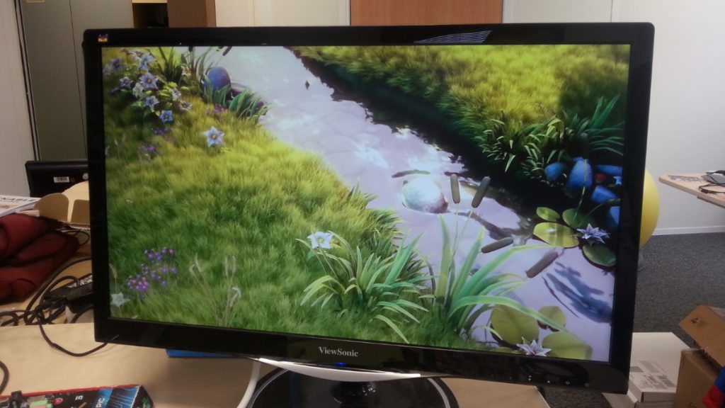
Another excerpt of the Big Buck Bunny video, in 1080p
Test coverage was also improved this week, with significantly more MPEG2 videos tested (including a standard DVD) in different resolutions up to 1080p. Some feedback from the community was also received and a first issue report will need to be investigated. Regarding platform support, initial testing of the A13 was undertaken. Although the VPU driver works apparently just as well on the A13 as already-tested platforms, the DRM driver adaptation (on the display side) for untiling VPU output buffers appears to be broken and will need to be further investigated.
In other news, a new version of the media request API has been submitted without the RFC tag (after 12 previous iterations). While we’ve been testing this new version along the course of its development, we are also taking the occasion to rebase our Sunxi-Cedrus VPU driver on top of this new version and take the received feedback into account.
Maxime continued the work on H264, and almost finished a first draft for the kernel driver side. Most of the code should be there now, the next steps are going to be making sure that no parts are missing and starting to test with cedrus-frame-test!
This week started off with numerous reviews received on the patchset introducing the Sunxi-Cedrus VPU driver. Lots of constructive comments, questions and improvements were discussed, which will help improve the driver for the next iteration of the series. Changes to other drivers will also have to be implemented, in particular to the SRAM controller found on Allwinner platforms, which needs to handle access to the SRAM by the VPU.
Maxime worked on refactoring needed to ease the support for the H264, rebasing on the latest version submitted upstream and making sure that everything still works fine. He eventually pushed them in our 4.17 branch on github, and will now focus on landing H264 support itself.
The work carried out by Paul this week was focused on the libva-cedrus VAAPI backend, which supports the Sunxi-Cedrus kernel driver on the userspace side. The backend is used by VLC (when it is configured to use VAAPI for video decoding) to play MPEG2 videos such as the ones available from the Linaro sample media. libva-cedrus was significantly improved over the week, with around 80 commits featuring a major cleanup of the code that includes, along with other changes:
coding style harmonization
proper error checking and reporting instead of assertions
the removal of the unsupported MPEG4 code
the introduction of dedicated v4l2 helpers based on those developed for cedrus-frame-test
the reorganization of v4l2 source and destination buffers management, where both are now tied to a specific surface and kept in sync
the update of the definitions to match the latest patchset
the implementation of the final rendering at picture end time
This work significantly improved the compatibility with VLC, which was previously dropping several frames. With these changes, VLC is now properly showing the decoded videos playing close to 25 fps when there is no software scaling involved. The performance is not as good with VLC as it is with cedrus-frame-test, which uses a dedicated DRM plane directly while VLC and libva-cedrus use the software untiling code and buffer copies to display each frame.
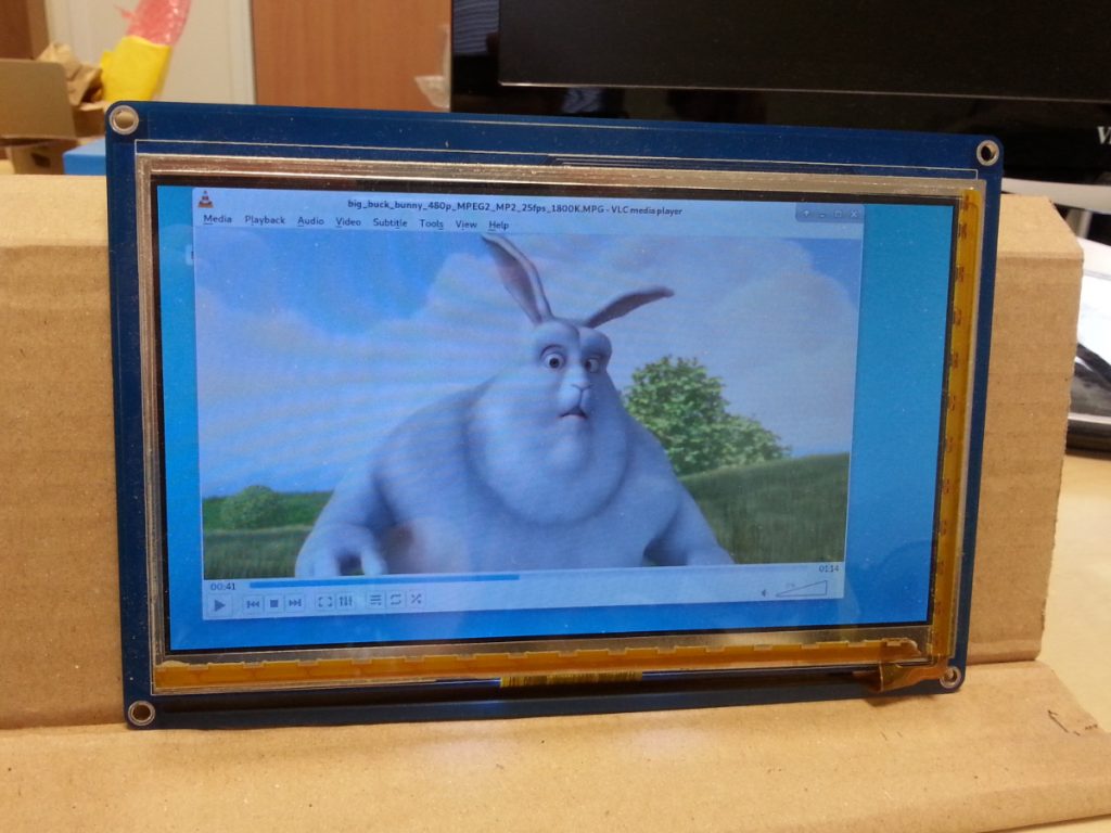
VLC playing the Big Buck Bunny video with libva-cedrus
Some attention was also given to GStreamer over the week. Although compatibility with our VAAPI backend and display pipeline is not there yet, the VAAPI backend rewrite allowed moving forward and GStreamer now displays the first decoded frame. While the operations for decoding the frames are correctly scheduled, they are only requested to be displayed sporadically, with no effect on the screen. This issue will need to be further investigated before a basic decoding pipeline can be used with GStreamer, with a video output either to a regular X window or to a DRM plane directly. MPV was also tested out this week, without much success in coordinating the rendering and display parts involved with the VAAPI pipeline. Thus, MPV support will also require more investigation before it can be properly supported.
While we initially decided to focus on GStreamer for implementing DMABUF buffer sharing between the VPU and the display engine, cedrus-frame-test (the standalone userspace implementation supporting the Sunxi-Cedrus VPU driver) allows us to directly work on implementing DMABUF support. So even though GStreamer does not work with libva-cedrus at this point, DMABUF support was started in a dedicated branch of the cedrus-frame-test repository. DMABUF is currently failing on the kernel side, when validating the page number of the requested DMA buffer. In this area as well, further investigation and work will be needed.
In the meantime, the Sunxi-Cedrus page on the linux-sunxi wiki was updated with the latest status of Sunxi-Cedrus support, instructions to build and install libva-cedrus and cedrus-frame-test as well as configure VLC for decoding MPEG2 videos. Feedback and test reports are welcome, especially regarding videos that are not decoded properly and show visual artifacts. The community around Sunxi-Cedrus hangs out on the #linux-sunxi and #cedrus channels of the freenode IRC network, so it is the best place to ask questions and discuss all things related to Sunxi-Cedrus!
As announced last week, the second revision of the Sunxi-Cedrus driver patchset was submitted for review earlier this week. While this new revision is based on the latest version of the request API, it also includes several fixes for corner-cases of this new API, especially to use it in the context of a M2M driver. Regarding the driver itself, significant reworks were carried out (including both functional and cosmetic changes) and the driver is now more stable. It was tested on the A33 and A20 so far and works nicely on both.
The standalone tool that was developed for testing the driver, called cedrus-frame-test, has seen various improvements that allow reliably testing the Sunxi-Cedrus driver. The tool is now in a state where it can be used nicely from the command line and includes the first few frames of our reference Big Buck Bunny MPEG2 video. It also implements timestamping to have a clear idea of how long frame decoding and frame display take. A target number of frames per seconds can also be set, with error messages printed when the target fps could not be met. Finally, a dummy libVA backend was written to easily dump slices and frame metadata from videos: libva-dump.
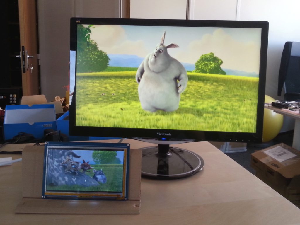
cedrus-frame-test displaying Big Buck Bunny frames decoded with Sunxi-Cedrus
Instructions to setup the kernel driver as well as cedrus-frame-test from our trees will be made available on the linux-sunxi wiki page dedicated to Sunxi-Cedrus very soon.
At this point, the time spent decoding each video frame is rather satisfying (around 5 ms as a ballpark figure) for our 854×480 demo video. We are still doing a hard copy of each frame to feed it to the display driver: that’s where the current bottleneck is. There is work left to be done in that area, first by implementing DMAbuf and also by using proper page flipping in cedrus-frame-test. We are also hitting a display issue with 4.16 on the A20, although that problem might have been fixed in 4.17 already.
Next week will be focused on (finally) adding DMAbuf support and getting libVA in shape to work with the new Sunxi-Cedrus kernel driver under VLC and GStreamer. The final patch of the first GStreamer adaptation series submitted some weeks ago was recently merged in GStreamer.
This week, Paul worked on preparing a new version of the patch series introducing support for the Sunxi-Cedrus VPU kernel driver, based upon the latest version of the Request API as submitted for review by Hans Verkuil on Monday. In order to make it easier to test the kernel driver, a standalone tool was written to decode a single frame (that was dumped beforehand). Support for displaying the decoded frame directly into a DRM plane was also added later this week, providing direct visual feedback. Finally, significant work was put into our libVA backend, that saw a significant rewrite of the memory-management logic related to video buffers.
We plan to prepare and release this new standalone tool as well as the libVA improvements when the kernel driver patch series is ready for submission, sometime next week. Specific instructions to get this up and running will also be made available on the Sunxi-Cedrus page of the linux-sunxi wiki, for one of the supported platforms. So far, we have tested the series on A33 and A20, but it is very likely that A10 and A13 will work just as well.
On his side, Maxime continued his effort on the H264 decoding. He first looked at the Chrome OS kernel and userspace code to drive the Rockchip SoCs VPU. This code is of interest because it’s basically the only stack so far that is functional, used and based on the Request API since Google is especially involved in the development of that API. He then went on with mapping the request API controls for H264 to the code for H264 decoding in the libvdpau-sunxi code that already provides an implementation for the Allwinner VPU. He then started to write some kernel code to add support for the kernel part of the API.
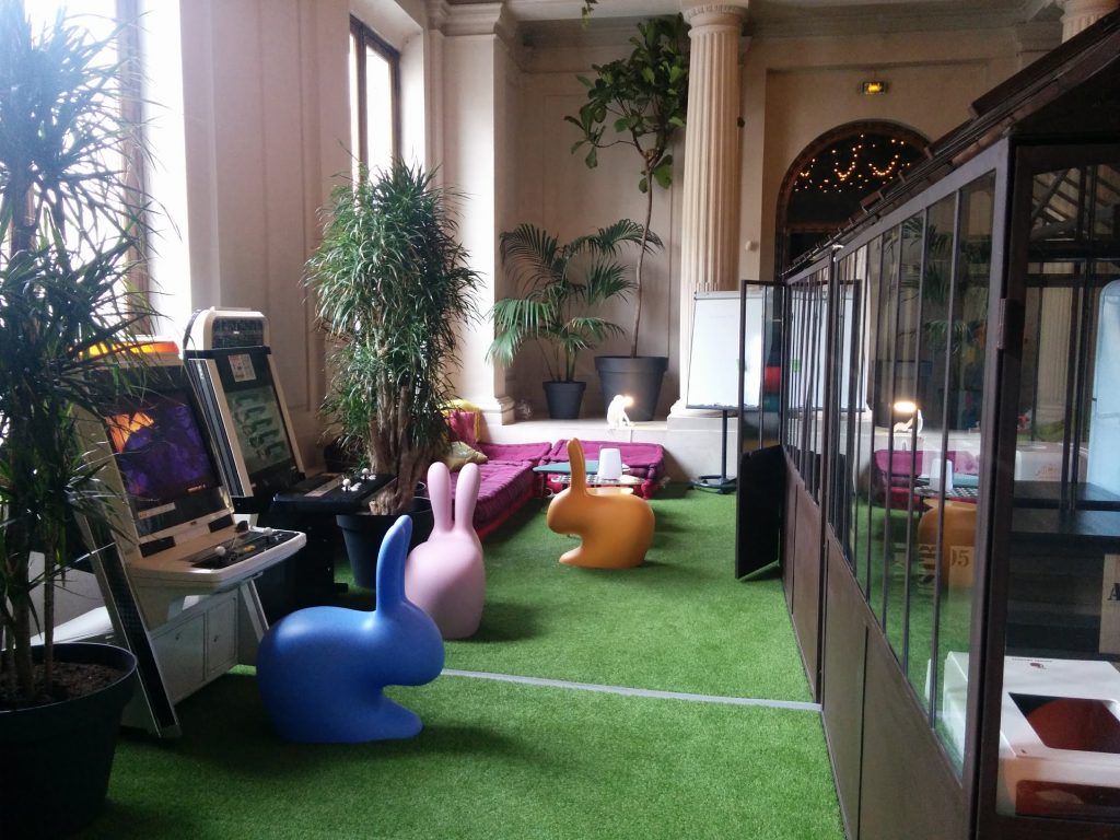
During a 3-day week-end, between March 31 and April 2, the Buildroot project organized a hackathon in Paris with six core/active developers of the project. The goal of this meeting was to make progress on outstanding patch series and reduce the backlog of contributions waiting in the project patchwork. Thomas Petazzoni, CTO and embedded Linux engineer at Bootlin participated to the event, joining Arnout Vandecappelle, Peter Korsgaard, Yann E. Morin, Romain Naour and Maxime Hadjinlian in the fantastic location provided by Scaleway.
Buildroot developers in the Jungle Room
Thomas summarized the progress day by day in three separate e-mails sent on the mailing list:
Merge of a patch series from Yann E. Morin that reworks how filesystem images are generated, to make this process compatible with top-level parallel build.
Merge of a patch series from Maxime Hadjinlian (with significant contributions from Yann E. Morin) that implements caching of Git downloads, significantly reducing the time needed to clone different versions of the same project through Git, especially big projects like the Linux kernel. An extensive summary of the changes was posted by Thomas on the mailing list.
Merge of a golang-package infrastructure, contributed by Angelo Compagnucci, to help building packages written in Go, and using the standardized Go build system.
The check-package tool was extended to validate the coding style of files outside the package/ folder, thanks to a contribution from Ricardo Martincoski.
Arnout worked on a significant number of pending Qt5 patches, and specifically merged the bump to Qt 5.10.
The LLVM patch series from Valentin Korenblit was reviewed, and thanks to this work, the initial LLVM package was merged a few days after the hackathon.
Last but not least, a large number of patches sitting in patchwork have been discussed, and either applied (after some rework) or reviewed (with comments made on the mailing list).
Working at Scaleway
In total, 222 commits have been pushed to the master branch during this meeting, and the backlog of patches has reduced from ~350 patches to ~175 patches.
Once again, the Buildroot community would like to thank Scaleway for hosting this event! The next Buildroot meeting will most likely take place right before the Embedded Linux Conference in Edinburgh, on October 20-21.
This week has seen progress on the GStreamer front: the segmentation fault that was a blocker when interfacing our libva backend with gstreamer-vaapi was investigated and understood. An associated bug was reported to the GNOME bug tracker, with all the gory details attached. Since the issue was in fact due to the assembly routine imported from libvdpau-sunxi smashing the malloc heap metadata, the bug report was closed. Using valgrind proved very useful for diagnosing the issue. Since we are not going to keep using the software-based untiling method through this assembly code, no time was spent on investigating and fixing the issue there.
The integration of changes in GStreamer for our case is also moving forward, with the submission of newer iterations of the related patches when requested. There are still issues left to fix with GStreamer, although things are looking better and better. Plenty of small bugs and mistakes have been identified and resolved in both our kernel driver and VAAPI backend in the process.
A new version of the request API has also been submitted for review and comments by Hans Verkuil. We have started rebasing our VPU driver on top of this new version and hope to send out this new version sometime next week.
We also started to look into H264, mostly by setting up a good test scenario for H264 (using the libvdpau-sunxi and an Allwinner kernel), making sure that it can actually decode H264 videos (which it does), and building similar setup with the mainline kernel and our libva implementation.
Stay tuned for more development updates related to Allwinner VPU support in mainline Linux!
Drawing from Mylène Josserand, based on a picture from Samuel Blanc under CC-BY-SA 4.16 out for a week now, it shouldn’t come as a surprise that it’s time for our traditional article summing up our most recent contributions to the latest version of the Linux kernel.
According to LWN statistics, Bootlin stands at the 13th place in the company ranking in terms of number of lines changed and we even have one of our engineers, Miquèl Raynal, appearing in the top 20 contributors with regards to number of lines changed thanks to his complete rework of the Marvell NAND controller driver and his addition of the exec_op() API to the NAND framework.
The main highlights of our contributions are:
For Marvell platforms,
Antoine Ténart improved the inside-secure crypto accelerator driver to support the EIP97 variant of the hardware block, which is used on the Marvell Armada 3700. This driver was already supporting the EIP197 variant, used on Marvell Armada 7K/8K. This new EIP97 support allows to enable the use of the crypto accelerator on the popular EspressoBin platform, a $49 board based on the Marvell Armada 3700,
Antoine Ténart also contributed a number of fixes to the inside-secure crypto accelerator driver,
Antoine Ténart also contributed a few fixes to the mvpp2 network driver, used for the Ethernet controller on the Marvell Armada 7K/8K.
Both Boris Brezillon and Miquèl Raynal contributed numerous fixes,
Miquèl Raynal contributed the exec_op API to simplify how NAND controllers interact with the core with regards to sending NAND operations. For more details about Miquèl’s work, see the video and slides of his talk at the latest ELC,
For Microsemi Ocelot platforms:
Alexandre Belloni added support for Microsemi Ocelot SoC’s pinctrl. This is the very first piece of the support for the Microsemi VSC7513/7514 MIPS processors, with the rest of the basic platform support expected to appear in 4.17,
Maxime Ripard added support for LVDS for the A83T in the DRM subsystem and contributed a few fixes along the way,
Mylène Josserand added ADC support for the audio codec present on the sun8i family,
Alexandre Belloni fixed a few race conditions in the AC100 RTC driver,
Maxime Ripard also contributed a fix for gpiolib failing to defer its probing until a GPIO controller is registered,
Bootlin engineers are not only contributors, but also maintainers of various subsystems in the Linux kernel, which means they are involved in the process of reviewing, discussing and merging patches contributed to those subsystems:
Maxime Ripard, as the Allwinner platform co-maintainer, merged 66 patches from other contributors
Boris Brezillon, as the MTD/NAND maintainer, merged 73 patches from other contributors
Alexandre Belloni, as the RTC maintainer and Atmel platform co-maintainer, merged 23 patches from other contributors
Grégory Clement, as the Marvell EBU co-maintainer, merged 16 patches from other contributors
Here is the commit by commit detail of our contributions to 4.16:
As discussed in our previous blog post, Bootlin had again a strong presence at the Embedded Linux Conference North-America, with 8 attendees, 5 talks, one BoF and two E-ALE tutorial sessions.
In this blog post, we would like to highlight a number of talks from the conference that we found interesting. Each Bootlin engineer who attended the conference has selected one talk, and gives his/her feedback about this talk.
Device Tree BoF – Frank Rowand
Talk selected by Michael Opdenacker
The Device Tree BoF (Birds of a Feather session, which means an informal session about a technical topic, allowing participants to openly share questions and information) has been part of Embedded Linux Conferences for at least 2 or 3 years. For me, it has always been a good source of updates about the topic.
Frank started by sharing details about the Device Tree Workshop held in October in Prague, a one day meet-up and workshop for Device Tree contributors (like Maxime Ripard and Thomas Petazzoni from Bootlin who were invited), to address issues and plan for the next months. Slides and notes can be found on elinux.org.
Frank then went on by mentioning utilities, such as:
scripts/dtc/dt_to_config. It is not very new in the mainline kernel, but useful to generate a kernel configuration suitable for the devices present on your platform, in case you didn’t know this tool exists.
There’s an upcoming patch adding options to dtc (--annotate --full) to keep track of the line numbers in the device tree sources. This helps to locate in which DT source file a given property value comes from. The patch was idle for some time but Julia Lawall volunteered to take care of it. Thanks to her updates, this feature should be accepted in mainline soon.
The device tree compiler in mainline has also been augmented with further build checks. You can now use them by adding W=1 to make dtb. Here is an example for the Beagle Bone Black dtb:
make W=1 am335x-boneblack.dtb
  CHK     scripts/mod/devicetable-offsets.h
  DTC     arch/arm/boot/dts/am335x-boneblack.dtb
arch/arm/boot/dts/am335x-boneblack.dtb: Warning (unit_address_vs_reg): Node /ocp/i2c@44e0b000/tda19988 has a reg or ranges property, but no unit name
arch/arm/boot/dts/am335x-boneblack.dtb: Warning (unit_address_vs_reg): Node /ocp/i2c@44e0b000/tda19988/ports/port@0 has a unit name, but no reg property
arch/arm/boot/dts/am335x-boneblack.dtb: Warning (unit_address_vs_reg): Node /ocp/i2c@44e0b000/tda19988/ports/port@0/endpoint@0 has a unit name, but no reg property
arch/arm/boot/dts/am335x-boneblack.dtb: Warning (unit_address_vs_reg): Node /ocp/ethernet@4a100000/slave@4a100200 has a unit name, but no reg property
arch/arm/boot/dts/am335x-boneblack.dtb: Warning (unit_address_vs_reg): Node /ocp/ethernet@4a100000/slave@4a100300 has a unit name, but no reg property
arch/arm/boot/dts/am335x-boneblack.dtb: Warning (unit_address_vs_reg): Node /ocp/lcdc@4830e000/port/endpoint@0 has a unit name, but no reg property
arch/arm/boot/dts/am335x-boneblack.dtb: Warning (simple_bus_reg): Node /ocp/l4_wkup@44c00000/prcm@200000/clocks missing or empty reg/ranges property
arch/arm/boot/dts/am335x-boneblack.dtb: Warning (simple_bus_reg): Node /ocp/l4_wkup@44c00000/prcm@200000/clockdomains missing or empty reg/ranges property
arch/arm/boot/dts/am335x-boneblack.dtb: Warning (simple_bus_reg): Node /ocp/l4_wkup@44c00000/scm@210000/scm_conf@0/clocks missing or empty reg/ranges property
arch/arm/boot/dts/am335x-boneblack.dtb: Warning (simple_bus_reg): Node /ocp/l4_wkup@44c00000/scm@210000/clockdomains missing or empty reg/ranges property
As far as I am concerned, the most interesting news remained the one that since Linux 4.15, device tree overlays are now easier to code. You no longer have to define weird “fragment” elements. You can now directly write normal nodes and use labels. The syntax is now exactly the same as for regular device tree sources!
For more details, grab the slides and if you event want to follow the discussions that happened that day, watch the video.
Tutorial: Introduction to Reverse Engineering – Mike Anderson
Talk selected by Quentin Schulz
Mike presented in an unusual 2-hour-long slot the different techniques to reverse-engineer things and the different reasons why you’d do so. After a mandatory disclaimer that reverse engineering may be illegal in some regions of the world, he introduced the different tools that anyone aspiring to reverse engineer should possess: from the obvious logic analyzer, multimeter, screwdrivers to the surprising heat gun. He then gave the first and very important step of the reverse engineering process: gathering information about the product by looking for patents, the FCC registration, manufacturer as well as carefully opening its case to examine the different components (maybe with the help of a microscope).
Later, Mike gave the multiple ways to retrieve the firmwares from the product, from the soldering of a JTAG interface to the downloading from the official website. He then offered some tools that can be used to dive into binaries and start the guessing game, and he finished his talk with an example of a reverse engineering of a protocol which required a lot of guessing and social reverse engineering.
Mike’s talk was pleasant to attend because of the high-level presentation of how to do reverse engineering while giving a quick real-life example.
For more details, watch the video and grab the slides.
Graphics Performance Analysis with FrameRetrace: A Responsive UI for ApiTrace – Mark Janes, Intel
Talk selected by Boris Brezillon
I first heard of FrameRetrace when Eric Anholt asked us to add support for the VC4 GPU to this tool, and my experience with it had been rather frustrating in that I was mainly struggling to make it work on a not yet supported architecture instead of being a simple user. So, when I saw that Mark was giving a talk on FrameRetrace usefulness and how to use it, I figured I couldn’t miss it. Well, those who looked carefuly at the schedule know I couldn’t attend it because I was giving my talk at the same time, but I did see it at FOSDEM a month before, and I’m pretty sure not much has changed since then.
Mark first described the GPU debugging/perf-anlysis tools ecosystem, saying that each GPU vendor has its own proprietary tools which most of the time are only supported on Windows. FrameRetrace is an attempt at providing a tool that exposes similar features while being open-source, cross-platform, and easily extensible to new hardware. This project is actually based on an exisiting project called ApiTrace, which it uses to capture OpenGL traces. The new feature that is interesting in FrameRetrace is that you can select the frame you want to replay, get all the hardware perf counters exposed by the GPU for this specific rendering job in order to figure out what is going wrong and then play with the OpenGL code to see how you can make things better and replay the rendering job with your local modification to see if it actually solves the problem.
I must admit I was really impressed by the demo, and now I understand why Eric (and others in the community) would like to have their GPU properly supported in FrameRetrace. It really looks like the kind of tool you don’t know you need until you’ve tested it, but once you do, you can’t do without it.
For more details, watch the video and grab the slides.
The Salmon Diet: Up-Streaming Drivers as a Form of Optimization – Gilad Ben-Yossef
Talk selected by Miquèl Raynal
Gilad was hired about a year ago to become the maintainer of the ARM® TrustZone® CryptoCell® device driver. Until now this driver was out of tree until it has been decided to upstream it. Here starts Gilad’s story.
It appeared that the right way to make it upstream was to go through the staging tree and the whole process around it. It was the first time for him to do it that way, that is why he felt it was interesting to share his experience.
At the beginning of his talk, he recalls that the driver was actually working, people already relied on it. Plus, it was released under the GPL. While all of this could make you think it was clean enough, Gilad realized that people who wrote it actually did not think about upstreaming and almost every patch to clean that driver removed more lines than it added, shrinking step by step the driver until 30% of the lines were removed!
Of course, removing the existing hardware abstraction macros was something to do, as well as running and correcting the whole checkpatch.pl output, but there are plenty of other good habits that one can adapt to his own situation, explained and well illustrated all along this talk.
For more details, watch the video and grab the slides.
Measuring and Summarizing Latencies using the Trace Event Subsystem – Tom Zanussi
Talk selected by Maxime Chevallier
Having some experience dealing with RT topics on Linux, I was looking forward to seeing Tom’s talk about these tracing features.
He gave really good examples on how to use the existing ‘latency histogram’ traces to get a cyclictest-like metric of wakeup latencies by measuring the time between sched_waking and sched_switch, and explaining how this could be re-used for other measurements such as network latencies.
What he presented was more than just having a trace in a buffer when a function is called. The tracing subsystem allows the use of handlers to perform actions when an event occurs. As an example, he demonstrated how to use the onmax handler to accumulate the maximum wakeup latency observed, each time saving crucial pieces of information on the execution context.
He then went on to describe the next-level features that are being merged, namely function events by Steven Rostedt, and Inter events by Tom himself. They allow the user to use any of the kernel functions as tracepoints, and build complex events and traces to pinpoint really specific sequences.
I recommend to read this LWN article on inter-event tracing, and of course have a look at Tom’s talk and slides.
Steering Xenomai into the Real-Time Linux Future – Jan Kiszka
Talk selected by Thomas Petazzoni
In this talk, long-term Xenomai developer and Siemens engineer Jan Kiszka gave a very interesting status of the Xenomai project and its roadmap. He started by refreshing the audience about what Xenomai is: an RTOS-to-Linux portability framework. It comes in two flavors: a co-kernel extension for a patched Linux kernel, and as libraries running for native Linux (including PREEMPT_RT). He then went on to compare the respective advantages and drawbacks of the two flavors, citing accurate modeling of legacy RTOS behavior and strong separation of real-time vs. non real-time code as the key advantages of the co-kernel approach.
Jan then summarized the history of Xenomai, from the early days as a sub-project of RTAI to the current status of Xenomai 3.0, released in 2015 after more than 5 years of development. However, even though Xenomai is widely used in the industry, its development relies on just a few individuals. Siemens is a heavy user of Xenomai, and in 2017, they started a discussion: should they migrate away from Xenomai or invest into it. Siemens made the decision to invest in the project. The same year, Xenomai main developer Philippe Gerum published an e-mail RTnet, Analogy and the elephant in the room also calling for help to maintain some parts of Xenomai.
Following those discussions, some changes were decided in the Xenomai project: Philippe Gerum will step back from the project lead, and Jan Kiszka will take over his role.
Regarding the I-Pipe kernel patch (which allows to support the co-kernel approach), the Xenomai project will discontinue a number of architectures (nios2, SH, Blackfin, PPC64, ARM < v7) and will only maintain patches for the latest Linux kernel LTS, in order to reduce the maintenance effort.
Jan announced that Xenomai 3.0.7 is soon to be released, that Xenomai 3.1 will introduce ARM64 support, and that Xenomai 2 is unmaintained and therefore users should migrate to Xenomai 3. He also gave a status on the driver stacks, citing that RTnet needs more love, and that Analogy is orphaned and needs a new maintainer.
Towards the end of his talk, Jan then started discussing the more distant future of Xenomai. The future version of Xenomai has the goal of improving the integration of the co-kernel approach, to simplify maintenance and possibly provide a chance to be upstreamed in Linux. This new approach will be split in two elements, called Dovetail (interrupt routing, co-kernel hooks) and Steely (co-kernel implementation). He made it clear that this is currently not production-ready at all. He noted that this new implementation allows a significant reduction of the code base, about 50% smaller than the current implementation. The code is already available in two Git repositories: Dovetail and Steely.
All in all, Jan’s talk was a very interesting one, providing a good coverage of Xenomai’s status and future. The video of his talk is definitely worth watching, and the slides are also available.
An Introduction to Asymmetric Multiprocessing: When this Architecture can be a Game Changer and How to Survive It – Nicola La Gloria & Laura Nao
Talk selected by Mylène Josserand
In this talk, Nicola La Gloria and Laura Nao from Kynetics presented how to handle communication between a micro-controller running bare metal code and a CPU with a full OS (such as GNU/Linux or Android).
They showed the different approaches for communication (supervised or not supervised: i.e. CPU and MCU can communicate using an hypervisor or directly) and presented the Inter-Processing Communication.
After this introduction, Laura told us about their use-case, running on an NXP i.MX7, which comprises a Cortex-M4 micro-controller and a Cortex-A7 processor: the MCU retrieves data from a sensor, which will be displayed by the CPU.
She gave feedback on how they implemented this communication and the different mechanisms used (Message Unit, RPMsg, RDC, kexec/kdump, etc). The explanation of the different mechanisms was really interesting, and particularly relevant for those who had never heard about them.
They did a short tutorial and gave some tips that would definitely be appreciated by people who start this kind of project. And finally, they did a demonstration of all the work they have done.
So if you are interested in the subject or even only for your general knowledge, have a look at their talk (video and slides).
System-in-Package Technology: Making it Easier to Build Your Own Linux Computer – Erik Welsh & Jason Kridner
Talk selected by Alexandre Belloni
Eric Welsh started to talk about how software influences hardware design and why open source hardware matters. He then presented the System-in-Package technology and in particular the Octavo OSD3358. It includes a TI AAM335x SoC, DDR3 SDRAM, a PMIC and all the related power circuitry, components which are always required. This allows the hardware engineers to concentrate on the added value of the final product.
Great pictures and videos of the SiP internals and its manufacturing process were shown.
Jason then came on stage to present the OSD3358 integration on the PocketBeagle.
Eric finally explained how easy it is to assemble the OSD3358 on a PCB, even by hand with a video to prove it. He finally concluded by summing up the benefits of using a SiP: easy bring-up, lower cost of PCB, easy manufacturing and migration from SBC prototyping to custom PCB.
It was quite enlightening for software engineers as it showed the hardware internals with some great details.
Have a look at the video and slides.
In conclusion, this was again a really nice opportunity to share and acquire knowledge from other engineers deeply involved in the Open Source community, as well as meeting people that we sometimes know only by their name on a mailing list. Next year this event will happen in Monterey Bay, California (March 19 – 21, 2019). See you there!
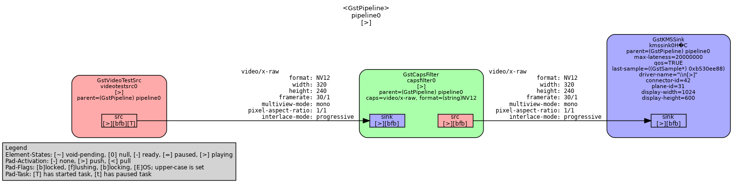
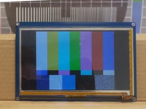
While this week’s goal was set to supporting dmabuf in our Sunxi-Cedrus VAAPI implementation with GStreamer, progress was made on GStreamer support alone. The first milestone was displaying the video from videotestsrc, which produces a sample test output, to kmssink, which handles video output directly with DRM planes.
The Gstreamer pipeline for the testThe working result on display
On the VAAPI side, things are more complicated and a number of different areas of the sunxi-cedrus VAAPI backend had to be reworked. For instance, the slices constituting MPEG2 frames are not submitted in the same way by VLC and GStreamer. Buffers management is also done slightly differently between these two users of libVA. The net result is that a segmentation fault caused by a memory management mishaps is occurring with GStreamer and is still being investigated.
This week was also the occasion to dig into the partial reference code that Allwinner published in 2015 (to grasp a better understanding of the MPEG2 decoding process with the VPU) and start updating the register documentation on the linux-sunxi wiki, where some fields documented by the reference code were still marked as unknown. The Sunxi-Cedrus page was also updated to reflect the current status and effort. These resources will get updated as development happens. More precisely, we’d like to provide instructions to deploy this work, once it has reached a decent level of usability. Stay tuned for our next update!