Beyond boot testing: custom tests with LAVA

Since April 2016, we have our own automated testing infrastructure to validate the Linux kernel on a large number of hardware platforms. We use this infrastructure to contribute to the KernelCI project, which tests every day the Linux kernel. However, the tests being done by KernelCI are really basic: it’s mostly booting a basic Linux system and checking that it reaches a shell prompt.

However, LAVA, the software component at the core of this testing infrastructure, can do a lot more than just basic tests.

The need for custom tests

With some of our engineers being Linux maintainers and given all the platforms we need to maintain for our customers, being able to automatically test specific features beyond a simple boot test was a very interesting goal.

In addition, manually testing a kernel change on a large number of hardware platforms can be really tedious. Being able to quickly send test jobs that will use an image you built on your machine can be a great advantage when you have some new code in development that affects more than one board.

We identified two main use cases for custom tests:

  • Automatic tests to detect regression, as does KernelCI, but with more advanced tests, including platform specific tests.
  • Manual tests executed by engineers to validate that the changes they are developing do not break existing features, on all platforms.

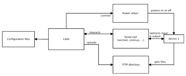
Overall architecture

Several tools are needed to run custom tests:

  • The LAVA instance, which controls the hardware platforms to be tested. See our previous blog posts on our testing hardware infrastructrure and software architecture
  • An appropriate root filesystem, that contains the various userspace programs needed to execute the tests (benchmarking tools, validation tools, etc.)
  • A test suite, which contains various scripts executing the tests
  • A custom test tool that glues together the different components

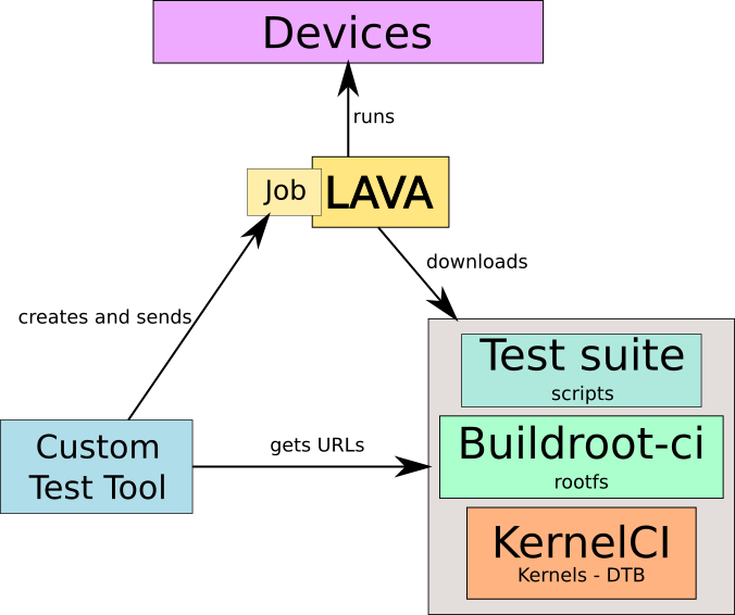
The custom test tool knows all the hardware platforms available and which tests and kernel configurations apply to which hardware platforms. It identifies the appropriate kernel image, Device Tree, root filesystem image and test suite and submits a job to LAVA for execution. LAVA will download the necessary artifacts and run the job on the appropriate device.

Building custom rootfs

When it comes to test specific drivers, dedicated testing, validation or benchmarking tools are sometimes needed. For example, for storage device testing, bonnie++ can be used, while iperf is nice for networking testing. As the default root filesystem used by KernelCI is really minimalist, we need to build our owns, one for each architecture we want to test.

Buildroot is a simple yet efficient tool to generate root filesystems, it is also used by KernelCI to build their minimalist root filesystems. We chose to use it and made custom configuration files to match our needs.

We ended up with custom rootfs built for ARMv4, ARMv5, ARMv7, and ARMv8, that embed for now Bonnie++, iperf, ping (not the Busybox implementation) and other tiny tools that aren’t included in the default Buildroot configuration.

Our Buildroot fork that includes our custom configurations is available as the buildroot-ci Github project (branch ci).

The custom test tool

The custom test tool is the tool that binds the different elements of the overall architecture together.

One of the main features of the tool is to send jobs. Jobs are text files used by LAVA to know what to do with which device. As they are described in LAVA as YAML files (in the version 2 of the API), it is easy to use templates to generate them based on a single model. Some information is quite static such as the device tree name for a given board or the rootfs version to use, but other details change for every job such as the kernel to use or which test to run.

We made a tool able to get the latest kernel images from KernelCI to quickly send jobs without having a to compile a custom kernel image. If the need is to test a custom image that is built locally, the tool is also able to send files to the LAVA server through SSH, to provide a custom kernel image.

The entry point of the tool is ctt.py, which allows to create new jobs, providing a lot of options to define the various aspects of the job (kernel, Device Tree, root filesystem, test, etc.).

This tool is written in Python, and lives in the custom_tests_tool Github project.

The test suite

The test suite is a set of shell scripts that perform tests returning 0 or 1 depending on the result. This test suite is included inside the root filesystem by LAVA as part of a preparation step for each job.

We currently have a small set of tests:

  • boot test, which simply returns 0. Such a test will be successful as soon as the boot succeeds.
  • mmc test, to test MMC storage devices
  • sata test, to test SATA storage devices
  • crypto test, to do some minimal testing of cryptographic engines
  • usb test, to test USB functionality using mass storage devices
  • simple network test, that just validates network connectivity using ping

All those tests only require the target hardware platform itself. However, for more elaborate network tests, we needed to get two devices to interact with each other: the target hardware platform and a reference PC platform. For this, we use the LAVA MultiNode API. It allows to have a test that spans multiple devices, which we use to perform multiple iperf sessions to benchmark the bandwidth. This test has therefore one part running on the target device (network-board) and one part running on the reference PC platform (network-laptop).

Our current test suite is available as the test_suite Github project. It is obviously limited to just a few tests for now, we hope to extend the tests in the near future.

First use case: daily tests

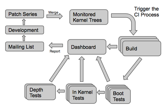
As previously stated, it’s important for us to know about regressions introduced in the upstream kernel. Therefore, we have set up a simple daily cron job that:

  • Sends custom jobs to all boards to validate the latest mainline Linux kernel and latest linux-nextli>
  • Aggregates results from the past 24 hours and sends emails to subscribed addresses
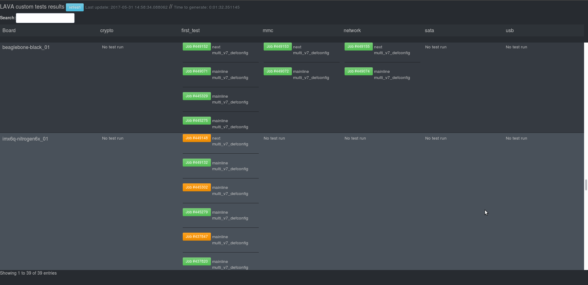
  • Updates a dashboard that displays results in a very simple page
A nice dashboard showing the tests of the Beaglebone Black and the Nitrogen6x.

Second use case: manual tests

The custom test tool ctt.py has a simple command line interface. It’s easy for someone to set it up and send custom jobs. For example:

ctt.py -b beaglebone-black -m network

will start the network test on the BeagleBone Black, using the latest mainline Linux kernel built by KernelCI. On the other hand:

ctt.py -b armada-7040-db armada-8040-db -t mmc --kernel arch/arm64/boot/Image --dtb-folder arch/arm64/boot/dts/

will run the mmc test on the Marvell Armada 7040 and Armada 8040 development boards, using the locally built kernel image and Device Tree.

The result of the job is sent over e-mail when the test has completed.

Conclusion

Thanks to this custom test tool, we now have an infrastructure that leverages our existing lab and LAVA instance to execute more advanced tests. Our goal is now to increase the coverage, by adding more tests, and run them on more devices. Of course, we welcome feedback and contributions!

Software architecture of Bootlin’s lab

As stated in a previous blog post, we officially launched our lab on 2016, April 25th and it is contributing to KernelCI since then. In a series of blog post, we’d like to present in details how our lab is working.

We previously introduced the lab and its integration in KernelCI, and presented its hardware infrastructure. Now is time to explain how it actually works on the software side.

Continuous integration in Linux kernel

Because of Linux’s well-known ability to run on numerous platforms and the obvious impossibility for developers to test changes on all these platforms, continuous integration has a big role to play in Linux kernel development and maintenance.

More generally, continuous integration is made up of three different steps:

  • building the software which in our case is the Linux kernel,
  • testing the software,
  • reporting the tests results;
KernelCI complete process

KernelCI checks hourly if one of the Git repositories it tracks have been updated. If it’s the case then it builds, from the last commit, the kernel for ARM, ARM64 and x86 platforms in many configurations. Then it stores all these builds in a publicly available storage.

Once the kernel images have been built, KernelCI itself is not in charge of testing it on hardware. Instead, it delegates this work to various labs, maintained by individuals or organizations. In the following section, we will discuss the software architecture needed to create such a lab, and receive testing requests from KernelCI.

Core software component: LAVA

At this moment, LAVA is the only supported software by KernelCI but note that KernelCI offers an API, so if LAVA does not meet your needs, go ahead and make your own!

What is LAVA?

LAVA is a self-hosted software, organized in a server-dispatcher model, for controlling boards, to automate boot, bootloader and user-space testing. The server receives jobs specifying what to test, how and on which boards to run those tests, and transmits those jobs to the dispatcher linked to the specified board. The dispatcher applies all modifications on the kernel image needed to make it boot on the said board and then fully interacts with it through the serial.

Since LAVA has to fully and autonomously control boards, it needs to:

  • interact with the board through serial connection,
  • control the power supply to reset the board in case of a frozen kernel,
  • know the commands needed to boot the kernel from the bootloader,
  • serve files (kernel, DTB, rootfs) to the board.

The first three requirements are fulfilled by LAVA thanks to per-board configuration files. The latter is done by the LAVA dispatcher in charge of the board, which downloads files specified in the job and copies them to a directory accessible by the board through TFTP.

LAVA organizes the lab in devices and device types. All identical devices are from the same device type and share the same device type configuration file. It contains the set of bootloader instructions to boot the kernel (e.g.: how and where to load files) and the bootloader configuration (e.g.: can it boot zImages or only uImages). A device configuration file stores the commands run by a dispatcher to interact with the device: how to connect to serial, how to power it on and off. LAVA interacts with devices via external tools: it has support for conmux or telnet to communicate via serial and power commands can be executed by custom scripts (pdudaemon for example).

Control power supply

Some labs use expensive Switched PDUs to control the power supply of each board but, as discussed in our previous blog post we went for several Devantech ETH008 Ethernet-controlled relay boards instead.

Linaro, the organization behind LAVA, has also developed a software for controlling power supplies of each board, called pdudaemon. We added support for most Devantech relay boards to pdudaemon.

Connect to serial

As advised in LAVA’s installation guide, we went with telnet and ser2net to connect the serial port of our boards. Ser2net basically opens a Linux device and allows to interact with it through a TCP socket on a defined port. A LAVA dispatcher will then launch a telnet client to connect to a board’s serial port. Because of the well-known fact that Linux devices name might change between reboots, we had to use udev rules in order to guarantee the serial we connect to is the one we want to connect to.

Actual testing

Now that LAVA knows how to handle devices, it has to run jobs on those devices. LAVA jobs contain which images to boot (kernel, DTB, rootfs), what kind of tests to run when in user space and where to find them. A job is strongly linked to a device type since it contains the kernel and DTB specifically built for this device type.

Those jobs are submitted to the different labs by the KernelCI project. To do so, KernelCI uses a tool called lava-ci. Amongst other things, this tool contains a big table of the supported platforms, associating the Device Tree name with the corresponding hardware platform name. This way, when a new kernel gets built by KernelCI, and produces a number of Device Tree Blobs (.dtb files), lava-ci knows what are the corresponding hardware platforms to run the kernel on. It submits the jobs to all the labs, which will then only run the tests for which they have the necessary hardware platform. We have contributed a number of patches to lava-ci, adding support for the new platforms we had in our lab.

LAVA overall architecture

Reporting test results

After KernelCI has built the kernel, sent jobs to contributing labs and LAVA has run the jobs, KernelCI will then get the tests results from the labs, aggregate them on its website and notify maintainers of errors via a mailing list.

Challenges encountered

As in any project, we stumbled on some difficulties. The biggest problems we had to take care of were board-specific problems.

Some boards like the Marvell RD-370 need a rising edge on a pin to boot, meaning we cannot avoid pressing the reset button between each boot. To work out this problem, we had to customize the hardware (swap resistors) to bypass this limitation.

Some other boards lose their serial connection. Some lose it when resetting their power but recover it after a few seconds, problem we found acceptable to solve by infinitely reconnecting to the serial. However, we still have a problem with a few boards which randomly close their serial connection without any reason. After that, we are able to connect to the serial connection again but it does not send any character. The only way to get it to work again is to physically re-plug the cable used by the serial connection. Unfortunately, we did not find yet a way to solve this bug.

The Linux kernel of our server refused to bind more than 13 USB devices when it was time to create a second drawer of boards. After some research, we found out the culprit was the xHCI driver. In modern computers, it is possible to disable xHCI support in the BIOS but this option was not present in our server’s BIOS. The solution was to rebuild and install a kernel for the server without the xHCI driver compiled. From that day, the number of USB devices is limited to 127 as in the USB specification.

Conclusion

We have now 35 boards in our lab, with some being the only ones represented in KernelCI. We encourage anyone, hobbyists or companies, to contribute to the effort of bringing continuous integration of the Linux kernel by building your own lab and adding as many boards as you can.

Interested in becoming a lab? Follow the guide!

Hardware infrastructure of Bootlin’slab

As stated in a previous blog post, we officially launched our lab on 2016, April 25th and it is contributing to KernelCI since then. In a series of blog post, we’d like to present in details how our lab is working, starting with this first blog post that details the hardware infrastructure of our lab.

Introduction

In a lab built for continuous integration, everything has to be fully automated from the serial connections to power supplies and network connections.

To gather as much information as we can get to establish the specifications of the lab, our engineers filled a spreadsheet with all boards they wanted to have in the lab and their specificities in terms of connectors used the serial port communication and power supply. We reached around 50 boards to put into our lab. Among those boards, we could distinguish two different types:

  • boards which are powered by an ATX power supply,
  • boards which are powered by different power adapters, providing either 5V or 12V.

Another design criteria was that we wanted to easily allow our engineers to take a board out of the lab or to add one. The easier the process is, the better the lab is.

Home made cabinet

Bootlin' 8 drawers lab
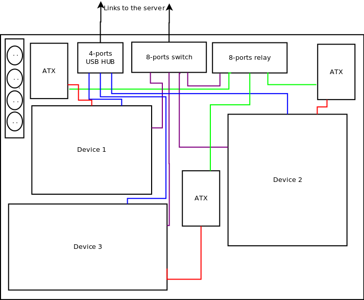
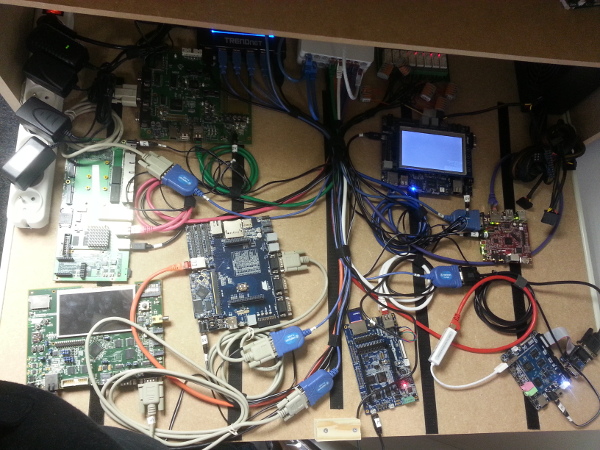
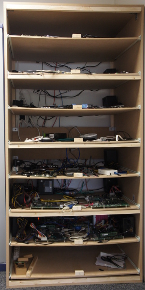
To meet the size constraints of Bootlin office, we had to make the lab fit in a 100cm wide, 75cm deep and 200cm high space. In order to achieve this, we decided to build the lab as a large home made cabinet, with a number of drawers to easily access, change or replace the boards hosted in the lab. As some of our boards provide PCIe connectors, we needed to provide enough height for each drawer, and after doing a few measurements, decided that a 25cm height for our drawers would be fine. With a total height of 200cm, this gives a maximum of 8 drawers.

In addition, it turns out that most of our boards powered by ATX power supplies are rather large in size, while the ones powered by regular power adapters are usually much smaller. In order to simplify the overall design, we decided that all large boards would be grouped together on a given set of drawers, and all small boards would be grouped together on another set of drawers: i.e we would not mix large and small boards in the same drawer. With the 100cm x 75cm size limitation, this meant a drawer for small boards could host up to 8 boards, while a drawer for large boards could host up to 4 boards. From the spreadsheet containing all the boards supposed to be in the lab, we eventually decided there would be 3 large drawers for up to 12 large boards and 5 small drawers for up to 40 small or medium-sized boards.

Furthermore, since the lab will host a server and a lot of boards and power supplies, potentially producing a lot of heat, we have to keep the lab as open as it can be while making sure it is strong enough to hold the drawers. We ended up building our own cabinet, made of wood bought from the local hardware store.

We also want the server to be part of the lab. We already have a small piece of wood to strengthen the lab between the fourth and sixth drawers we could use to fix the server. We decided to give a mini-PC (NUC-like) a try, because, after all, it’s only communicating with the serial of each board and serving files to them. Thus, everything related to the server is fixed and wired behind the lab.

Make the lab autonomous

What continuous integration for the Linux kernel typically needs are control of:

  1. the power for each board
  2. serial port connection
  3. a way to send files to test, typically the kernel image and associated files

In Bootlin lab, these different tasks are handled by a dedicated server, itself hosted in the lab.

Serial port control

Serial connections are mostly handled via USB on the server side but there are many different connectors on the target side (in our lab, we have 6 different connectors: DE9, microUSB, miniUSB, 2.54″ male pins, 2.54″ female pins and USB-B). Therefore, our server has to have a physical connection with each of the 50 boards present in the lab. The need for USB hubs is then obvious.

Since we want as few cables connecting the server and the drawers as possible, we decided to have one USB hub per drawer, be it a large drawer or a small drawer. In a small drawer, up to 8 boards can be present, meaning the hub needs at least 8 USB ports. In a large drawer, up to 4 serial connections can be needed so smaller and more common USB hubs can do the work. Since the serial connection may draw some current on the USB port, we wanted all of our USB hubs to be powered with a dedicated power supply.

All USB hubs are then connected to a main USB hub which in turn is connected to our server.

Power supply control

Our server needs to control each board’s power to be able to automatically power on or off a board. It will power on the board when it needs to test a new kernel on it and power it off at the end of the test or when the kernel has frozen or could not boot at all.

In terms of power supplies, we initially investigated using Ethernet-controlled multi-sockets (also called Switched PDU), such as this device. Unfortunately, these devices are quite expensive, and also often don’t provide the most appropriate connector to plug the cheap 5V/12V power adapters used by most boards.

So, instead, and following a suggestion from Kevin Hilman (one of KernelCI’s founder and maintainer), we decided to use regular ATX power supplies. They have the advantage of being inexpensive, and providing enough power for multiple boards and all their peripherals, potentially including hard drives or other power-hungry peripherals. ATX power supplies also have a pin, called PS_ON#, which when tied to the ground, powers up the ATX power supply. This easily allows to turn an ATX power supply on or off.

In conjunction with the ATX power supplies, we have a selected Ethernet-controlled relay board, the Devantech ETH008, which contains 8 relays that can be remote controlled over the network.

This gives us the following architecture:

  • For the drawers with large boards powered by ATX directly, we have one ATX power supply per board. The PS_ON pin from the ATX power supply is cut and rewired to the Ethernet controlled relay. Thanks to the relay, we control if PS_ON is tied to the ground or not. If it’s tied to the ground, then the board boots, when it’s untied from the ground, the board is powered off.
  • For the drawers with small boards, we have a single ATX power supply per drawer. The 12V and 5V rails from the ATX power supply are then dispatched through the 8-relay board, then connected to the appropriate boards, through DC barrel or mini-USB/micro-USB cables, depending on the board. The PS_ON is always tied to the ground, so those ATX power supplies are constantly on.

In addition, we have added a bit of over-voltage protection, by adding transient-voltage-suppression diodes for each voltage output in each drawer. These diodes will absorb all the voltage when it exceeds the maximum authorized value and explode, and are connected in parallel in the circuit to protect.

Network connectivity

As part of the continuous integration process, most of our boards will have to fetch the Linux kernel to test (and potentially other related files) over the network through TFTP. So we need all boards to be connected to the server running the continuous integration software.

Since a single 52 port switch is both fairly expensive, and not very convenient in terms of wiring in our situation, we instead opted for adding 8-port Gigabit switches to each drawer, all of them being connected via a central 16-port Gigabit switch located at the back of the home made cabinet. This central switch not only connects the per-drawer switches, but also the server running the continuous integration software, and the wider Internet.

In-drawer architecture: large boards

A drawer designed for large boards, powered by an ATX power supply contains the following components:

  • Up to four boards
  • Four ATX power-supplies, with their PS_ON# connected to an 8-port relay controller. Only 4 of the 8 ports are used on the relay.
  • One 8-port Ethernet-controlled relay board.
  • One 4-port USB hub, connecting to the serial ports of the four boards.
  • One 8-port Ethernet switch, with 4 ports used to connect to the boards, one port used to connect to the relay board, and one port used for the upstream link.
  • One power strip to power the different components.
Large drawer example scheme
Large drawer in the lab

In drawer architecture: small boards

A drawer designed for small boards contains the following components:

  • Up to eight boards
  • One ATX power-supply, with its 5V and 12V rails going through the 8-port relay controller. All ports in the relay are used when 8 boards are present.
  • One 8-port Ethernet-controlled relay board.
  • One 10-port USB hub, connecting to the serial ports of the eight boards.
  • Two 8-port Ethernet switches, connecting the 8 boards, the relay board and an upstream link.
  • One power strip to power the different components.
Small drawer example scheme
Small drawer in the lab

Server

At the back of the home made cabinet, a mini PC runs the continuous integration software, that we will discuss in a future blog post. This mini PC is connected to:

  • A main 16-port Gigabit switch, itself connected to all the Gigabit switches in the different drawers
  • A main USB hub, itself connected to all the USB hubs in the different drawers

As expected, this allows the server to control the power of the different boards, access their serial port, and provide network connectivity.

Detailed component list

If you’re interested by the specific components we’ve used for our lab, here is the complete list, with the relevant links:

Conclusion

Hopefully, sharing these details about the hardware architecture of our board farm will help others to create a similar automated testing infrastructure. We are of course welcoming feedback on this hardware architecture!

Stay tuned for our next blog post about the software architecture of our board farm.

Bootlin contributes to KernelCI.org

The Linux kernel is well-known for its ability to run on thousands of different hardware platforms. However, it is obviously impossible for the kernel developers to test their changes on all those platforms to check that no regressions are introduced. To address this problem, the KernelCI.org project was started: it tests the latest versions of the Linux kernel from various branches on a large number of hardware plaforms and provides a centralized interface to browse the results.

KernelCI.org project

From a physical point of view, KernelCI.org relies on labs containing a number of hardware platforms that can be remotely controlled. Those labs are provided by various organizations or individuals. When a commit in one of the Linux kernel Git branches monitored by KernelCI is detected, numerous kernel configurations are built, tests are sent to all labs and results are collected on the KernelCI.org website. This allows kernel developers and maintainers to detect and fix bugs and regressions before they reach users. As of May, 10th 2016, KernelCI stats show a pool of 185 different boards and around 1900 daily boots.

Bootlin is a significant contributor to the Linux kernel, especially in the area of ARM hardware platform support. Several of our engineers are maintainers or co-maintainers of ARM platforms (Grégory Clement for Marvell EBU, Maxime Ripard for Allwinner, Alexandre Belloni for Atmel and Antoine Ténart for Annapurna Labs). Therefore, we have a specific interest in participating to an initiative like KernelCI, to make sure that the platforms that we maintain continue to work well, and a number of the platforms we care about were not tested by the KernelCI project.

Over the last few months, we have been building our boards lab in our offices, and we have joined the KernelCI project since April 25th. Our lab currently consists of 15 boards:

  • Atmel SAMA5D2 Xplained
  • Atmel SAMA5D3 Xplained
  • Atmel AT91SAM9X25EK
  • Atmel AT91SAM9X35EK
  • Atmel AT91SAMA5D36EK
  • Atmel AT91SAM9M10G45EK
  • Atmel AT91SAM9261EK
  • BeagleBone Black
  • Beagleboard-xM
  • Marvell Armada XP based Plathome Openblocks AX3
  • Marvell Armada 38x Solidrun ClearFog,
  • Marvell Armada 38x DB-88F6820-GP
  • Allwinner A13 Nextthing Co. C.H.I.P
  • Allwinner A33 Sinlinx SinA33
  • Freescale i.MX6 Boundary Devices Nitrogen6x

We will very soon be adding 4 more boards:

  • Atmel SAMA5D4 Xplained
  • Atmel SAMA5D34EK
  • Marvell Armada 7K 7040-DB (ARM64)
  • Marvell Armada 39x DB

Bootlin board farm

Three of the boards we have were already tested thanks to other KernelCI labs, but the other sixteen boards were not tested at all. In total, we plan to have about 50 boards in our lab, mainly for the ARM platforms that we maintain in the official Linux kernel. The results of all boots we performed are visible on the KernelCI site. We are proud to be part of this unique effort to perform automated testing and validation of the Linux kernel!

In the coming weeks, we will publish additional articles to present the software and physical architecture of our lab and the program we developed to remotely control boards that are in our lab, so stay tuned!