As stated in a previous blog post, we officially launched our lab on 2016, April 25th and it is contributing to KernelCI since then. In a series of blog post, we’d like to present in details how our lab is working, starting with this first blog post that details the hardware infrastructure of our lab.
Introduction
In a lab built for continuous integration, everything has to be fully automated from the serial connections to power supplies and network connections.
To gather as much information as we can get to establish the specifications of the lab, our engineers filled a spreadsheet with all boards they wanted to have in the lab and their specificities in terms of connectors used the serial port communication and power supply. We reached around 50 boards to put into our lab. Among those boards, we could distinguish two different types:
- boards which are powered by an ATX power supply,
- boards which are powered by different power adapters, providing either 5V or 12V.
Another design criteria was that we wanted to easily allow our engineers to take a board out of the lab or to add one. The easier the process is, the better the lab is.
Home made cabinet
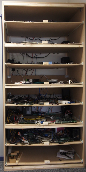 To meet the size constraints of Bootlin office, we had to make the lab fit in a 100cm wide, 75cm deep and 200cm high space. In order to achieve this, we decided to build the lab as a large home made cabinet, with a number of drawers to easily access, change or replace the boards hosted in the lab. As some of our boards provide PCIe connectors, we needed to provide enough height for each drawer, and after doing a few measurements, decided that a 25cm height for our drawers would be fine. With a total height of 200cm, this gives a maximum of 8 drawers.
In addition, it turns out that most of our boards powered by ATX power supplies are rather large in size, while the ones powered by regular power adapters are usually much smaller. In order to simplify the overall design, we decided that all large boards would be grouped together on a given set of drawers, and all small boards would be grouped together on another set of drawers: i.e we would not mix large and small boards in the same drawer. With the 100cm x 75cm size limitation, this meant a drawer for small boards could host up to 8 boards, while a drawer for large boards could host up to 4 boards. From the spreadsheet containing all the boards supposed to be in the lab, we eventually decided there would be 3 large drawers for up to 12 large boards and 5 small drawers for up to 40 small or medium-sized boards.
Furthermore, since the lab will host a server and a lot of boards and power supplies, potentially producing a lot of heat, we have to keep the lab as open as it can be while making sure it is strong enough to hold the drawers. We ended up building our own cabinet, made of wood bought from the local hardware store.
We also want the server to be part of the lab. We already have a small piece of wood to strengthen the lab between the fourth and sixth drawers we could use to fix the server. We decided to give a mini-PC (NUC-like) a try, because, after all, it’s only communicating with the serial of each board and serving files to them. Thus, everything related to the server is fixed and wired behind the lab.
Make the lab autonomous
What continuous integration for the Linux kernel typically needs are control of:
- the power for each board
- serial port connection
- a way to send files to test, typically the kernel image and associated files
In Bootlin lab, these different tasks are handled by a dedicated server, itself hosted in the lab.
Serial port control
Serial connections are mostly handled via USB on the server side but there are many different connectors on the target side (in our lab, we have 6 different connectors: DE9, microUSB, miniUSB, 2.54″ male pins, 2.54″ female pins and USB-B). Therefore, our server has to have a physical connection with each of the 50 boards present in the lab. The need for USB hubs is then obvious.
Since we want as few cables connecting the server and the drawers as possible, we decided to have one USB hub per drawer, be it a large drawer or a small drawer. In a small drawer, up to 8 boards can be present, meaning the hub needs at least 8 USB ports. In a large drawer, up to 4 serial connections can be needed so smaller and more common USB hubs can do the work. Since the serial connection may draw some current on the USB port, we wanted all of our USB hubs to be powered with a dedicated power supply.
All USB hubs are then connected to a main USB hub which in turn is connected to our server.
Power supply control
Our server needs to control each board’s power to be able to automatically power on or off a board. It will power on the board when it needs to test a new kernel on it and power it off at the end of the test or when the kernel has frozen or could not boot at all.
In terms of power supplies, we initially investigated using Ethernet-controlled multi-sockets (also called Switched PDU), such as this device. Unfortunately, these devices are quite expensive, and also often don’t provide the most appropriate connector to plug the cheap 5V/12V power adapters used by most boards.
So, instead, and following a suggestion from Kevin Hilman (one of KernelCI’s founder and maintainer), we decided to use regular ATX power supplies. They have the advantage of being inexpensive, and providing enough power for multiple boards and all their peripherals, potentially including hard drives or other power-hungry peripherals. ATX power supplies also have a pin, called PS_ON#, which when tied to the ground, powers up the ATX power supply. This easily allows to turn an ATX power supply on or off.
In conjunction with the ATX power supplies, we have a selected Ethernet-controlled relay board, the Devantech ETH008, which contains 8 relays that can be remote controlled over the network.
This gives us the following architecture:
- For the drawers with large boards powered by ATX directly, we have one ATX power supply per board. The PS_ON pin from the ATX power supply is cut and rewired to the Ethernet controlled relay. Thanks to the relay, we control if PS_ON is tied to the ground or not. If it’s tied to the ground, then the board boots, when it’s untied from the ground, the board is powered off.
- For the drawers with small boards, we have a single ATX power supply per drawer. The 12V and 5V rails from the ATX power supply are then dispatched through the 8-relay board, then connected to the appropriate boards, through DC barrel or mini-USB/micro-USB cables, depending on the board. The PS_ON is always tied to the ground, so those ATX power supplies are constantly on.
In addition, we have added a bit of over-voltage protection, by adding transient-voltage-suppression diodes for each voltage output in each drawer. These diodes will absorb all the voltage when it exceeds the maximum authorized value and explode, and are connected in parallel in the circuit to protect.
Network connectivity
As part of the continuous integration process, most of our boards will have to fetch the Linux kernel to test (and potentially other related files) over the network through TFTP. So we need all boards to be connected to the server running the continuous integration software.
Since a single 52 port switch is both fairly expensive, and not very convenient in terms of wiring in our situation, we instead opted for adding 8-port Gigabit switches to each drawer, all of them being connected via a central 16-port Gigabit switch located at the back of the home made cabinet. This central switch not only connects the per-drawer switches, but also the server running the continuous integration software, and the wider Internet.
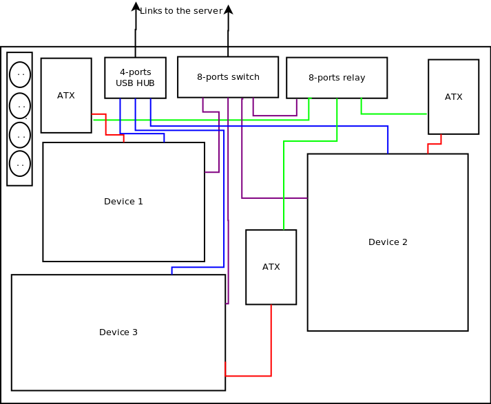
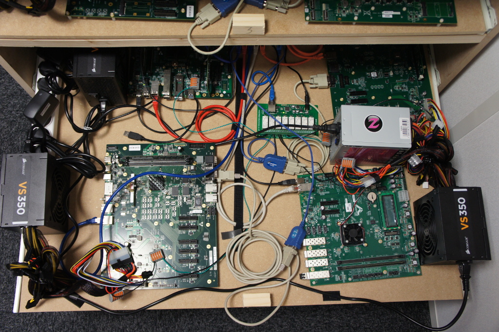
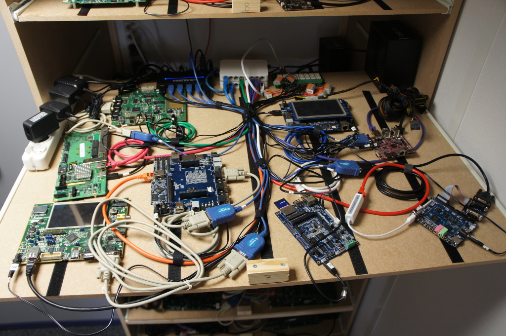
In-drawer architecture: large boards
A drawer designed for large boards, powered by an ATX power supply contains the following components:
- Up to four boards
- Four ATX power-supplies, with their PS_ON# connected to an 8-port relay controller. Only 4 of the 8 ports are used on the relay.
- One 8-port Ethernet-controlled relay board.
- One 4-port USB hub, connecting to the serial ports of the four boards.
- One 8-port Ethernet switch, with 4 ports used to connect to the boards, one port used to connect to the relay board, and one port used for the upstream link.
- One power strip to power the different components.
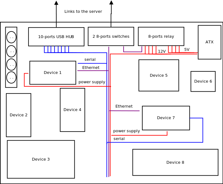
In drawer architecture: small boards
A drawer designed for small boards contains the following components:
- Up to eight boards
- One ATX power-supply, with its 5V and 12V rails going through the 8-port relay controller. All ports in the relay are used when 8 boards are present.
- One 8-port Ethernet-controlled relay board.
- One 10-port USB hub, connecting to the serial ports of the eight boards.
- Two 8-port Ethernet switches, connecting the 8 boards, the relay board and an upstream link.
- One power strip to power the different components.
Server
At the back of the home made cabinet, a mini PC runs the continuous integration software, that we will discuss in a future blog post. This mini PC is connected to:
- A main 16-port Gigabit switch, itself connected to all the Gigabit switches in the different drawers
- A main USB hub, itself connected to all the USB hubs in the different drawers
As expected, this allows the server to control the power of the different boards, access their serial port, and provide network connectivity.
Detailed component list
If you’re interested by the specific components we’ve used for our lab, here is the complete list, with the relevant links:
- standard DC barrel, to power most of boards,
- microUSB cables, to power other boards,
- two-sided scratch band,
- one-sided loop or hook scratch, one-sided glued, to fix hardware to drawers,
- ATX power supply
- Wire connector, to split wires without soldering,
- 10-ports USB hub, for serial connections on small drawers,
- 8-ports Ethernet-controlled relay, to control power for each board,
- 8-ports Ethernet switches,
- 4-ports USB hub, for serial connections on big drawers,
- 4-pins Molex to SATA connector, used as an extension cord for splitting outputs from ATX power supply instead of cutting the ATX power supply’s wires for small drawers,
- 20-pins Molex extension cord, used as an extension cord for splitting outputs from ATX power supply instead of cutting the ATX power supply’s wires for big drawers,
- 18 AWG cable, to split outputs of the ATX power supplies,
- 16-ports switch, used as the main switch,
- Mini PC, used as the server with 4 GB of RAM and a 120GB SSD,
- 12V power supply for Ethernet-controlled relay
- And also: Ethernet cables, wood panels, drawer slides, transient voltage suppression diodes, serial cables and power strips.
Conclusion
Hopefully, sharing these details about the hardware architecture of our board farm will help others to create a similar automated testing infrastructure. We are of course welcoming feedback on this hardware architecture!
Stay tuned for our next blog post about the software architecture of our board farm.