After showing how to build a minimal Linux system for the STM32MP157 platform, and how to connect and use an I2C based pressure/temperature/humidity sensor, we are now going to enable Qt5 and run some example graphical Qt5 applications. This is a necessary requirement before developing our own Qt5 application, which will be the topic of the next article in this series.
List of articles in this series:
- Building a Linux system for the STM32MP1: basic system
- Building a Linux system for the STM32MP1: connecting an I2C sensor
- Building a Linux system for the STM32MP1: enabling Qt5 for graphical applications
- Building a Linux system for the STM32MP1: setting up a Qt5 application development environment
- Building a Linux system for the STM32MP1: developing a Qt5 graphical application
- Building a Linux system for the STM32MP1: implementing factory flashing
- Building a Linux system for the STM32MP1: remote firmware updates
Display support in the Linux kernel
First of all, it is very important to distinguish the display controller from the GPU, as many people getting started with embedded systems and Linux tend to confuse both, while they are completely different things, both in terms of functionality and software support.
A display controller is an hardware block that takes the content of a memory area containing values representing the color of all pixels on your screen (a framebuffer) and sends it out to a display panel over hardware interfaces such as HDMI, DisplayPort, parallel interfaces or MIPI DSI. Some display controllers can take several framebuffers as input and compose them, potentially rescaling the size of some of them, and overlaying them with transparency. For example, some display controllers can take a framebuffer containing video frames, overlay another framebuffer that contains transparent pixels (to see the video) and some other pixels showing the UI of a video player, and another framebuffer overlayed on top of the two other ones that contains the mouse cursor. There are no 3D rendering or OpenGL operations involved: a display controller’s job is purely about taking framebuffer(s) contents and showing them on a display.
A GPU (or Graphics Processing Unit) is a very flexible programmable hardware unit, which among other things can be used to implement the OpenGL 3D rendering API, but also other APIs such as OpenCL. OpenGL and a GPU allow to offload in hardware the complex calculations that need to be done to render a 3D scene into a framebuffer of pixels. But a GPU by itself is not responsible at all for displaying on a screen what was rendered: it is the responsibility of a display controller.
Some system-on-chips only have a display controller, and no GPU at all, so you can display contents on one or several display panels, but you cannot benefit from hardware acceleration for 3D rendering. There are also use-cases where GPUs are used, but never to render anything looking like a 3D scene: that is for example the use-case for the OpenCL API, which allows to leverage the processing power of GPUs for general purpose programming.
In Linux, both display controllers and GPUs are managed by a Linux kernel subsystem called DRM, for Direct Rendering Manager. The DRM drivers are located in drivers/gpu/drm in the Linux kernel source code. If the hardware also has a GPU in addition to the display controller, then the most significant part of handling the GPU is done in user-space libraries implementing OpenGL. In the open-source world, the de-facto standard OpenGL implementation is Mesa3D, which has support for a number of different GPUs. From a GPU driver perspective, the kernel mainly serves as a way for the user-space OpenGL library to allocate buffers and send commands to the GPU.
The STM32MP15 has both a display controller and a GPU, but in this blog post, we are only going to make use of the display controller. The Linux kernel DRM driver used for the display controller of the STM32MP15 is in drivers/gpu/drm/stm. The driver can be enabled using the CONFIG_DRM_STM kernel configuration option.
In addition, the display panel used on the STM32MP15 Discovery Kit is connected to the SoC using the MIPI DSI interface. The STM32MP15 SoC contains a DSI encoder hardware block from Synopsys, and a glue driver for the DSI encoder is available in drivers/gpu/drm/stm/dw_mipi_dsi-stm.c and can be enabled using the CONFIG_DRM_STM_DSI option.
It turns out that the kernel configuration file we’re using since our initial blog post does have both of these options enabled, as well as the option providing support for the specific DSI display panel used on the Discovery board:
CONFIG_DRM=y
CONFIG_DRM_STM=y
CONFIG_DRM_STM_DSI=y
CONFIG_DRM_PANEL_ORISETECH_OTM8009A=y
The user-space interface of DRM is detailed in its documentation. Typical applications do not use directly this interface, and instead rely on a display stack in user-space such as X.org or Wayland, or directly on a graphical toolkit like Qt.
In addition, the DRM subsystem implements a compatibility layer that emulates the Linux framebuffer user-space interface, as documented in framebuffer.txt. This allows to support older applications/libraries that don’t use DRM directly.
In our case, we are going to use the Qt graphical toolkit, and on embedded Linux systems, it has four main display backends: eglfs (which requires an OpenGL/EGL graphics stack), linuxfb (which uses a simple legacy framebuffer interface), wayland (for Wayland, obviously) and xcb (for X.org). To keep things simple for this series and blog post, and because we don’t require OpenGL support, we will use the linuxfb backend.
Touch panel support in the Linux kernel
The Linux kernel has a subsystem called input for all input devices, such as keyboards, mice, touchscreens, joysticks and more. Its user-space interface is described in details in the kernel documentation, and this interface is used by most display stacks in user-space. For example, Qt supports it through the backend called evdev.
In terms of hardware, the Discovery Kit display panel integrates a touch panel that uses a Focaltech FT6236 controller, connected over I2C. The Device Tree describes this touch panel device as follows:
&i2c1 {
        touchscreen@2a {
                compatible = "focaltech,ft6236";
                reg = <0x2a>;
                interrupts = <2 2>;
                interrupt-parent = <&gpiof>;
                interrupt-controller;
                touchscreen-size-x = <480>;
                touchscreen-size-y = <800>;
                status = "okay";
        };
};
The corresponding driver in the Linux kernel is drivers/input/touchscreen/edt-ft5x06.c, which can be enabled using the CONFIG_TOUCHSCREEN_EDT_FT5X06 kernel configuration option.
The input subsystem, its evdev interface, and the specific driver for our touch panel are all already enabled in the kernel configuration file we are using since our first blog post:
CONFIG_INPUT_EVDEV=y
CONFIG_INPUT_TOUCHSCREEN=y
CONFIG_TOUCHSCREEN_EDT_FT5X06=y
Basic testing of the display and touch panel
To test the touch panel and display, we can start with very simple tools instead of using directly a complex graphical stack. The tools we recommend to use are:
- The evtest program from the project of the same name. It allows to dump input events from any input device.
- The modetest program that comes from the libdrm project. It allows to test a display by showing some pre-defined pictures.
Let’s add those two software components in our Buildroot configuration: go to menuconfig, and enable the BR2_PACKAGE_EVTEST, BR2_PACKAGE_LIBDRM and BR2_PACKAGE_LIBDRM_INSTALL_TESTS options. Restart the build of the Buildroot system by running make, and once the build has completed, write the new SD card image to your SD card.
On the system, let’s have a look at available input device (output edited to fit in the blog post):
# ls -l /sys/class/input/
event0 -> ...platform/soc/40012000.i2c/i2c-0/0-002a/input/input0/event0
event1 -> ...platform/soc/5c002000.i2c/i2c-2/2-0033/5c002000.i2c:stpmic@33:onkey/input/input2/event1
input0 -> ...platform/soc/40012000.i2c/i2c-0/0-002a/input/input0
input2 -> ...platform/soc/5c002000.i2c/i2c-2/2-0033/5c002000.i2c:stpmic@33:onkey/input/input2
So input0 is our touch panel (connected on I2C bus 0, at address 0x2A), and event0 is its evdev user-space interface. This evdev interface is accessible through the /dev/input/event0 device file:
# ls -l /dev/input/event0
crw-------    1 root     root       13,  64 Jan  1  1970 /dev/input/event0
Now we can run evtest. With no arguments, it shows the list of available input devices, their name, and allows use to chose the one we would like to test:
# evtest
No device specified, trying to scan all of /dev/input/event*
Available devices:
/dev/input/event0:	generic ft5x06 (11)
/dev/input/event1:	pmic_onkey
Select the device event number [0-1]: 0
Once evtest is running, press the touch panel, and you will see events reported like this:
Event: time 946685148.736402, type 3 (EV_ABS), code 57 (ABS_MT_TRACKING_ID), value 0
Event: time 946685148.736402, type 3 (EV_ABS), code 53 (ABS_MT_POSITION_X), value 259
Event: time 946685148.736402, type 3 (EV_ABS), code 54 (ABS_MT_POSITION_Y), value 428
Event: time 946685148.736402, type 1 (EV_KEY), code 330 (BTN_TOUCH), value 1
Event: time 946685148.736402, type 3 (EV_ABS), code 0 (ABS_X), value 259
Event: time 946685148.736402, type 3 (EV_ABS), code 1 (ABS_Y), value 428
These events show the coordinates of the press, and the actual press event (BTN_TOUCH).
With the touch panel working, let’s move on to the display. In fact, you know the display is already working: the fbcon kernel driver provides a console over the framebuffer, which is why you are seeing the Linux kernel messages on the screen. Nevertheless, let’s use the modetest program from libdrm. Without any argument, it just prints out some details about the available display hardware. First the encoders:
Encoders:
id	crtc	type	possible crtcs	possible clones
28	0	DPI	0x00000001	0x00000000
30	33	DSI	0x00000001	0x00000000
So the display controller has two encoders: one with a DPI interface (i.e parallel RGB interface) and one with a (MIPI) DSI interface.
Then, we have the list of connectors:
Connectors:
id	encoder	status		name		size (mm)	modes	encoders
29	0	disconnected	HDMI-A-1       	0x0		0	28
[..]
31	30	connected	DSI-1          	52x86		1	30
  modes:
	name refresh (Hz) hdisp hss hse htot vdisp vss vse vtot)
  480x800 50 480 578 610 708 800 815 825 839 29700 flags: ; type: preferred, driver
We have a HDMI connector, which can be used with the encoder of id 28, that is the DPI encoder. Indeed, the RGB parallel interface of the STM32 processor is fed on the board into an HDMI transceiver, that goes out with HDMI signals on connector CN9. So from the point of view of the SoC, it is a parallel RGB interface, but thanks to the HDMI transceiver on the Discovery board, it is in fact usable as an HDMI connector.
The second connector is the DSI connector, which can be used with encoder of id 30, i.e the DSI encoder, which makes sense.
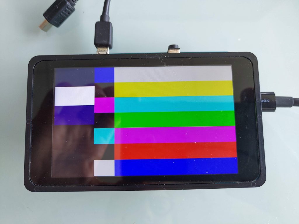
So let’s ask modetest to display its test picture on the DSI connector, which has id 31. The DSI panel resolution is 480×800, so we’ll use the following command:
# modetest -s 31:480x800
And voilà:
Now if we plug an HDMI screen to the HDMI connector, the modetest output about connector 29 changes as the connector is no longer disconnected:
Connectors:
id	encoder	status		name		size (mm)	modes	encoders
29	0	connected	HDMI-A-1       	520x290		11	28
  modes:
	name refresh (Hz) hdisp hss hse htot vdisp vss vse vtot)
  1280x720 60 1280 1390 1430 1650 720 725 730 750 74250 flags: phsync, pvsync; type: driver
  1280x720 60 1280 1390 1430 1650 720 725 730 750 74250 flags: phsync, pvsync; type: driver
  1280x720 50 1280 1720 1760 1980 720 725 730 750 74250 flags: phsync, pvsync; type: driver
  [...]
So we can ask modetest to display a 1280×720 picture on the HDMI screen:
# modetest -s 29:1280x720
Enabling Qt5 support in Buildroot
Now that we have successfully tested the display and touchscreen, it is time to move on and use a powerful graphical toolkit for embedded Linux systems: Qt. Qt is already packaged in Buildroot, and therefore very easy to add to our system, including some examples. Simply enable the following options in your Buildroot configuration:
BR2_PACKAGE_QT5, which enables Qt as a whole, and automatically selects the core Qt module called qt5baseBR2_PACKAGE_QT5BASE_GUI, which enables GUI support in qt5base. The linuxfb backend is automatically selected, but provided the appropriate dependencies are enabled, other display backends can be enabled as well. In our case, we’ll use the linuxfb backend so the default selection will work for us.BR2_PACKAGE_QT5BASE_WIDGETS, which enables the Qt5 Widget library, which allows to easily write graphical applications with buttons, text boxes, drop down lists and other familiar graphical widgetsBR2_PACKAGE_QT5BASE_EXAMPLES, to enable the example Qt5 applicationsBR2_PACKAGE_QT5BASE_FONTCONFIG, to enable the fontconfig support in Qt. This allows Qt to discover the fonts available on our system to render text.BR2_PACKAGE_DEJAVU, which will provide one font to render text. Without this, Qt applications would run, but no text would be rendered
Once these options are enabled, restart the build with make and rewrite the new image to your SD card.
Test Qt5 application
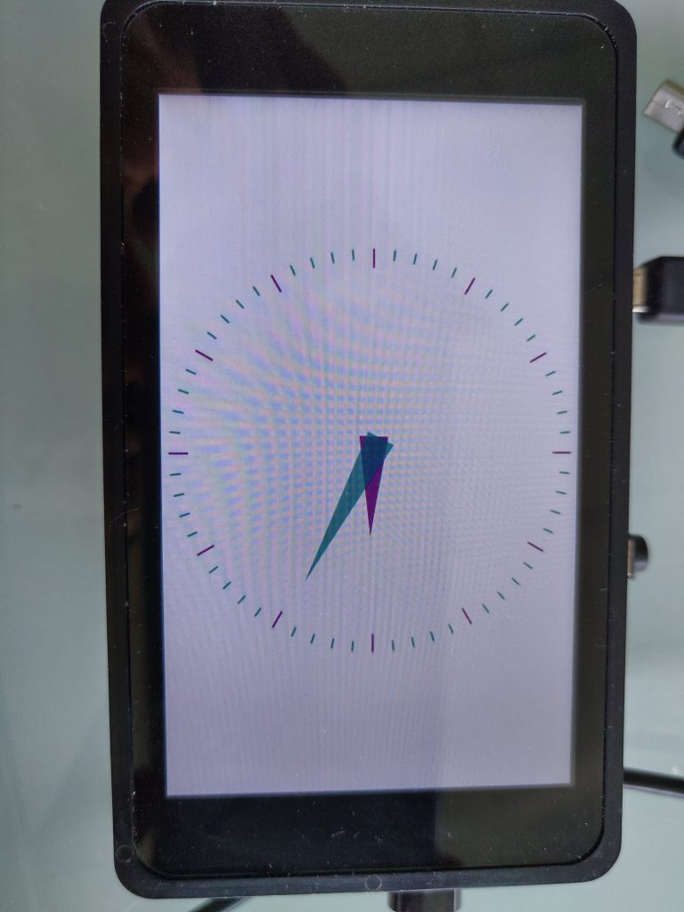
All the Qt examples are installed in /usr/lib/qt/examples/, so you can try all of them. Let’s start with the analogclock for example:
# /usr/lib/qt/examples/gui/analogclock/analogclock -platform linuxfb
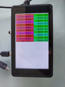
Then, another one which allows to test the touch panel:
# /usr/lib/qt/examples/widgets/scroller/graphicsview/graphicsview -platform linuxfb
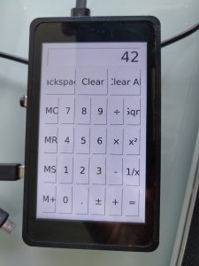
And a more “complete” and useful application, which as you can see does not fit very well on a 480×800 screen in portrait mode, but also allows to use the touchscreen:
# /usr/lib/qt/examples/widgets/widgets/calculator/calculator -platform linuxfb
Filesystem size
To conclude this article, let’s have a look at the size of our filesystem size. After a completely clean build (make clean all), Buildroot can generate a nice graph of the filesystem size using make graph-size. In our case, it generates the following graph:
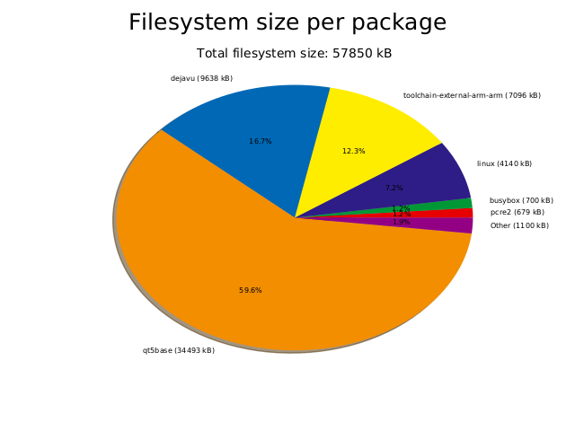
So the overall filesystem size is 58.7 MB, on which 34.4 MB come from Qt. But our Qt is compiled with examples, and the examples take up 16.7 MB (this is not visible on the graph, it was calculated by looking at the size of /usr/lib/qt/examples/) on the target). Also, the dejavu font package is quite large, with 9.6 MB.
Conclusion
You can find the exact Buildroot source code used to reproduce the system used in this article in the branch at 2019.02/stm32mp157-dk-blog-3.
In this article, we learned about how Linux manages display and input devices and how to test them with simple applications such as modetest and evtest. Then we looked at how to add the Qt library to our Buildroot configuration, and verify it is working using Qt example applications.
Our next blog post will cover how to build a real Qt application!
Just wanted to say thank you for these tutorials. I’ve spent a week being frustrated with Yocto and these have really helped. Looking forward to the next one!
Excellent article. You have taken a difficult subject and made it understandable.
Can you make an estimate of when you will have the next article posted? I can’t wait to see it.
If I use the open source version of Qt Creator, is it possible to cross-compile a Qt application for the MP1 on a Linux Intel desktop computer? Will you discuss that in your next article? And can you also give any tips on how one would debug the application? I am afraid that the only way to do either is to purchase the commercial version of Qt Creator, but that is really expensive.
I know that STM is going to update STM32CubeIDEr to support the MP1. Can it be used to debug a Qt based app?
Assuming it is impractical / expensive to develop and debug Qt application, Is GTK a viable tool for embedded linux applications? I think it might be possible to develop and debug a GTK app using STM32CubeIDE.
I hope to hear your thoughts on these subjects.
Hello ClarkS, and thanks for your comment and numerous questions.
We don’t have a specific date for publishing the next article, but we hope to have it done in the first half of September.
We are not super familiar with Qt Creator, but yes, you are definitely able to use it to cross-compile a Qt application for any embedded Linux based system, including the MP1. I don’t really see what you would absolutely need the commercial version of Qt Creator to be able to debug your application, I believe Qt Creator is fully open-source.
I am not familiar with the STM32Cube IDE (I generally try to avoid vendor-specific tools), but looking briefly at some details about it, it is basically an Eclipse IDE with additional plugins specific to STM32 development. So it can surely be used for regular embedded Linux development as well, as Eclipse is able to do cross-compilation and remote debugging.
Gtk is indeed an alternative to Qt, but I don’t see how using Gtk over Qt makes a difference in terms of being able to develop with the STM32Cube IDE.
When I launch the examples that using text this message is shown and the application doesn’t display texts.
QFontDatabase: Cannot find font directory /usr/lib/fonts.
Note that Qt no longer ships fonts. Deploy some (from https://dejavu-fonts.github.io/ for example) or switch to fontconfig.
I haven’t found the dejavu on menuconfig; seems that has been removed from Qt (on menuconfig Qt 5.11 is shown).
How I can solve this issue?
Our blog post clearly indicates that both BR2_PACKAGE_QT5BASE_FONTCONFIG and BR2_PACKAGE_DEJAVU should be enabled. Do you have both of these options enabled ? The former adds fontconfig support in Qt, while the latter adds the DejaVu fonts.
If you’re unsure, you can always check the branch at https://github.com/tpetazzoni/buildroot/commits/2019.02/stm32mp157-dk-blog-3 and do a build from there. As you can see in commit https://github.com/tpetazzoni/buildroot/commit/e670d7eee77d144ad9aff7a7f0b99aacbcdc45cd, we do enable fontconfig support in Qt and DejaVu.
Hope this helps!
Hey Thomas,
currently I’m trying to get familiar with ST32MP1 and linux. Your tutorials are a great help. Thank you very much.
I’m getting same error message as destmaster if i try to run examples using fonts. In my image the fonts can be found at /usr/share/fonts/dejavu. So I simply created a soft-link by “ln -s /usr/share/fonts/dejavu/ /usr/lib/fonts” and it works for now.
I’m excercising currently on the “v4.19-stm32mp-r1.5” branch. Not sure if thats the reason why.
Just as a note for others stumbling in a similiar situation.
Could you, please, clarify for me this part:
“Let’s add those two software components in our Buildroot configuration: go to menuconfig, and enable the BR2_PACKAGE_EVTEST, BR2_PACKAGE_LIBDRM and BR2_PACKAGE_LIBDRM_INSTALL_TESTS options.”
I execute:
$make menuconfig
but I cannot find a section where I can enable these options. There many others, but not these ones.
I did the first and second part of your article, and the BME280 sensor works fine.
Hi Alexis,
In “make menuconfig”, type “/” to search for parameters, as explained on the on-screen help.
Then look for each parameter without the “BR2_” prefix.
I hope this helps,
Cheers,
Michael.
Michael, Thank you. It did help. I figured out how to find via the search the locations of these options in the menuconfig.
Thank you for this great tutorial!
On a STM32MP1 DK2 board I can not enable touch.
linux.conf:
CONFIG_INPUT_EVDEV=y
CONFIG_INPUT_touchTOUCHSCREEN=y
CONFIG_TOUCHSCREEN_EDT_FT5X06=y
CONFIG_DRM=y
CONFIG_DRM_STM=y
CONFIG_DRM_STM_DSI=y
CONFIG_DRM_PANEL_ORISETECH_OTM8009A=y
CONFIG_DRM_SII902X=y
I am using buildroot 2020.02 based upon stm32mp157c_dk2_defconfig
Maybe someone can give me a hint. Thank you. Stefan
Hello Stefan. Glad to read that our series of tutorials is useful. Could you test first with the Buildroot branch provided as part of this blog post series? Then we can investigate why the touchscreen is not working with Buildroot 2020.02.
Ok Thomas; I followed your post 1:1 and: yes it works! Thank you!
My goal is to use the STM32MP1 SoM of bytesatwork
https://www.bytesatwork.io/wp-content/uploads/2019/12/Datasheet_byteENGINE_STM32MP1x-4.pdf
What is your reccomondation to use buildroot with this SoM?
See my project here and what I have tried so far…
https://1drv.ms/u/s!As18G4EAV66yq55fSavPIlnEzYaquA?e=SPfZHS
Cheers, Stefan
Congratulations for your project! Buildroot is platform-agnostic, so you can use Buildroot whatever platform, board or SoM you have chosen.
Hello, Thomas!
The same problem with touchscreen with buildroot 2020.05. It’s very intresting – why? May be in new versions it’s OK. But what with 2020.05?
Hi Thomas! First of all, thanks about this great tutorial! I’m also new at this embedded Linux universe, so I’m sorry about this noob question: is Qt5 free to use, even on commercial solutions? Thanks again!
Hi
No, with Qt5 you cannot create proprietary (it that’s what you meant… commercial applications can be free software) applications without getting their commercial license.
Cheers,
Michael.
Hi Michael, thanks! Yes, I meant proprietary solutions, no free software. So I think a good alternative would be GTK, right?
Thanks again!
Right, GTK could be a solution. People are using EFL too, which could be a worthy solution too…
Great tutorials!
I had to use GCC v8 instead of GCC v9 to compile Qt5. Here’s the command line for anyone that wants to install gcc 8 along side the build-essentials GCC and make it the auto option:
update-alternatives –install /usr/bin/gcc gcc /usr/bin/gcc-8 1 –slave /usr/bin/g++ g++ /usr/bin/g++-8
Link to forum post by someone else with the issue:
https://forums.gentoo.org/viewtopic-p-8336448.html?sid=527bc0cd156b3ad40d11584f1601a096
Hi I tried this cmd but got error
update-alternatives –install /usr/bin/gcc gcc /usr/bin/gcc-8 1 –slave /usr/bin/g++ g++ /usr/bin/g++-8
update-alternatives: error: unknown argument ‘–install’
You can also use a more recent version of Buildroot, which should have these GCC 9.x version issue fixed.
I want to put the background image in Qpainter in the buildroot you explained, but it is displayed only in white and the image does not come out.
QT5 has added all of the things on this page in buildroot, so I wonder if there is anything I need to add.
Usually what is missing in this sort of cases is Qt support for the specific picture format you’re using. I.e, check BR2_PACKAGE_QT5BASE_GIF, BR2_PACKAGE_QT5BASE_JPEG or BR2_PACKAGE_QT5BASE_PNG depending on the image format you have.
Thank you for answer.
====================================
BR2_PACKAGE_QT5BASE_GIF=y
BR2_PACKAGE_QT5BASE_JPEG=y
BR2_PACKAGE_QT5BASE_PNG=y
=====================================
Even after adding it. .config file label->setPixmap(m_image);
ui->label->show();
========================================
If you put the resource image ABC.png file on the stm32mp157c-dk2 board in the same path as the working directory, shouldn’t the image be displayed??
Only a white screen appears.
I made a mistake.
If I run it again after performing make clean all, the image is uploaded well.
Thank you again.
I have one more question.
I would like to know if there is a way to get the LCD screen to come out through HDMI. Currently, only the LCD screen is displayed.
How do I make the duplicate screen appear on both the LCD screen and the HDMI screen?
Hello
I want to get the screen from stm32mp157c-dk2 board to HDMI.
I am using 2019.02/stm32mp157-dk-blog-3. by downloading it now
[ buildroot version : 2019.02 ]
If you input the following on the console, you can see the screen through HDMI.
[ modetest -s 29:1280×720 ]
QT5.11.2 Can you give me some advice on what to do to get the HDMI output from the program?
Hi Thomas,
Thank you for putting out this tutorial. It is very helpful.
Would you please help me out with this problem I have?
I try to build stm32mp157a_dk1_defconfig. I enable BR2_PACKAGE_QT5 AND BR2_PACKAGE_QT5BASE as well as other QT5 package.
However, when I make and go to make menuconfig –> search for these packages it keeps showing me these options [=n]. I try to many way to enable these options but still I do not see QT5 in menuconfig.
Please help
In Buildroot upstream, the defconfigs are minimal, so when you do “make stm32mp157a_dk1_defconfig”, it configures a very minimal system, and also a minimal toolchain, which for example doesn’t have C++ support. But Qt is implemented in C++, so if your toolchain does not have C++ support, Qt is not visible in menuconfig.
So after running “make stm32mp157a_dk1_defconfig”, you need in menuconfig, in the Toolchain menu, to enable C++ support and wchar support.
Alternatively, I would like to suggest you to look at https://github.com/bootlin/buildroot-external-st, which a BR2_EXTERNAL for Buildroot that has demo configurations for the STM32MP1 platforms that include Qt, with OpenGL support, and many other useful features. Have a look, it will probably be helpful.
So I’m trying to use an external LCD screen with multitouch with the stm32mp157d-dk1.
Using the demo OS from ST, openSTLinux, the screen and touch works fine. But when trying to use this method of compiling with buildroot, I can’t get the touchscreen to work. I know is a goodix device using an i2c to usb interface. I have installed all drivers I can possibly think that would make it work without luck.
When I touch the panel, the USB disconnects and reconnects it again.
[ 20.079074] usb 1-1.1: USB disconnect, device number 3
[ 20.518036] usb 1-1.1: new full-speed USB device number 4 using ehci-platform
[ 20.682786] input: wch.cn USB2IIC_CTP_CONTROL as /devices/platform/soc/5800d000.usb/usb1/1-1/1-1.1/1-1.1:1.0/0003:1A86:E5E3.0002/input/input2
[ 20.701971] hid-multitouch 0003:1A86:E5E3.0002: input: USB HID v1.00 Device [wch.cn USB2IIC_CTP_CONTROL] on usb-5800d000.usb-1.1/input0
Please use https://github.com/bootlin/buildroot-external-st instead of what is described in this post (which is quite old).
Hi Thomas,
Thank you for this excellent tutorial. It is very helpful.
when I run qt examples in my case, apps aren’t fullscreen and I cann’t change it, why? (The following pictures show this fact)
https://ibb.co/s2RNfSw
https://ibb.co/LhDLbYp
https://ibb.co/bK5VGP9
On which platform are you running this? Is the size 480×800 that you pass on the command line correct compared to the size of your screen?
Also, please be aware that this blog post is *very* old. If you want to use Buildroot on ST platforms these days and want an easy starting point, I recommend checking our https://github.com/bootlin/buildroot-external-st project.
my platform: STM32MP157F-DK2
yes size of screen is: 480×800 and if I don’t pass any parameters, the output is the same.
Hi Thomas Petazzoni
thank you so much for this tutorial
I used https://github.com/bootlin/buildroot-external-st and now I want to chage my lcd orientation by 90 degrees how can I do that?
Hello – thank you for these great tutorials. They’ve all been going well so far, until I reached the modetest command. When I try to run “modetest -s 31:480×800”, I receive the response “-sh: modetest: not found”. I have ensured that BR2_PACKAGE_EVTEST, BR2_PACKAGE_LIBDRM and BR2_PACKAGE_LIBDRM_INSTALL_TESTS options are all enabled in menuconfig. Please help. Thank you!
Hello – I am running into this “messenne_twisters” build failure related to Qt5, described here – https://codereview.qt-project.org/c/qt/qtbase/+/245425. I tried manually editing the qrandom.cpp file in the /buildroot/dl/qt5base/ tar file but it didn’t fix the issue. Any suggestions?
Related to my previous post, I am running into this exact problem… https://github.com/InBetweenNames/gentooLTO/issues/286
That page states it should be OK with Qt 5.12 (but fails with Qt 5.11). How do I change to Qt 5.12?
Thank you.