Bootlin training courses on NXP i.MX93 FRDM, and NXP Registered Partner status

NXP i.MX93 FRDMBootlin’s training courses, along with our freely available training materials, have been a cornerstone of the embedded Linux ecosystem for over 20 years. During this time, we have continuously expanded and refined our training portfolio, both to cover new technical topics and to adopt new hardware platforms for our practical lab sessions.

Today, we are excited to share two closely related milestones: the availability of our major training courses on an NXP platform, and Bootlin becoming an official NXP Registered Partner. These two developments reflect our long-standing collaboration with NXP technologies and our commitment to supporting engineers working with i.MX platforms.

NXP i.MX93 FRDM
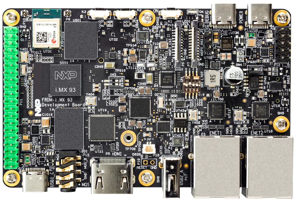
As part of our ongoing effort to improve and modernize our training offering, our three most popular training courses are now available on the NXP i.MX93 FRDM platform:

These courses are available immediately, and the corresponding training materials have already been published and can be freely accessed on our website. As usual, the courses can be delivered as public online sessions, private online sessions, or private on-site sessions, depending on your needs. If you are interested in attending one of these training sessions, or in organizing a private training for your team on the NXP i.MX93 FRDM platform, feel free to contact us to discuss your needs or consult our training schedule for upcoming public sessions.

Beyond training, Bootlin’s core business is providing engineering services to help organizations worldwide design and build products based on embedded Linux. Over the years, we have supported a large number of customers using NXP-based platforms—including i.MX6, i.MX7, i.MX8, and i.MX9, across a wide range of topics such as board bring-up, Linux BSP development, Linux kernel porting and driver development, Yocto Project or Buildroot integration, secure boot, and more.

Our new status as an NXP Registered Partner formally recognizes this extensive experience and collaboration. It also reinforces our ability to support customers with up-to-date expertise on NXP technologies, from early platform evaluation to production-ready systems. Check out our NXP partner page for more details on our expertise and offering related to NXP products.

In this context, making the NXP i.MX93 FRDM board a first-class platform for our training courses is a natural step. It allows engineers to train on modern NXP hardware that closely matches what they use in real-world projects, making the learning experience more practical and immediately applicable.

Eight channels audio on i.MX7 with PCM3168

Toradex Colibri i.MX7Bootlin engineer Alexandre Belloni recently worked on a custom carrier board for a Colibri iMX7 system-on-module from Toradex. This system-on-module obviously uses the i.MX7 ARM processor from Freescale/NXP.

While the module includes an SGTL5000 codec, one of the requirements for that project was to handle up to eight audio channels. The SGTL5000 uses I²S and handles only two channels.

I2S

I2S timing diagram from the SGTL5000 datasheet

Thankfully, the i.MX7 has multiple audio interfaces and one is fully available on the SODIMM connector of the Colibri iMX7. A TI PCM3168 was chosen for the carrier board and is connected to the second Synchronous Audio Interface (SAI2) of the i.MX7. This codec can handle up to 8 output channels and 6 input channels. It can take multiple formats as its input but TDM takes the smaller number of signals (4 signals: bit clock, word clock, data input and data output).


TDM timing diagram from the PCM3168 datasheet

The current Linux long term support version is 4.9 and was chosen for this project. It has support for both the i.MX7 SAI (sound/soc/fsl/fsl_sai.c) and the PCM3168 (sound/soc/codecs/pcm3168a.c). That’s two of the three components that are needed, the last one being the driver linking both by describing the topology of the “sound card”. In order to keep the custom code to the minimum, there is an existing generic driver called simple-card (sound/soc/generic/simple-card.c). It is always worth trying to use it unless something really specific prevents that. Using it was as simple as writing the following DT node:

        board_sound {
                compatible = "simple-audio-card";
                simple-audio-card,name = "imx7-pcm3168";
                simple-audio-card,widgets =
                        "Speaker", "Channel1out",
                        "Speaker", "Channel2out",
                        "Speaker", "Channel3out",
                        "Speaker", "Channel4out",
                        "Microphone", "Channel1in",
                        "Microphone", "Channel2in",
                        "Microphone", "Channel3in",
                        "Microphone", "Channel4in";
                simple-audio-card,routing =
                        "Channel1out", "AOUT1L",
                        "Channel2out", "AOUT1R",
                        "Channel3out", "AOUT2L",
                        "Channel4out", "AOUT2R",
                        "Channel1in", "AIN1L",
                        "Channel2in", "AIN1R",
                        "Channel3in", "AIN2L",
                        "Channel4in", "AIN2R";

                simple-audio-card,dai-link@0 {
                        format = "left_j";
                        bitclock-master = <&pcm3168_dac>;
                        frame-master = <&pcm3168_dac>;
                        frame-inversion;

                        cpu {
                                sound-dai = <&sai2>;
                                dai-tdm-slot-num = <8>;
                                dai-tdm-slot-width = <32>;
                        };

                        pcm3168_dac: codec {
                                sound-dai = <&pcm3168 0>;
                                clocks = <&codec_osc>;
                        };
                };

                simple-audio-card,dai-link@2 {
                        format = "left_j";
                        bitclock-master = <&pcm3168_adc>;
                        frame-master = <&pcm3168_adc>;

                        cpu {
                                sound-dai = <&sai2>;
                                dai-tdm-slot-num = <8>;
                                dai-tdm-slot-width = <32>;
                        };

                        pcm3168_adc: codec {
                                sound-dai = <&pcm3168 1>;
                                clocks = <&codec_osc>;
                        };
                };
        };

There are multiple things of interest:

  • Only 4 input channels and 4 output channels are routed because the carrier board only had that wired.
  • There are two DAI links because the pcm3168 driver exposes inputs and outputs separately
  • As per the PCM3168 datasheet:
    • left justified mode is used
    • dai-tdm-slot-num is set to 8 even though only 4 are actually used
    • dai-tdm-slot-width is set to 32 because the codec takes 24-bit samples but requires 32 clocks per sample (this is solved later in userspace)
    • The codec is master which is usually best regarding clock accuracy, especially since the various SoMs on the market almost never expose the audio clock on the carrier board interface. Here, a crystal was used to clock the PCM3168.

The PCM3168 codec is added under the ecspi3 node as that is where it is connected:

&ecspi3 {
        pcm3168: codec@0 {
                compatible = "ti,pcm3168a";
                reg = <0>;
                spi-max-frequency = <1000000>;
                clocks = <&codec_osc>;
                clock-names = "scki";
                #sound-dai-cells = <1>;
                VDD1-supply = <&reg_module_3v3>;
                VDD2-supply = <&reg_module_3v3>;
                VCCAD1-supply = <&reg_board_5v0>;
                VCCAD2-supply = <&reg_board_5v0>;
                VCCDA1-supply = <&reg_board_5v0>;
                VCCDA2-supply = <&reg_board_5v0>;
        };
};

#sound-dai-cells is what allows to select between the input and output interfaces.

On top of that, multiple issues had to be fixed:

Finally, an ALSA configuration file (/usr/share/alsa/cards/imx7-pcm3168.conf) was written to ensure samples sent to the card are in the proper format, S32_LE. 24-bit samples will simply have zeroes in the least significant byte. For 32-bit samples, the codec will properly ignore the least significant byte.
Also this describes that the first subdevice is the playback (output) device and the second subdevice is the capture (input) device.

imx7-pcm3168.pcm.default {
	@args [ CARD ]
	@args.CARD {
		type string
	}
	type asym
	playback.pcm {
		type plug
		slave {
			pcm {
				type hw
				card $CARD
				device 0
			}
			format S32_LE
			rate 48000
			channels 4
		}
	}
	capture.pcm {
		type plug
		slave {
			pcm {
				type hw
				card $CARD
				device 1
			}
			format S32_LE
			rate 48000
			channels 4
		}
	}
}

On top of that, the dmix and dsnoop ALSA plugins can be used to separate channels.

To conclude, this shows that it is possible to easily leverage existing code to integrate an audio codec in a design by simply writing a device tree snippet and maybe an ALSA configuration file if necessary.