Eight channels audio on i.MX7 with PCM3168

Toradex Colibri i.MX7
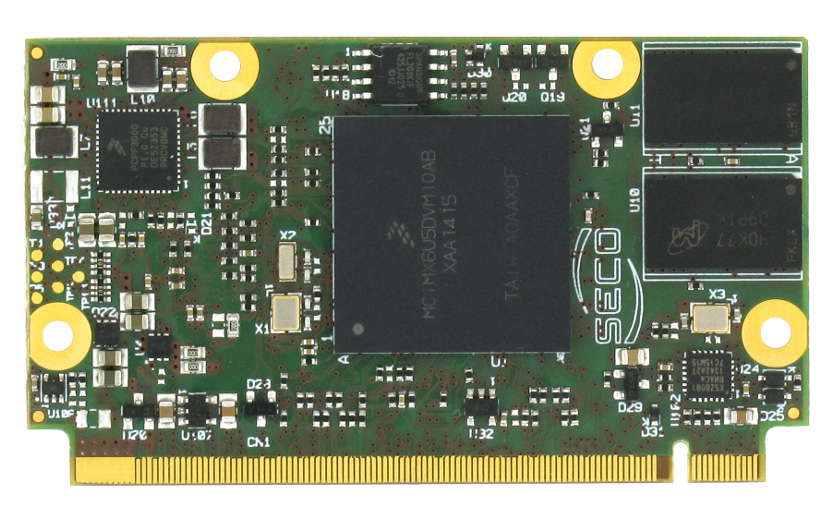
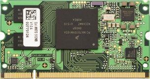
Bootlin engineer Alexandre Belloni recently worked on a custom carrier board for a Colibri iMX7 system-on-module from Toradex. This system-on-module obviously uses the i.MX7 ARM processor from Freescale/NXP.

While the module includes an SGTL5000 codec, one of the requirements for that project was to handle up to eight audio channels. The SGTL5000 uses I²S and handles only two channels.

I2S

I2S timing diagram from the SGTL5000 datasheet

Thankfully, the i.MX7 has multiple audio interfaces and one is fully available on the SODIMM connector of the Colibri iMX7. A TI PCM3168 was chosen for the carrier board and is connected to the second Synchronous Audio Interface (SAI2) of the i.MX7. This codec can handle up to 8 output channels and 6 input channels. It can take multiple formats as its input but TDM takes the smaller number of signals (4 signals: bit clock, word clock, data input and data output).


TDM timing diagram from the PCM3168 datasheet

The current Linux long term support version is 4.9 and was chosen for this project. It has support for both the i.MX7 SAI (sound/soc/fsl/fsl_sai.c) and the PCM3168 (sound/soc/codecs/pcm3168a.c). That’s two of the three components that are needed, the last one being the driver linking both by describing the topology of the “sound card”. In order to keep the custom code to the minimum, there is an existing generic driver called simple-card (sound/soc/generic/simple-card.c). It is always worth trying to use it unless something really specific prevents that. Using it was as simple as writing the following DT node:

        board_sound {
                compatible = "simple-audio-card";
                simple-audio-card,name = "imx7-pcm3168";
                simple-audio-card,widgets =
                        "Speaker", "Channel1out",
                        "Speaker", "Channel2out",
                        "Speaker", "Channel3out",
                        "Speaker", "Channel4out",
                        "Microphone", "Channel1in",
                        "Microphone", "Channel2in",
                        "Microphone", "Channel3in",
                        "Microphone", "Channel4in";
                simple-audio-card,routing =
                        "Channel1out", "AOUT1L",
                        "Channel2out", "AOUT1R",
                        "Channel3out", "AOUT2L",
                        "Channel4out", "AOUT2R",
                        "Channel1in", "AIN1L",
                        "Channel2in", "AIN1R",
                        "Channel3in", "AIN2L",
                        "Channel4in", "AIN2R";

                simple-audio-card,dai-link@0 {
                        format = "left_j";
                        bitclock-master = <&pcm3168_dac>;
                        frame-master = <&pcm3168_dac>;
                        frame-inversion;

                        cpu {
                                sound-dai = <&sai2>;
                                dai-tdm-slot-num = <8>;
                                dai-tdm-slot-width = <32>;
                        };

                        pcm3168_dac: codec {
                                sound-dai = <&pcm3168 0>;
                                clocks = <&codec_osc>;
                        };
                };

                simple-audio-card,dai-link@2 {
                        format = "left_j";
                        bitclock-master = <&pcm3168_adc>;
                        frame-master = <&pcm3168_adc>;

                        cpu {
                                sound-dai = <&sai2>;
                                dai-tdm-slot-num = <8>;
                                dai-tdm-slot-width = <32>;
                        };

                        pcm3168_adc: codec {
                                sound-dai = <&pcm3168 1>;
                                clocks = <&codec_osc>;
                        };
                };
        };

There are multiple things of interest:

  • Only 4 input channels and 4 output channels are routed because the carrier board only had that wired.
  • There are two DAI links because the pcm3168 driver exposes inputs and outputs separately
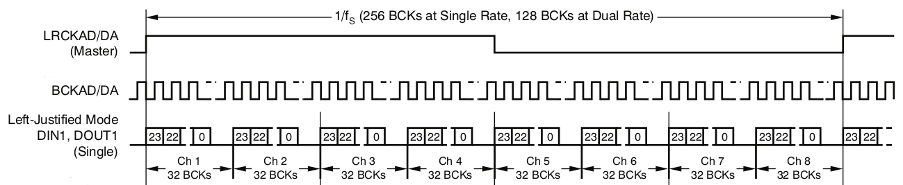
  • As per the PCM3168 datasheet:
    • left justified mode is used
    • dai-tdm-slot-num is set to 8 even though only 4 are actually used
    • dai-tdm-slot-width is set to 32 because the codec takes 24-bit samples but requires 32 clocks per sample (this is solved later in userspace)
    • The codec is master which is usually best regarding clock accuracy, especially since the various SoMs on the market almost never expose the audio clock on the carrier board interface. Here, a crystal was used to clock the PCM3168.

The PCM3168 codec is added under the ecspi3 node as that is where it is connected:

&ecspi3 {
        pcm3168: codec@0 {
                compatible = "ti,pcm3168a";
                reg = <0>;
                spi-max-frequency = <1000000>;
                clocks = <&codec_osc>;
                clock-names = "scki";
                #sound-dai-cells = <1>;
                VDD1-supply = <&reg_module_3v3>;
                VDD2-supply = <&reg_module_3v3>;
                VCCAD1-supply = <&reg_board_5v0>;
                VCCAD2-supply = <&reg_board_5v0>;
                VCCDA1-supply = <&reg_board_5v0>;
                VCCDA2-supply = <&reg_board_5v0>;
        };
};

#sound-dai-cells is what allows to select between the input and output interfaces.

On top of that, multiple issues had to be fixed:

Finally, an ALSA configuration file (/usr/share/alsa/cards/imx7-pcm3168.conf) was written to ensure samples sent to the card are in the proper format, S32_LE. 24-bit samples will simply have zeroes in the least significant byte. For 32-bit samples, the codec will properly ignore the least significant byte.
Also this describes that the first subdevice is the playback (output) device and the second subdevice is the capture (input) device.

imx7-pcm3168.pcm.default {
	@args [ CARD ]
	@args.CARD {
		type string
	}
	type asym
	playback.pcm {
		type plug
		slave {
			pcm {
				type hw
				card $CARD
				device 0
			}
			format S32_LE
			rate 48000
			channels 4
		}
	}
	capture.pcm {
		type plug
		slave {
			pcm {
				type hw
				card $CARD
				device 1
			}
			format S32_LE
			rate 48000
			channels 4
		}
	}
}

On top of that, the dmix and dsnoop ALSA plugins can be used to separate channels.

To conclude, this shows that it is possible to easily leverage existing code to integrate an audio codec in a design by simply writing a device tree snippet and maybe an ALSA configuration file if necessary.

Factory flashing with U-Boot and fastboot on Freescale i.MX6

Introduction

For one of our customers building a product based on i.MX6 with a fairly low-volume, we had to design a mechanism to perform the factory flashing of each product. The goal is to be able to take a freshly produced device from the state of a brick to a state where it has a working embedded Linux system flashed on it. This specific product is using an eMMC as its main storage, and our solution only needs a USB connection with the platform, which makes it a lot simpler than solutions based on network (TFTP, NFS, etc.).

In order to achieve this goal, we have combined the imx-usb-loader tool with the fastboot support in U-Boot and some scripting. Thanks to this combination of a tool, running a single script is sufficient to perform the factory flashing, or even restore an already flashed device back to a known state.

The overall flow of our solution, executed by a shell script, is:

  1. imx-usb-loader pushes over USB a U-Boot bootloader into the i.MX6 RAM, and runs it;
  2. This U-Boot automatically enters fastboot mode;
  3. Using the fastboot protocol and its support in U-Boot, we send and flash each part of the system: partition table, bootloader, bootloader environment and root filesystem (which contains the kernel image).
The SECO uQ7 i.MX6 platform used for our project.

imx-usb-loader

imx-usb-loader is a tool written by Boundary Devices that leverages the Serial Download Procotol (SDP) available in Freescale i.MX5/i.MX6 processors. Implemented in the ROM code of the Freescale SoCs, this protocol allows to send some code over USB or UART to a Freescale processor, even on a platform that has nothing flashed (no bootloader, no operating system). It is therefore a very handy tool to recover i.MX6 platforms, or as an initial step for factory flashing: you can send a U-Boot image over USB and have it run on your platform.

This tool already existed, we only created a package for it in the Buildroot build system, since Buildroot is used for this particular project.

Fastboot

Fastboot is a protocol originally created for Android, which is used primarily to modify the flash filesystem via a USB connection from a host computer. Most Android systems run a bootloader that implements the fastboot protocol, and therefore can be reflashed from a host computer running the corresponding fastboot tool. It sounded like a good candidate for the second step of our factory flashing process, to actually flash the different parts of our system.

Setting up fastboot on the device side

The well known U-Boot bootloader has limited support for this protocol:

The fastboot documentation in U-Boot can be found in the source code, in the doc/README.android-fastboot file. A description of the available fastboot options in U-Boot can be found in this documentation as well as examples. This gives us the device side of the protocol.

In order to make fastboot work in U-Boot, we modified the board configuration file to add the following configuration options:

#define CONFIG_CMD_FASTBOOT
#define CONFIG_USB_FASTBOOT_BUF_ADDR       CONFIG_SYS_LOAD_ADDR
#define CONFIG_USB_FASTBOOT_BUF_SIZE          0x10000000
#define CONFIG_FASTBOOT_FLASH
#define CONFIG_FASTBOOT_FLASH_MMC_DEV    0

Other options have to be selected, depending on the platform to fullfil the fastboot dependencies, such as USB Gadget support, GPT partition support, partitions UUID support or the USB download gadget. They aren’t explicitly defined anywhere, but have to be enabled for the build to succeed.

You can find the patch enabling fastboot on the Seco MX6Q uQ7 here: 0002-secomx6quq7-enable-fastboot.patch.

U-Boot enters the fastboot mode on demand: it has to be explicitly started from the U-Boot command line:

U-Boot> fastboot

From now on, U-Boot waits over USB for the host computer to send fastboot commands.

Using fastboot on the host computer side

Fastboot needs a user-space program on the host computer side to talk to the board. This tool can be found in the Android SDK and is often available through packages in many Linux distributions. However, to make things easier and like we did for imx-usb-loader, we sent a patch to add the Android tools such as fastboot and adb to the Buildroot build system. As of this writing, our patch is still waiting to be applied by the Buildroot maintainers.

Thanks to this, we can use the fastboot tool to list the available fastboot devices connected:

# fastboot devices

Flashing eMMC partitions

For its flashing feature, fastboot identifies the different parts of the system by names. U-Boot maps those names to the name of GPT partitions, so your eMMC normally requires to be partitioned using a GPT partition table and not an old MBR partition table. For example, provided your eMMC has a GPT partition called rootfs, you can do:

# fastboot flash rootfs rootfs.ext4

To reflash the contents of the rootfs partition with the rootfs.ext4 image.

However, while using GPT partitioning is fine in most cases, i.MX6 has a constraint that the bootloader needs to be at a specific location on the eMMC that conflicts with the location of the GPT partition table.

To work around this problem, we patched U-Boot to allow the fastboot flash command to use an absolute offset in the eMMC instead of a partition name. Instead of displaying an error if a partition does not exists, fastboot tries to use the name as an absolute offset. This allowed us to use MBR partitions and to flash at defined offset our images, including U-Boot. For example, to flash U-Boot, we use:

# fastboot flash 0x400 u-boot.imx

The patch adding this work around in U-Boot can be found at 0001-fastboot-allow-to-flash-at-a-given-address.patch. We are working on implementing a better solution that can potentially be accepted upstream.

Automatically starting fastboot

The fastboot command must be explicitly called from the U-Boot prompt in order to enter fastboot mode. This is an issue for our use case, because the flashing process can’t be fully automated and required a human interaction. Using imx-usb-loader, we want to send a U-Boot image that automatically enters fastmode mode.

To achieve this, we modified the U-Boot configuration, to start the fastboot command at boot time:

#define CONFIG_BOOTCOMMAND "fastboot"
#define CONFIG_BOOTDELAY 0

Of course, this configuration is only used for the U-Boot sent using imx-usb-loader. The final U-Boot flashed on the device will not have the same configuration. To distinguish the two images, we named the U-Boot image dedicated to fastboot uboot_DO_NOT_TOUCH.

Putting it all together

We wrote a shell script to automatically launch the modified U-Boot image on the board, and then flash the different images on the eMMC (U-Boot and the root filesystem). We also added an option to flash an MBR partition table as well as flashing a zeroed file to wipe the U-Boot environment. In our project, Buildroot is being used, so our tool makes some assumptions about the location of the tools and image files.

Our script can be found here: flash.sh. To flash the entire system:

# ./flash.sh -a

To flash only certain parts, like the bootloader:

# ./flash.sh -b 

By default, our script expects the Buildroot output directory to be in buildroot/output, but this can be overridden using the BUILDROOT environment variable.

Conclusion

By assembling existing tools and mechanisms, we have been able to quickly create a factory flashing process for i.MX6 platforms that is really simple and efficient. It is worth mentioning that we have re-used the same idea for the factory flashing process of the C.H.I.P computer. On the C.H.I.P, instead of using imx-usb-loader, we have used FEL based booting: the C.H.I.P indeed uses an Allwinner ARM processor, providing a different recovery mechanism than the one available on i.MX6.

Crystalfontz boards support in Yocto

The Yocto 1.5 release is approaching and the Freescale layer trees are now frozen.
Bootlin added support for the various Crystalfontz boards to that release as you can check on the OpenEmbedded metadata index.

Yocto Project

First some preparative work has been done in the meta-fsl-arm layer in order to add the required features to generate an image able to boot on the Crystalfontz boards:

  • Support for a newer version of the Barebox mainline, 2013.08.0. As the previously supported version of Barebox was too old, it didn’t include support for the Crystalfontz boards. Also, some work has been done to make the recipe itself more generic so that custom layers can reuse it more easily.
  • Inclusion of the patches allowing the imx-bootlets to boot Barebox. The imx-bootlets were only able to boot U-Boot or the Linux kernel until now.
  • Creation of a new image type, using the imx-bootlets, then Barebox to boot the Linux kernel. All the boards based on a Freescale mxs SoC (i.mx23 and i.mx28) will benefit of this new image type. This is actually the difficult part where you lay out the compiled binaries (bootloaders, kernel and root filesystem) in the final file that is an SD card image ready to be flashed.

Then, the recipes for the Crystalfontz boards have been added to the meta-fsl-arm-extra layer:

  • First the bootloaders, imx-bootlets and Barebox, including the specific patches and configurations for the Crystalfontz boards.
  • Then the kernel. The linux-cfa recipe uses the 3.10 based kernel available on github.
  • The machine configurations themselves, selecting Barebox as the bootloader and the correct kernel recipe. Also, these are choosing to install the kernel in the root filesystem instead of in its own partition.
  • Touchscreen calibration for the cfa-10057 and the cfa-10058 boards. This is required to get xinput-calibrator working properly as it can’t calibrate without starting values.

In a nut shell, you can now use the following commands to get a working image for your particular Crystalfontz board:

  • For your convenience, Freescale is providing a repo manifest to retrieve all the necessary git repositories. So first download and install repo:
    mkdir ~/bin
    curl https://dl-ssl.google.com/dl/googlesource/git-repo/repo > ~/bin/repo
    chmod a+x ~/bin/repo
    PATH=${PATH}:~/bin
  • We will work in a directory named fsl-community-bsp:
    mkdir fsl-community-bsp
    cd fsl-community-bsp
  • Ask repo to get the master branch, when Yocto 1.5 is released, you could select the new branch. (Edit: starting from September, 28th, you can use the branch named dora)
    repo init -u https://github.com/Freescale/fsl-community-bsp-platform -b master
  • Download the layers:
    repo sync
  • Configure the build for cfa-10036:
    MACHINE=cfa10036 source ./setup-environment build
  • Start the build with:
    bitbake core-image-minimal
  • Grab a cup of coffee!

You’ll end up with an image that you can flash using the following command:
sudo dd if=tmp/deploy/images/cfa10036/core-image-minimal-cfa10036.sdcard of=/dev/mmcblk0

Obviously, you need to replace cfa10036 by the board model you are using in the above commands. While not completely perfect, core-image-sato is also working.

In detail, the contributions from Bootlin are: