It has been more than 7 years since the first draft of a Linux kernel driver for the ARM Primecell PL35X NAND controller was posted on a public mailing list. Maybe because of the lack of time, each new version was delayed so much that it actually needed another iteration just to catch up with the latest internal API changes in the MTD subsystem (quite a number of them happened in the last 2-3 years). The NAND controller itself is part of an ARM Primecell Static Memory bus Controller (SMC) which increased the overall complexity. Finally, the way the commands and data are shared with the memory controller is very specific to the SMC. All these technical points probably played against Xilinx engineers, and Bootlin was contracted in 2021 to finalize the work of getting the ARM Primecell PL35X NAND controller driver in the upstream Linux kernel.
Static Memory Controller principles
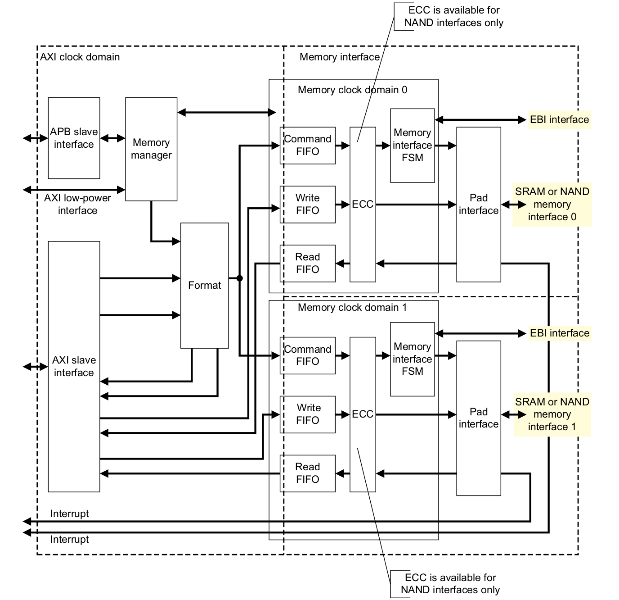
The SMC can interface with two different memory types: NAND or SRAM/NOR. As it features two memory slots, this means that it can drive two memories, but they must be of the same type. When handling NAND devices, a hardware ECC engine is available to perform on-the-fly correction.
As only a single type of memory device can be plugged in at a time (either two SRAM/NORs or two NANDs), we don’t need to share a lot of controls with the SRAM/NOR controllers. So in the end the memory bus driver is almost an empty envelope that relies on the child controller driver to do the job.
Interactions with a memory device
On the CPU side, the controller has two main interfaces: APB and AXI.
The APB interface works like any regular interface: the CPU sees registers that it can access with diverse read and write operations, which will effectively read and write the content of the 32-bit registers located at the desired addresses. This is how the driver configures the device type, the timings, the possible ECC configuration and so forth. All the initial SMC configuration is done through the APB interface.
The AXI interface does not quite work like this. Instead of featuring a set of registers at a fixed address in which the content of the command, address and data cycles would be written in order to be forwarded to the memory device, the AXI interface needs to reserve a notable range in the addressable space. In particular, the offset targetted by the AXI write depend on the type of action that must be performed and the content of the action:
- When requesting the controller to send command and address cycles to the memory device, the datasheet refers to it as the “command phase”.
- When doing I/Os, eg. actually reading from/writing to the memory device, the datasheet calls this the “data phase”.
Both the command and data phase use regular AXI read/writes, but the offsets and values are different than usual.
Command phase
When the driver wants to send command cycles, it must perform one or two register writes. The address of the write operation in the AXI address space must target a specific offset. This offset indicates a number of information:
- A specific bit is set to tell the SMC that it must enter a command phase.
- Part of the offset are made of the shifted values of the different command opcodes for the memory device.
- Part of the offset encodes the number of address cycles to perform on the NAND bus.
The payload of the AXI write contains the value of the address cycles that should be forwarded to the memory device. If there are more than 4 address cycles (which is quite common today), then a second AXI write containing the remaining address cycles as payload must happen at the same offset as before.
/*
 * Define the offset in the AXI address space where to write with:
 * - the bit indicating the command phase
 * - the number of address cycles
 * - the command opcode
 */
cmd_addr = PL35X_SMC_CMD_PHASE |
           PL35X_SMC_CMD_PHASE_NADDRS(naddr_cycles) |
           PL35X_SMC_CMD_PHASE_CMD0(NAND_CMD_XXXX);

/* Define the payload with the address bytes */
for (i = 0, row = 0; row < nrows; i++, row++) {
        [...]
        if (row < 4)
                addr1 |= PL35X_SMC_CMD_PHASE_ADDR(row, addr);
        else
                addr2 |= PL35X_SMC_CMD_PHASE_ADDR(row - 4, addr);
}

/* Send the command and address cycles */
writel(addr1, nfc->io_regs + cmd_addr);
if (naddr_cycles > 4)
        writel(addr2, nfc->io_regs + cmd_addr);
Data phase
The data phase is a bit easier to understand: several AXI reads or writes will be performed at a specific offset. The payload matches our expectations: it is actually the data that we want to read from or write to the device. However, the offset in the AXI address space is again a bit counter-intuitive:
- It contains a specific bit such as the command phase to inform the controller that the data phase must be entered.
- It also contains shifted values of different flags regarding the ECC configuration. The thing is, this offset will change at the end of the I/O operation because the last chunk of data must always be handled differently because of the ECC calculations that must be manually started. We end up reading or writing physically contiguous data by accessing two completely different offsets.
/* I/O transfers: simple case */
for (i = 0; i < buf_end; i++) {
        data_phase_addr = PL35X_SMC_DATA_PHASE;
        if (i + 1 == buf_end)
                data_phase_addr += PL35X_SMC_DATA_PHASE_ECC_LAST;

        writel(buf32[i], nfc->io_regs + data_phase_addr);
}
But what happens if a command cycle must be sent at the end of a data transfer (typical case of a PAGE_WRITE)? While it would certainly be more logical to perform an additional command phase AXI write, it was certainly more optimized to merge data and command phase on the last access. And here is how it looks like:
/* I/O transfers: less straightforward situation */
for (i = 0; i < buf_end; i++) {
        data_phase_addr = PL35X_SMC_DATA_PHASE;
        if (i + 1 == buf_end)
                data_phase_addr +=
                    PL35X_SMC_DATA_PHASE_ECC_LAST |
                    PL35X_SMC_CMD_PHASE_CMD1(NAND_CMD_PAGEPROG) |
                    PL35X_SMC_CMD_PHASE_CMD1_VALID);

        writel(buf32[i], nfc->io_regs + data_phase_addr);
}
Of course, nothing highly unreadable, but at the very least, these accesses are quite uncommon.
A memory bus driver and a NAND controller driver
As explained earlier, this SMC controller can support different types of memories, and this has called for a Device Tree representation where the SMC controller is one node, and the memories connected to it are represented as sub-node. So, the Device Tree representation of the SMC controller, used with its NAND controller looks like this:
    smcc: memory-controller@e000e000 {
      compatible = "arm,pl353-smc-r2p1", "arm,primecell";
      reg = <0xe000e000 0x0001000>;
      clock-names = "memclk", "apb_pclk";
      clocks = <&clkc 11>, <&clkc 44>;
      ranges = <0x0 0x0 0xe1000000 0x1000000 /* Nand CS region */
                0x1 0x0 0xe2000000 0x2000000 /* SRAM/NOR CS0 region */
                0x2 0x0 0xe4000000 0x2000000>; /* SRAM/NOR CS1 region */
      #address-cells = <2>;
      #size-cells = <1>;

      nfc0: nand-controller@0,0 {
        compatible = "arm,pl353-nand-r2p1";
        reg = <0 0 0x1000000>;
        #address-cells = <1>;
        #size-cells = <0>;
      };
    };
So, we first have a node for the SMC controller itself, memory-controller@e000e000, which will allow probing the memory bus driver located at drivers/memory/pl353-smc.c. This driver is very simple: it enables the clocks necessary for the SMC to work, and then it probes the first child device that matches either the cfi-flash or arm,pl353-nand-r2p1 compatible strings. In the latter case (which is illustrated in our example), the NAND controller driver at drivers/mtd/nand/raw/pl35x-nand-controller.c will be probed, and where the two memory areas (accessed through APB and AXI) will be mapped, and accessed to program the NAND controller.
Now in the mainline Linux kernel
Starting from the latest version posted by Xilinx, Miquèl Raynal, Bootlin’s NAND/MTD expert, performed a massive cleanup of the memory bus driver and the NAND controller driver, rewrote entirely the binding file (in YAML schema!) and three versions later, with the support of Xilinx engineers and the acknowledgements of Rob Herring and Krzysztof Kozlowski, managed to finally close the story. The driver is now part of Linux 5.14-rc, and will therefore be in the final Linux 5.14 release in a few weeks!
Thank you for your work. Is this controller used in many devices?
It is at least used in Xilinx Zynq processors. I’m not sure about other SoCs using that, but there could be others as it’s an IP sold by ARM.
Thank you for the quick reply!
I may have one of those processors–it’s on a bitcoin mining controller board.
Actually, this driver is only used for the Zynq 7000 SoCs from Xilinx. The Zynq Ultrascale+ SoCs use the arasan-nand-controller driver.