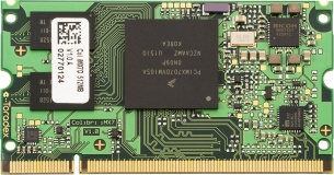
 Bootlin engineer Alexandre Belloni recently worked on a custom carrier board for a Colibri iMX7 system-on-module from Toradex. This system-on-module obviously uses the i.MX7 ARM processor from Freescale/NXP.
While the module includes an SGTL5000 codec, one of the requirements for that project was to handle up to eight audio channels. The SGTL5000 uses I²S and handles only two channels.
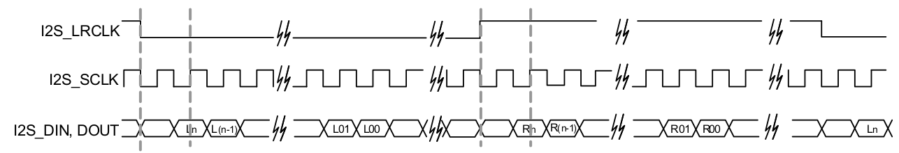
Thankfully, the i.MX7 has multiple audio interfaces and one is fully available on the SODIMM connector of the Colibri iMX7. A TI PCM3168 was chosen for the carrier board and is connected to the second Synchronous Audio Interface (SAI2) of the i.MX7. This codec can handle up to 8 output channels and 6 input channels. It can take multiple formats as its input but TDM takes the smaller number of signals (4 signals: bit clock, word clock, data input and data output).
The current Linux long term support version is 4.9 and was chosen for this project. It has support for both the i.MX7 SAI (sound/soc/fsl/fsl_sai.c) and the PCM3168 (sound/soc/codecs/pcm3168a.c). That’s two of the three components that are needed, the last one being the driver linking both by describing the topology of the “sound card”. In order to keep the custom code to the minimum, there is an existing generic driver called simple-card (sound/soc/generic/simple-card.c). It is always worth trying to use it unless something really specific prevents that. Using it was as simple as writing the following DT node:
        board_sound {
                compatible = "simple-audio-card";
                simple-audio-card,name = "imx7-pcm3168";
                simple-audio-card,widgets =
                        "Speaker", "Channel1out",
                        "Speaker", "Channel2out",
                        "Speaker", "Channel3out",
                        "Speaker", "Channel4out",
                        "Microphone", "Channel1in",
                        "Microphone", "Channel2in",
                        "Microphone", "Channel3in",
                        "Microphone", "Channel4in";
                simple-audio-card,routing =
                        "Channel1out", "AOUT1L",
                        "Channel2out", "AOUT1R",
                        "Channel3out", "AOUT2L",
                        "Channel4out", "AOUT2R",
                        "Channel1in", "AIN1L",
                        "Channel2in", "AIN1R",
                        "Channel3in", "AIN2L",
                        "Channel4in", "AIN2R";

                simple-audio-card,dai-link@0 {
                        format = "left_j";
                        bitclock-master = <&pcm3168_dac>;
                        frame-master = <&pcm3168_dac>;
                        frame-inversion;

                        cpu {
                                sound-dai = <&sai2>;
                                dai-tdm-slot-num = <8>;
                                dai-tdm-slot-width = <32>;
                        };

                        pcm3168_dac: codec {
                                sound-dai = <&pcm3168 0>;
                                clocks = <&codec_osc>;
                        };
                };

                simple-audio-card,dai-link@2 {
                        format = "left_j";
                        bitclock-master = <&pcm3168_adc>;
                        frame-master = <&pcm3168_adc>;

                        cpu {
                                sound-dai = <&sai2>;
                                dai-tdm-slot-num = <8>;
                                dai-tdm-slot-width = <32>;
                        };

                        pcm3168_adc: codec {
                                sound-dai = <&pcm3168 1>;
                                clocks = <&codec_osc>;
                        };
                };
        };
There are multiple things of interest:
- Only 4 input channels and 4 output channels are routed because the carrier board only had that wired.
- There are two DAI links because the pcm3168 driver exposes inputs and outputs separately
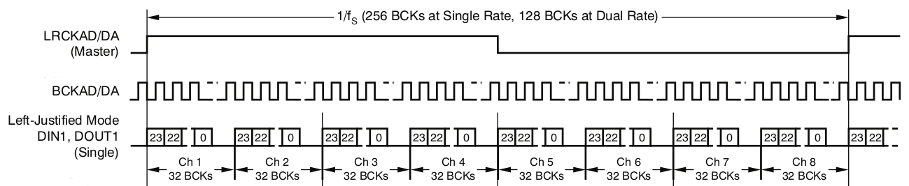
- As per the PCM3168 datasheet:
- left justified mode is used
-
dai-tdm-slot-numis set to 8 even though only 4 are actually used -
dai-tdm-slot-widthis set to 32 because the codec takes 24-bit samples but requires 32 clocks per sample (this is solved later in userspace) - The codec is master which is usually best regarding clock accuracy, especially since the various SoMs on the market almost never expose the audio clock on the carrier board interface. Here, a crystal was used to clock the PCM3168.
The PCM3168 codec is added under the ecspi3 node as that is where it is connected:
&ecspi3 {
pcm3168: codec@0 {
compatible = "ti,pcm3168a";
reg = <0>;
spi-max-frequency = <1000000>;
clocks = <&codec_osc>;
clock-names = "scki";
#sound-dai-cells = <1>;
VDD1-supply = <®_module_3v3>;
VDD2-supply = <®_module_3v3>;
VCCAD1-supply = <®_board_5v0>;
VCCAD2-supply = <®_board_5v0>;
VCCDA1-supply = <®_board_5v0>;
VCCDA2-supply = <®_board_5v0>;
};
};
#sound-dai-cells is what allows to select between the input and output interfaces.
On top of that, multiple issues had to be fixed:
- a small patch was added to
fsl_sai.cto make it accept more than 2 channels. It is now upstream:
https://git.kernel.org/pub/scm/linux/kernel/git/torvalds/linux.git/commit/?id=4957b556f5e7ef9855d698b7ae2f0d4245c7ff50 -
pcm3168a_hw_params()is only handling two channels in its calculations. This was solved by hardcoding a few values so nothing has been sent upstream yet. - There was an issue where the DMA would not order the samples correctly. It could not be heard using the usual 440Hz tone, but ramping down a sine shows it quite clearly:

This took most of the development effort and was solved in 4.10:
https://git.kernel.org/pub/scm/linux/kernel/git/torvalds/linux.git/commit/?id=85f57752b33cf12f1d583f0c10b752292de00abe
Finally, an ALSA configuration file (/usr/share/alsa/cards/imx7-pcm3168.conf) was written to ensure samples sent to the card are in the proper format, S32_LE. 24-bit samples will simply have zeroes in the least significant byte. For 32-bit samples, the codec will properly ignore the least significant byte.
Also this describes that the first subdevice is the playback (output) device and the second subdevice is the capture (input) device.
imx7-pcm3168.pcm.default {
	@args [ CARD ]
	@args.CARD {
		type string
	}
	type asym
	playback.pcm {
		type plug
		slave {
			pcm {
				type hw
				card $CARD
				device 0
			}
			format S32_LE
			rate 48000
			channels 4
		}
	}
	capture.pcm {
		type plug
		slave {
			pcm {
				type hw
				card $CARD
				device 1
			}
			format S32_LE
			rate 48000
			channels 4
		}
	}
}
On top of that, the dmix and dsnoop ALSA plugins can be used to separate channels.
To conclude, this shows that it is possible to easily leverage existing code to integrate an audio codec in a design by simply writing a device tree snippet and maybe an ALSA configuration file if necessary.
Dear Alexandre,
Thanks for share your valuable experience on this topic.
please put a schematic connection between codec and iMX7 so the Hardware layer become as clear as the software.
Dear Alexandre,
Thanks for the wonderfull explanation and I will like to also test this on my own. Can you supply a schematic please?
Unfortunately, I can’t provide schematics. However, there is really not much to it. I that case, the pcm3168 to imx7 connections where the following: LRCKAD to SAI2_RX_SYNC, BCKAD to SAI2_RX_BCLK, DOUT1 to SAI2_RX_DATA0, LRCKDA to SAI2_TX_SYNC, BCKDA to SAI2_TX_BCLK, DIN1 to SAI2_TX_DATA0. The other connection was SPI to control the codec, as shown in the blog post.
Hello Alexandre,
I am working on similar kind of setup with iMX8M mini board with 4 channel audio interface.
I did the single stereo channel interface with iMX8M board successfully, but not understanding TDM interface flow. How we can we record the TDM audio stream to iMX8M board.
e.g. for single channel i used
arecord -f S16_LE -c2 -r48000 -D hw:1,0 fileName
And also how to separate those audio channels from TDM audio stream.
Any reference/ guidance will help.
Thank you.!
You have a number of solutions to capture channel 2 and 3, the most readily available is probably using alsalib. This is described in our blog post about audio routing and muxing, this should point you in the right direction.
Hi Malay,
I’m working too with the IMX8MM EVK connected with J1001 connector to a custom board with PCM3168 codec. Can you send me your device tree configuration?
Thanks in advance.
Hello Alexandre,
thank you for your guidance.
Can you upload your &sai2 node details for the above configuration, so that i can take some reference from that.
Well, the is not much to that node, it mainly reuses what is provided by the SoC dtsi:
&iomuxc { pinctrl_sai2: sai2-grp { fsl,pins = < MX7D_PAD_SAI2_TX_BCLK__SAI2_TX_BCLK 0x1f MX7D_PAD_SAI2_TX_SYNC__SAI2_TX_SYNC 0x1f MX7D_PAD_SD2_DATA3__SAI2_TX_DATA0 0x30 MX7D_PAD_SD2_DATA0__SAI2_RX_DATA0 0x1f MX7D_PAD_SAI1_RX_BCLK__SAI2_RX_BCLK 0x1f MX7D_PAD_SAI1_RX_SYNC__SAI2_RX_SYNC 0x1f >; }; }; &sai2 { pinctrl-names = "default"; pinctrl-0 = <&pinctrl_sai2>; status = "okay"; fsl,sai-asynchronous; };Hello Alexandre,
Very good article.
I’m starting a new project, in which this article can help me, but I have some doubts.
What I intend to develop is a central equipment “A” (with the micro imx8m Mini and the codec pcm3168A) and I want to connect 6 audios from 6 different audio devices “B” (which only contain an analog microphone and a loudspeaker).
From each audio device I want to be able to communicate (through A) via SIP with a central (telephone) independently.
I imagine that is possible, no?
With the IMX8mm, can I have 6 different’s audio interfaces and configure a SIP account for each one and make different calls to each one of them?
Thanks
Ricardo
Hello Ricardo,
You should have a look at our other article where you will learn how to split channels in multiple stereo streams using alsalib. Note that you can also acheive that using pulseaudio or pipewire and that will be more flexible.