 Among all activities I’ve been doing at Bootlin during the past few months, one has been to add support for the Maxim MAX7360 Key-Switch Controller and LED Driver/GPIOs chip to the Linux kernel. Together with my colleague Kamel Bouhara, we developed Linux kernel device drivers to support it and upstreamed them to the mainline kernel. The full set of drivers have been merged in the upstream Linux kernel, and will be available in the upcoming Linux 6.18 release.
In this blog post, we will share some details on how this hardware works, and how it is now supported by the Linux kernel.
The MAX7360 HW capabilities
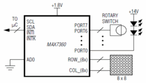
The MAX7360’s primary function is to support a matrix keypad. With 8 rows and 8 columns, it can handle up to 64 keys.
Beyond keypad support, the chip provides 8 additional PORT pins. These PORT pins can be used either as GPIOs with constant current mode and interrupt capabilities, or as PWM outputs. This capability allows the pins to serve as additional inputs or to drive LEDs on the keypad.
But what if you have a smaller keypad that doesn’t require to drive 64 keys? The chip does provide some flexibility: on the 8 columns provided by the chip, 6 can be repurposed as output-only GPIO, or in other words GPOs.
Do you want more? Two of the GPIOs can actually be used to support a rotary encoder.
Its datasheet gives a nice block diagram of the HW capabilities:
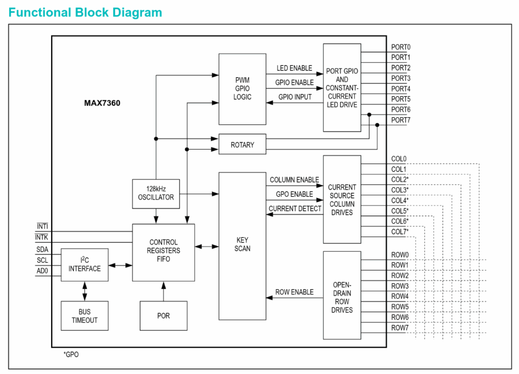
Overall, this makes the MAX7360 a chip offering a large numbering of features, which we wanted to all support in Linux.
The overall implementation architecture
This chip packs quite a lot of functionality that needs to be integrated across several Linux kernel subsystems: input, GPIO, IRQ, and PWM. Of course, this is too much for a single monolithic device driver. Instead, we split device support into one component per feature, all organized under a multifunction device (MFD). If you’re not familiar with MFD, you may want to review the slides from Bootlin engineer’s Alexandre Belloni Supporting multi-function devices in the Linux kernel:
a tour of the mfd, regmap and syscon APIs.
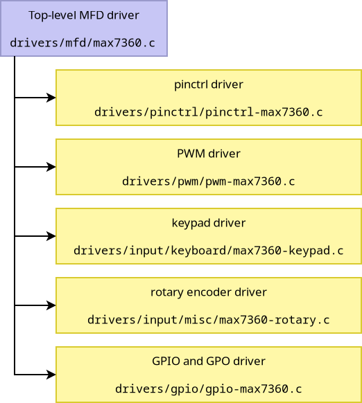
Our MFD driver located at drivers/mfd/max7360.c is quite simple: it handles basic device initialization (device reset and IRQ masking) and registers all MFD cells (sub-devices).
The diagram below shows the overall software architecture in Linux, with the top-level MFD driver, and all sub-drivers, each handling one feature of the MAX7360:
The pinctrl implementation
Pin muxing isn’t one of the features we listed above in the device description, and at first we tried to implement MAX7360 support without involving the pinctrl subsystem. However, upon reflection, this device does indeed support pin muxing: keypad columns can double as GPOs, and GPIOs can serve as PWM outputs or rotary encoder controllers!
After some discussion on the mailing list, we decided to implement a pinctrl driver to control this pin muxing capability. Our implementation is quite basic, supporting only 9 pin groups: 8 dedicated to individual pins (with either GPIO or PWM functionality) and a ninth group grouping pins 6 and 7 together for rotary encoder functionality.
You might be wondering about the keypad columns that can be used as GPOs: this is also a form of pin muxing capability. However, unlike the pins mentioned above, these cannot be controlled independently. Pin functionality is partitioned: the first N pins serve as columns while the remaining ones function as GPOs. Consequently, we decided to delegate management of this feature to the respective keypad and GPIO drivers.
Overall, you can find our pinctrl driver at drivers/pinctrl/pinctrl-max7360.c.
The keyboard input driver
As stated previously, the keypad matrix is the chip’s primary feature. By reusing existing kernel components designed for generic matrix keypads, the driver loads row and column configuration from the Device Tree, along with the keypad keymap. An interrupt handler monitors key presses and reports them to the input subsystem.
On a running system, it exposes an input device that generates keyboard events according to the configured keymap.
You can find this keypad matrix driver at drivers/input/keyboard/max7360-keypad.c.
Rotary encoder input driver
For this functionality, we aimed to closely mimic the behavior of the existing rotary_encoder driver. This driver exposes an input device that generates either relative or absolute events on an axis specified in the Device Tree.
- Relative events can be used for devices such as a mouse wheel.
- Absolute events can be used to implement controls with a range of values, such as a volume knob. In such situation, minimal and maximal values are also found from the device tree.
The implementation is quite straightforward: it consists of an initialization function that retrieves configuration information from the Device Tree, and an interrupt handler that reports events to the input subsystem.
Check out the driver code at drivers/input/misc/max7360-rotary.c.
PWM support
On the PWM side, the MAX7360 has some limitations: all 8 PWM outputs have a fixed period of 2 ms and offer no polarity control. However, this is perfectly adequate for dimming LEDs.
To make the best use of the PWM subsystem, our driver leverages the new PWM waveform abstraction, which decouples hardware settings computation from the code that applies the changes.
The driver code is in drivers/pwm/pwm-max7360.c.
GPIO support
For GPIO capabilities, we expose two separate GPIO banks: one for the dedicated GPIOs provided by the chipset and another for keypad columns that can be repurposed as GPOs. In the next two sections, we’ll separately discuss those two banks, as supporting each came with its own challenges.
Check out the full driver code at drivers/gpio/gpio-max7360.c.
The GPIO bank
Configuring the first bank is relatively simple: the pinctrl driver allows assignment of the corresponding pins to either GPIO or other functions, and the GPIO driver handles them like any standard GPIO. However, there were two unique aspects that required enhancements to the GPIO subsystem.
First, since we handle all device communication through regmap, we use both regmap-irq and gpio-regmap to manage these. However, these interfaces abstract the underlying irq_chip and gpio_chip structures, leaving no direct way to register a regmap-based GPIO bank with interrupt support. This was improved by adding fields to the gpio_regmap structure, allowing to describe the IRQ configuration.
The second challenge comes from another MAX7360 limitation: while it supports interrupts on these GPIOs, there’s no register indicating which GPIO triggered the interrupt. We only know that an interrupt occurred. The common solution is to emulate interrupts for each line by monitoring their levels: on each interrupt, we compare the current level with the previously known state, and if it changed, we simulate an interrupt. Of course this can result in missed interrupts if the MAX7360 interrupt handler executes too late and the GPIO line switches back to its original value, but for sufficiently slow signals, this is a reasonable and likely the only viable approach. Since this is a common situation requiring the same implementation across multiple drivers, we decided to improve gpio-regmap to support this behavior with a flag variable.
The GPO bank
The second bank is different: being output-only, it has no interrupt support. Remember that we don’t use the pinctrl driver to configure which pins serve as keypad columns versus GPOs? This must be handled here. The solution we adopted is actually quite simple: to maintain stable GPIO numbers, the driver always creates a bank of 8 GPIOs but marks some as unusable, based on the number of columns used by the keypad. GPIOs can be marked as unusable using the gpiolib valid_mask field, but there was one final catch: no mechanism existed to initialize this field correctly when using gpio-regmap. A final improvement to gpio-regmap added support for specifying an initialization callback to populate the underlying gpio_chip structure.
What about the Device Tree bindings?
For Device Tree support, the MAX7360 uses two bindings:
- The first describes the MAX7360 I²C device with its associated properties:
- Keypad row and column counts, along with the keymap
- Axis and mode (absolute or relative) for the rotary encoder
- Debounce delays for both keypad and rotary encoder functionality
- Pinctrl configuration
- The second covers the GPIO banks, which appear as child nodes of the above node.
Here is a Device Tree sample using both of these bindings:
i2c {
  #address-cells = <1>;
  #size-cells = <0>;

  io-expander@38 {
    compatible = "maxim,max7360";
    reg = <0x38>;

    interrupt-parent = <&gpio1>;
    interrupts = <23 IRQ_TYPE_LEVEL_LOW>,
                 <24 IRQ_TYPE_LEVEL_LOW>;
    interrupt-names = "inti", "intk";

    /* Here we have a keypad matrix of 8 rows, 4 columns.
     * The 4 remaining column lines will be exposed as output-only GPIOs.
     * Three keys are present on the keypad:
     *   - F5 on row 0, column 0.
     *   - F4 on row 1, column 0.
     *   - F6 on row 2, column 1.
     */
    keypad,num-rows = <8>;
    keypad,num-columns = <4>;
    linux,keymap = <
      MATRIX_KEY(0x00, 0x00, KEY_F5)
      MATRIX_KEY(0x01, 0x00, KEY_F4)
      MATRIX_KEY(0x02, 0x01, KEY_F6)
      >;
    keypad-debounce-delay-ms = <10>;

    /* The rotary encoder generate relative events, on axis REL_X (0).
     */
    rotary-debounce-delay-ms = <2>;
    linux,axis = <0>; /* REL_X */
    rotary-encoder,relative-axis;

    #pwm-cells = <3>;

    /* The first GPIO bank: with interrupts.
     */
    max7360_gpio: gpio {
      compatible = "maxim,max7360-gpio";

      gpio-controller;
      #gpio-cells = <2>;

      interrupt-controller;
      #interrupt-cells = <0x2>;
    };

    /* The second GPIO bank: output-only.
     */
    max7360_gpo: gpo {
      compatible = "maxim,max7360-gpo";

      gpio-controller;
      #gpio-cells = <2>;
    };

    /* The pinctrl configuration of one pin:
     * PORT2 pin is used with the PWM function.
     */
    backlight_pins: backlight-pins {
      pins = "PORT2";
      function = "pwm";
    };
  };
};
Conclusion
Adding MAX7360 support represents my largest Linux kernel contribution to date and has been a truly instructive journey. It introduced me to helper frameworks such as regmap-irq, gpio-regmap and the PWM waveform callback, which I wasn’t previously familiar with. I have to thank all reviewers for the help they provided on the mailing list in order to improve the quality of this set of drivers.