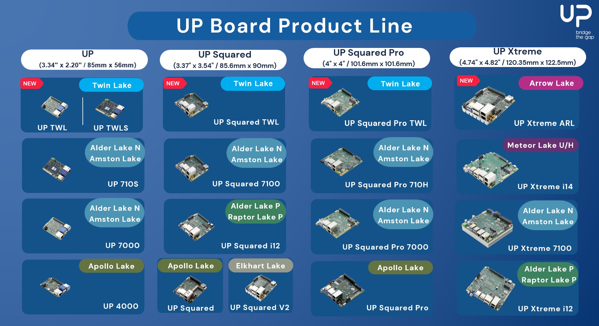
 The UP Board family of platforms, developed by AAEON, is a series of compact, high-performance single-board computers (SBCs) widely used in the industry and embedded applications. They combine high-performance Intel processors with versatile I/O through a 40-pin Raspberry Pi-like header. At its core, an FPGA manages pin functionality, routing, and direction, enabling flexible use as I2C, UART, or GPIO. Supporting this setup in Linux is uniquely challenging and fascinating, and we were recently involved in bringing support for these I/Os upstream, successfully closing a story that had been open for seven years!
The hardware
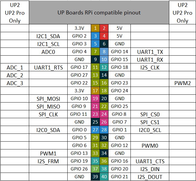
The 40-pin Raspberry Pi-like header available on UP Board platforms offers a set of configurable pins supporting various functions:
This header is connected to the SoC through an FPGA, which serves two key roles: it acts as a level shifter to ensure signal compatibility and as a pin controller. This allows each pin to be assigned to a specific mode, such as I2C, UART and so on, or configured as a GPIO, providing flexibility for different use cases. The following diagram illustrates this principle:
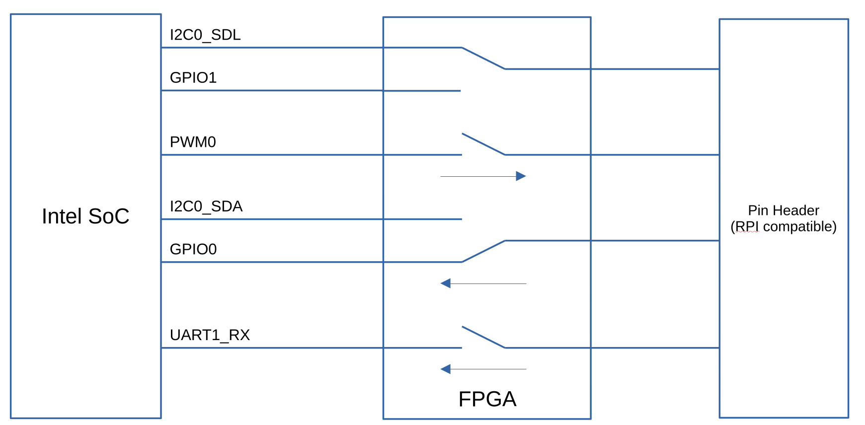
The FPGA manages pin routing and signal control as follows:
- Multiplexed pins (e.g., I2C0_SDL, GPIO1): The FPGA acts as a multiplexer, forwarding the correct signal to the pin header based on the selected mode.
- Switchable pins (e.g., UART1_RX): The FPGA acts as a switch, either forwarding the SoC pin to the header or setting it to high-impedance (HIGH-Z). If the user requests GPIO mode for such a pin, the FPGA must instruct the SoC to reconfigure its pin accordingly.
- Pin Direction Management: For all pins except I2C, the FPGA requires knowledge of the pin direction to configure its internal circuitry. Therefore, SoC pin states must be synchronized with FPGA configuration.
The FPGA provides a pin controller and a GPIO chip, but at the same time it is itself a pin and GPIO consumer which is not a common use case. Additionally it also provides LEDs. All these aspects make supporting this in Linux non-trivial.
Previous effort
To support these I/Os, AAEON has been providing for quite some an out-of-tree Linux kernel driver, which can be built using DKMS. However, AAEON wanted to improve the experience for their users, by having native support for this pin configuration chip in the upstream Linux kernel. Two major attempts had already been made to try to upstream support for this:
- First Attempt (2018), three iterations of a patch series were submitted:
- Second Attempt (2022–2023), eight iterations of another patch series were submitted:
The main critique on those series centered on the pinctrl driver’s design, which relies on Intel-specific pinctrl code rather than the generic API. Intel pinctrl macros are tailored for Intel SoCs, making the current approach unsuitable for upstream inclusion. Additionally, the drivers did not fully follow best practices.
More recently, AAEON asked us at Bootlin to take over this work and push it to completion, by getting a solution accepted upstream.
Driver Rework and Upstream Progress
Following maintainers’ feedback, the drivers underwent a significant rewrite. The most notable change was in the pinctrl driver: all Intel-specific code was removed, and the driver now uses the standard in-kernel GPIO API (gpiolib) to manage Intel SoC pins. We reworked the code accordingly, and sent a first series in December 2024. This series included 5 patches:
- A patch adding a MFD (Multi-Function Driver), which binds based on ACPI identifiers, and instantiates the LED and pinctrl devices
- A patch adding an LED driver
- A patch adding a new gpiolib API that was needed for our use-case
- A patch adding the pinctrl driver
- A patch adding relevant entries in the MAINTAINERS file
The MFD driver and LED driver themselves didn’t raise much discussions, and were promptly merged and became part of Linux 6.14 after just one review cycle, with the following commits:
- mfd: Add support for AAEON UP board FPGA
- leds: Add AAEON UP board LED driver
- MAINTAINERS: Add entry for AAEON UP board FPGA drivers
However, the pinctrl driver naturally caused more discussions, with two main issues raised by the maintainers:
- The pinctrl driver exposes a virtual gpiochip to userspace, which internally drives GPIOs from an other gpiochip. This use case is already supported in the Linux kernel by the gpio-aggregator driver. Maintainers suggested to extend the gpio-aggregator driver to create a reusable library. If you are not familiar with this driver we suggest looking at a previous blog post from Bootlin engineer Hervé Codina on this topic.
- The driver does not consume SoC pins. While a pinctrl proxy was proposed, testing and discussion revealed it to be overly complex for this niche use case. The chosen solution was to use pinctrl mapping instead.
We therefore reworked our proposal to take into account this feedback, and iterated with the community through 8 additional iterations:
- version 2, March 17, 2025
- version 3, April 16, 2025
- version 4, April 29, 2025
- version 5, May 6, 2025
- version 6, May 20, 2025
- version 7, June 9, 2025
- version 8, June 11, 2025
- version 9, August 11, 2025
After nine iterations, both the new GPIO forwarder library and the pinctrl driver were accepted and merged into the Linux 6.18 release. The GPIO forwarder library is now integrated as part of the gpio-aggregator driver. There is no change in the gpio-aggregator behavior, but now gpio-aggregator driver uses this new library. It is now also possible to add and remove GPIO descriptors at runtime. For details, see the individual commits:
- pinctrl: Add pin controller driver for AAEON UP boards
- lib/string_choices: Add str_input_output() helper
- gpio: aggregator: add possibility to attach data to the forwarder
- gpio: aggregator: handle runtime registration of gpio_desc in gpiochip_fwd
- gpio: aggregator: export symbols of the GPIO forwarder library
- gpio: aggregator: update gpiochip_fwd_setup_delay_line() parameters
- gpio: aggregator: refactor the forwarder registration part
- gpio: aggregator: refactor the code to add GPIO desc in the forwarder
- gpio: aggregator: move GPIO forwarder allocation in a dedicated function
- gpiolib: add support to register sparse pin range
GPIO forwarder library
The key new element that we contributed and that enabled support for the AAEON use-case is the GPIO forwarder library, which therefore deserves additional explanations. This library is part of the gpio-aggregator driver and enables kernel drivers to create virtual gpiochips, grouping multiple GPIOs.
Prerequisites
In order to use this GPIO forwarder library in a kernel driver, one first needs to:
- Enable GPIO Aggregator support in your kernel configuration:
CONFIG_GPIO_AGGREGATOR=y - Include the GPIO forwarder header in your driver:
#include <linux/gpio/forwarder.h> - Import the GPIO forwarder symbol namespace:
MODULE_IMPORT_NS("GPIO_FORWARDER")
API
Then, the driver can use the API offered by this library, which provides the following features:
- Allocate and initialize a GPIO Forwarder using the
devm_gpiochip_fwd_alloc()function - Add GPIO descriptors using the
gpiochip_fwd_desc_add()function - Register the GPIO forwarder to make the virtual gpiochip avaialble in userspace, using
gpiochip_fwd_register() - If needed, one can remove GPIO descriptors at runtime, using
gpiochip_fwd_desc_free() - For advanced use cases, you may need to override the default GPIO operations provided by the forwarder. The symbols of the gpiochip forwarder operations are exported and can be used in custom operations:
gpiochip_fwd_gpio_request,gpiochip_fwd_gpio_get_direction,gpiochip_fwd_gpio_direction_input,gpiochip_fwd_gpio_direction_output,gpiochip_fwd_gpio_get,gpiochip_fwd_gpio_get_multiple,gpiochip_fwd_gpio_set,gpiochip_fwd_gpio_set_multiple,gpiochip_fwd_gpio_set_config,gpiochip_fwd_gpio_to_irq
UP Board pinctrl driver: customizing GPIO forwarder operations
Now that we have presented the high-level API of the GPIO forwarder, we can discuss how it has been used for the specific case of the UP Board pinctrl driver. In particular, this driver must coordinate Intel SoC pins with the FPGA’s internal circuitry. To achieve this, certain GPIO operations require custom logic, so our UP Board pinctrl driver overrides some default operations:
chip = gpiochip_fwd_get_gpiochip(fwd);
chip->request = upboard_gpio_request;
chip->free = upboard_gpio_free;
chip->get_direction = upboard_gpio_get_direction;
chip->direction_output = upboard_gpio_direction_output;
chip->direction_input = upboard_gpio_direction_input;
A first example is the ->request() operation, which needs to be overridden. Indeed, on the UP Boards, pins are by default used in function mode, so no GPIO descriptors are added in the forwarder during the probe. However, when a pin is requested as a GPIO, we must request the correct GPIO descriptor and add it to the forwarder using gpiochip_fwd_desc_add():
static int upboard_gpio_request(struct gpio_chip *gc, unsigned int offset)
{
	struct gpiochip_fwd *fwd = gpiochip_get_data(gc);
	struct upboard_pinctrl *pctrl = gpiochip_fwd_get_data(fwd);
	unsigned int pin = pctrl->pctrl_data->pin_header[offset];
	struct gpio_desc *desc;
	int ret;

	ret = pinctrl_gpio_request(gc, offset);
	if (ret)
		return ret;

	desc = gpiod_get_index(pctrl->dev, "external", pin, 0);
	if (IS_ERR(desc)) {
		pinctrl_gpio_free(gc, offset);
		return PTR_ERR(desc);
	}

	return gpiochip_fwd_desc_add(fwd, desc, offset);
}
Another example is the ->direction_input() operation, it is overriden because the FPGA must be notified that the pin will be used as input (using pinctrl_gpio_direction_input()), before calling the default direction_input operation of the forwarder using gpiochip_fwd_gpio_direction_input():
static int upboard_gpio_direction_input(struct gpio_chip *gc, unsigned int offset)
{
	struct gpiochip_fwd *fwd = gpiochip_get_data(gc);
	int ret;

	ret = pinctrl_gpio_direction_input(gc, offset);
	if (ret)
		return ret;

	return gpiochip_fwd_gpio_direction_input(fwd, offset);
}
Pinctrl mappings
As discussed previously, another issue raised by the kernel maintainers on the initial proposal was that the driver did not consume the pins from the SoC. The solution to this was to implement pinctrl mappings. These mappings, hardcoded in the driver, contains the pin group to request, the function to select and the name of the device controlling this specific mapping. They look like this:
static const struct pinctrl_map pinctrl_map_apl01[] = {
        PIN_MAP_MUX_GROUP_DEFAULT("upboard-pinctrl",
                                 "INT3452:00",
                                 "pwm0_grp", "pwm0"),
        PIN_MAP_MUX_GROUP_DEFAULT("upboard-pinctrl",
                                 "INT3452:00",
                                 "pwm1_grp", "pwm1"),
        PIN_MAP_MUX_GROUP_DEFAULT("upboard-pinctrl",
                                 "INT3452:00",
                                 "uart1_grp", "uart1"),
        PIN_MAP_MUX_GROUP_DEFAULT("upboard-pinctrl",
                                 "INT3452:02",
                                 "i2c0_grp", "i2c0"),
        PIN_MAP_MUX_GROUP_DEFAULT("upboard-pinctrl",
                                 "INT3452:02",
                                 "i2c1_grp", "i2c1"),
        PIN_MAP_MUX_GROUP_DEFAULT("upboard-pinctrl",
                                 "INT3452:01",
                                 "ssp0_grp", "ssp0"),
};
Each board uses a custom set of pinctrl mappings, tailored to its specific hardware configuration. The DMI table is used to match the board model and apply the correct mappings. For now the driver only supports the UP Squared board, but support for additional boards of the UP family can easily be added:
static const struct dmi_system_id dmi_platform_info[] = {
        {
                /* UP Squared */
                .matches = {
                        DMI_EXACT_MATCH(DMI_SYS_VENDOR, "AAEON"),
                        DMI_EXACT_MATCH(DMI_BOARD_NAME, "UP-APL01"),
                },
                .driver_data = (void *)&upboard_pinctrl_map_apl01,
        },
        { }
};
During the probe, the pinctrl driver registers the mappings using devm_pinctrl_register_mappings(), and applies them:
pinctrl = devm_pinctrl_get_select_default(dev);
if (IS_ERR(pinctrl))
	return dev_err_probe(dev, PTR_ERR(pinctrl),
                             "Failed to select pinctrl\n");

ret = pinctrl_enable(pctrl->pctldev);
if (ret)
	return ret;
Going further
While the MFD and LED drivers already support most boards in the UP family, the pinctrl driver currently only supports the UP Squared board. The next phase is to expand pinctrl support by adding mappings for other UP family boards. This effort may also require updates to the Intel pinctrl drivers to include any missing pin groups or functions. Feel free to test and contribute!