 Recently, one of our customers designing an embedded Linux system with specific audio needs had a use case where they had a sound card with more than one audio channel, and they needed to separate individual channels so that they can be used by different applications. This is a fairly common use case, we would like to share in this blog post how we achieved this, for both input and output audio channels.
The most common use case would be separating a 4 or 8-channel sound card in multiple stereo PCM devices. For this, alsa-lib, the userspace API interface to the ALSA drivers, provides PCM plugins. Those plugins are configured through configuration files that are usually known to be /etc/asound.conf or $(HOME)/.asoundrc. However, through the configuration of /usr/share/alsa/alsa.conf, it is also possible, and in fact recommended to use a card-specific configuration, named /usr/share/alsa/cards/<card_name>.conf.
The syntax of this configuration is documented in the alsa-lib configuration documentation, and the most interesting part of the documentation for our purpose is the pcm plugin documentation.
Audio inputs
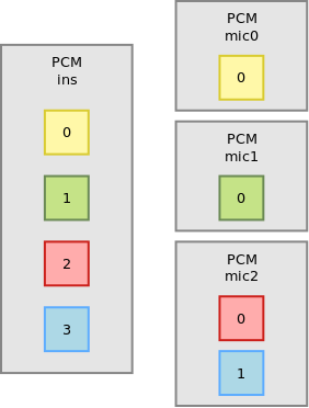
For example, let’s say we have a 4-channel input sound card, which we want to split in 2 mono inputs and one stereo input, as follows:

In the ALSA configuration file, we start by defining the input pcm:
pcm_slave.ins {
	pcm "hw:0,1"
	rate 44100
	channels 4
}
pcm "hw:0,1" refers to the the second subdevice of the first sound card present in the system. In our case, this is the capture device. rate and channels specify the parameters of the stream we want to set up for the device. It is not strictly necessary but this allows to enable automatic sample rate or size conversion if this is desired.
Then we can split the inputs:
pcm.mic0 {
	type dsnoop
	ipc_key 12342
	slave ins
	bindings.0 0
}

pcm.mic1 {
	type plug
	slave.pcm {
		type dsnoop
		ipc_key 12342
		slave ins
		bindings.0 1
	}
}

pcm.mic2 {
	type dsnoop
	ipc_key 12342
	slave ins
	bindings.0 2
	bindings.1 3
}
mic0 is of type dsnoop, this is the plugin splitting capture PCMs. The ipc_key is an integer that has to be unique: it is used internally to share buffers. slave indicates the underlying PCM that will be split, it refers to the PCM device we have defined before, with the name ins. Finally, bindings is an array mapping the PCM channels to its slave channels. This is why mic0 and mic1, which are mono inputs, both only use bindings.0, while mic2 being stereo has both bindings.0 and bindings.1. Overall, mic0 will have channel 0 of our input PCM, mic1 will have channel 1 of our input PCM, and mic2 will have channels 2 and 3 of our input PCM.
The final interesting thing in this example is the difference between mic0 and mic1. While mic0 and mic2 will not do any conversion on their stream and pass it as is to the slave pcm, mic1 is using the automatic conversion plugin, plug. So whatever type of stream will be requested by the application, what is provided by the sound card will be converted to the correct format and rate. This conversion is done in software and so runs on the CPU, which is usually something that should be avoided on an embedded system.
Also, note that the channel splitting happens at the dsnoop level. Doing it at an upper level would mean that the 4 channels would be copied before being split. For example the following configuration would be a mistake:
pcm.dsnoop {
    type dsnoop
    ipc_key 512
    slave {
        pcm "hw:0,0"
        rate 44100
    }
}

pcm.mic0 {
    type plug
    slave dsnoop
    ttable.0.0 1
}

pcm.mic1 {
    type plug
    slave dsnoop
    ttable.0.1 1
}
Audio outputs
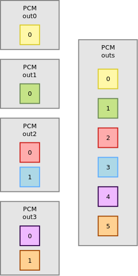
For this example, let’s say we have a 6-channel output that we want to split in 2 mono outputs and 2 stereo outputs:

As before, let’s define the slave PCM for convenience:
pcm_slave.outs {
	pcm "hw:0,0"
	rate 44100
	channels 6
}
Now, for the split:
pcm.out0 {
	type dshare
	ipc_key 4242
	slave outs
	bindings.0 0
}

pcm.out1 {
	type plug
	slave.pcm {
		type dshare
		ipc_key 4242
		slave outs
		bindings.0 1
	}
}

pcm.out2 {
	type dshare
	ipc_key 4242
	slave outs
	bindings.0 2
	bindings.1 3
}

pcm.out3 {
	type dmix
	ipc_key 4242
	slave outs
	bindings.0 4
	bindings.1 5
}
out0 is of type dshare. While usually dmix is presented as the reverse of dsnoop, dshare is more efficient as it simply gives exclusive access to channels instead of potentially software mixing multiple streams into one. Again, the difference can be significant in terms of CPU utilization in the embedded space. Then, nothing new compared to the audio input example before:
out1is allowing sample format and rate conversionout2is stereoout3is stereo and allows multiple concurrent users that will be mixed together as it is of typedmix
A common mistake here would be to use the route plugin on top of dmix to split the streams: this would first transform the mono or stereo stream in 6-channel streams and then mix them all together. All these operations would be costly in CPU utilization while dshare is basically free.
Duplicating streams
Another common use case is trying to copy the same PCM stream to multiple outputs. For example, we have a mono stream, which we want to duplicate into a stereo stream, and then feed this stereo stream to specific channels of a hardware device. This can be achieved using the following configuration snippet:
pcm.out4 {
	type route;
	slave.pcm {
	type dshare
		ipc_key 4242
		slave outs
		bindings.0 0
		bindings.1 5
	}
	ttable.0.0 1;
	ttable.0.1 1;
}
The route plugin allows to duplicate the mono stream into a stereo stream, using the ttable property. Then, the dshare plugin is used to get the first channel of this stereo stream and send it to the hardware first channel (bindings.0 0), while sending the second channel of the stereo stream to the hardware sixth channel (bindings.1 5).
Conclusion
When properly used, the dsnoop, dshare and dmix plugins can be very efficient. In our case, simply rewriting the alsalib configuration on an i.MX6 based system with a 16-channel sound card dropped the CPU utilization from 97% to 1-3%, leaving plenty of CPU time to run further audio processing and other applications.
