
Lots of embedded devices exist that have a connector for addon boards: BeagleBone Black Capes and Raspberry Pi Hats are just some common de facto standards, each with a whole ecosystem of base boards and addon boards that can be mixed and matched in countless ways. Most of them are based on embedded System-on-Chips, and thus use device tree to describe their hardware. Yet there is no good way to describe the connectors and addons in an efficient, modular and effective way.
At Bootlin we have been working for a few years to implement a proper way of describing such addon boards and their connectors using device tree. We have found a huge interest in the embedded systems community, but the road to get there is steep.
Our initial effort based on device tree overlays was rejected due to fundamental shortcomings in the device tree overlay design at its root. After discussing with the community we are now proposing a totally new concept: device tree addons. It’s a huge work, a lot has been done but there is still a lot to be done.
This post introduces the rationale and use cases, shows a practical example, describes how to test our current proposal and, last but not least, suggests how to contribute to the mailing list discussion to help this work land upstream for everyone’s benefit.
Goal
Besides the well-known boards such as the BeagleBone Black and the Raspberry Pi there are others, including several custom devices from the embedded industry. Some of these even allow hot-plugging and hot-unplugging the addons while the system is running, dynamically adding and removing devices at runtime. The majority of use cases we are aware of however involve only coldplug: addons can be connected and disconnected only when the system is not powered. Even though we are working to support both coldplug and hotplug, the core of this post is valid for both, being related to how the addons and connectors are described, not how they are implemented.
That said, there are various cases that need to be supported.
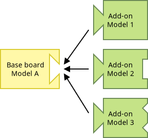
- Case 1: for a given base board with a connector, any addon having a compatible connector can be connected
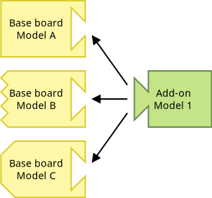
- Case 2: a given addon board can be connected to any base board with a compatible connector
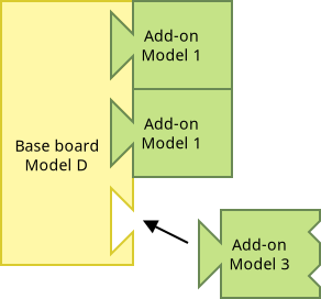
- Case 3: A base board can have several connectors, of the same of different types, and to each connector an addon can be connected independently of what happens on other connectors; this includes connecting two identical addons to two compatible connectors on the same base board
The central point to support all these cases is the connector. The connector is the contract between the two sides:
- the base board provides some resources on the connector: GPIOs, I²C and SPI busses, etc
- the addon uses some or all those resources.
To cleanly and efficiently describe all this we need a modular approach, where:
- a single device tree file describes a base board model and any compatible addon can be applied to it (case 1)
- one single device tree file describes an addon model and can be used unmodified on any base board with a compatible connector (case 2)
- an addon device tree file is usable unmodified on any connector of a multi-connector board (case 3).
So we need to decouple the base board and the addon descriptions:
- the base board describes what it provides on the connector (not how it implements it)
- the addon describes which resources on the connector it uses and how (not referring to how it is implemented by the base board).
What about Device Tree Overlays?
Before going further, readers could think about device tree overlays to describe the extension board. That’s exactly what we tried initially, but it didn’t work out.
The main reason overlays are not suitable for this task is that an overlay refers directly to symbols exported via labels from the base tree. Consider for example a base board with a connector that offers a GPIO line: the GPIO controller controlling the line is on the main board (e.g. gpio1) and the GPIO is used by a chip on the addon as a reset line. Using the board overlay dtso would refer to the GPIO controller (e.g. reset-gpios = <&gpio1 ...>). This does not scale: a different base board, or a different connector on the same board, could provide the same GPIO line using a different controller (e.g. gpio2) and thus the overlay would not work.
So we need to decouple the base board and the addon, and that’s what the connector contract does.
Another problem with that approach is that the base device tree exposes all the labels to overlays in a global namespace, and overlays refer to those labels. This is risky and error prone as it exposes a lot of information from the base tree that has nothing to do with the connector, and so it should not be accessible to addon boards and their overlay files.
Decoupling requires putting more information in the base device tree about the symbols that are meant to be exported to the addon board, and information in the overlay in order to resolve the symbols when the overlay is applied. Overlays already put similar information in special nodes (__symbols__, __fixups_ and __local_fixups__), so we proposed to add new nodes: export-symbols.
This was rejected because adding such information in nodes was a bad design even in the original device tree overlays: the device tree data (nodes and properties) indeed is meant to describe the hardware. Information to resolve symbols is something else, so we were asked to store it a new place: metadata. Metadata is stored in dtb files but not as part of the regular device tree nodes and properties. This was a fundamental addition to the device tree binary format.
Device tree addons
Our current proposal went past old device tree overlays and their limitations, and introduces a new concept: device tree addons. Addons are similar to overlay in principle, but very different in the technical details. Let’s understand them by looking at a small but realistic example.
Example hardware
Let’s assume a board vendor has designed a board with two connectors on which extension boards can be connected.
The board has two connectors, and the board vendor gives the following pinout for both — this is the connector contract:
| Pin | Description |
|---|---|
| Pin 1 | 3V3 supply |
| Pin 2,3 | I2C SCL, SDA |
| Pin 4 | GPIO #0 / IRQ #0 |
| Pin 5 | GPIO #1 / IRQ #1 |
| Pin 6 | GND |
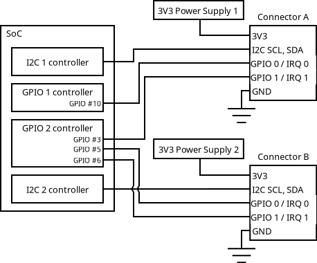
Here’s the base board schematics, showing how the mainboard implements the contract for each connector:
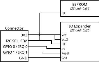
And here’s a simple addon board schematics, showing how this addon uses the features provided based on the contract. It has an EEPROM and an IO expander.
Base board description
The device tree source (.dts file) for the base board is mostly standard, except some new syntax, described below.
001 /* 3V3 Power Supply 1 */
002 regul1_3v3: regul1 {
003 compatible = "fixed-regulator";
004 ...
005 };
006
007 /* 3V3 Power Supply 2 */
008 regul2_3v3: regul2 {
009 compatible = "fixed-regulator";
010 ...
011 };
012
013 soc {
014 /* I2C 1 Controller */
015 i2c1: i2c@1000 {
016 compatible = "soc-vendor,i2c-ctrl";
017 ...
018 };
019
020 /* I2C 2 Controller */
021 i2c2: i2c@2000 {
022 compatible = "soc-vendor,i2c-ctrl";
023 ...
024 };
025
026 /* GPIO 1 Controller, also interrupt controller */
027 gpio1: gpio@4000 {
028 compatible = "soc-vendor,gpio-ctrl";
029 ...
030 gpio-controller;
031 #gpio-cells = <0x02>;
032 ...
033 interrupt-controller;
034 #interrupt-cells = <0x02>;
035 #address-cells = <0x00>;
036 ...
037 };
038
039 /* GPIO 2 Controller, also interrupt controller */
040 gpio2: gpio@5000 {
041 compatible = "soc-vendor,gpio-ctrl";
042 ...
043 gpio-controller;
044 #gpio-cells = <0x02>;
045 ...
046 interrupt-controller;
047 #interrupt-cells = <0x02>;
048 #address-cells = <0x00>;
049 ...
050 };
051 };
052
053 conn_a: conn-a {
054 compatible = "myvendor,myconnector";
055
056 /*
057 * Nexus node definition for GPIOs
058 *
059 * Map:
060 * - gpio 0 at connector to gpio1 10
061 * - gpio 1 at connector to gpio2 3
062 */
063 #gpio-cells = <2>;
064 gpio-map-mask = <0xf 0x0>;
065 gpio-map-pass-thru = <0x0 0xf>;
066 gpio-map = <0 0 &gpio1 10 0>,
067 <1 0 &gpio2 3 0>;
068
069 /*
070 * Nexus node definition for interrupts
071 *
072 * Map:
073 * - irq 0 at connector to the gpio1 irq 10
074 * - irq 1 at connector to the gpio2 irq 3
075 */
076 #address-cells = <0>;
077 #interrupt-cells = <2>;
078 interrupt-map =
079 <0 IRQ_TYPE_LEVEL_LOW &gpio1 10 IRQ_TYPE_LEVEL_LOW>,
080 <0 IRQ_TYPE_LEVEL_HIGH &gpio1 10 IRQ_TYPE_LEVEL_HIGH>,
081 <1 IRQ_TYPE_LEVEL_LOW &gpio2 3 IRQ_TYPE_LEVEL_LOW>,
082 <1 IRQ_TYPE_LEVEL_HIGH &gpio2 3 IRQ_TYPE_LEVEL_HIGH>;
083
084 /* The connector itself */
085 /export/ conn: &conn_a;
086
087 /* The 3v3 at Connector A: 3V3 Power Supply 1 */
088 /export/ supply_3v3: ®ul1_3v3;
089
090 /* The I2C at Connector A: I2C 1 Controller */
091 /export/ i2c: &i2c1;
092
093 /*
094 * Even if the exported 'conn' symbol is enough,
095 * make things clear and export a specific symbol
096 * for GPIOs pointing to the nexus node (i.e. the
097 * connector itself).
098 */
099 /export/ gpios: &conn_a;
100
101 /*
102 * As for GPIOs, make things clear and export a
103 * specific symbol for interrupts.
104 */
105 /export/ irq: &conn_a;
106 };
107
108 conn_b: conn-b {
109 compatible = "myvendor,myconnector";
110
111 /*
112 * Nexus node definition for GPIOs
113 *
114 * Map:
115 * - gpio 0 at connector to gpio2 5
116 * - gpio 1 at connector to gpio2 6
117 */
118 #gpio-cells = <2>;
119 gpio-map-mask = <0xf 0x0>;
120 gpio-map-pass-thru = <0x0 0xf>;
121 gpio-map = <0 0 &gpio2 5 0>,
122 <1 0 &gpio2 6 0>;
123
124 /*
125 * Nexus node definition for interrupts
126 *
127 * Map:
128 * - irq 0 at connector to the gpio2 irq 5
129 * - irq 1 at connector to the gpio2 irq 6
130 */
131 #address-cells = <0>;
132 #interrupt-cells = <2>;
133 interrupt-map =
134 <0 IRQ_TYPE_LEVEL_LOW &gpio2 5 IRQ_TYPE_LEVEL_LOW>,
135 <0 IRQ_TYPE_LEVEL_HIGH &gpio2 5 IRQ_TYPE_LEVEL_HIGH>,
136 <1 IRQ_TYPE_LEVEL_LOW &gpio2 6 IRQ_TYPE_LEVEL_LOW>,
137 <1 IRQ_TYPE_LEVEL_HIGH &gpio2 6 IRQ_TYPE_LEVEL_HIGH>;
138
139 /* The connector itself */
140 /export/ conn: &conn_b;
141
142 /* The 3v3 at Connector B: 3V3 Power Supply 2 */
143 /export/ supply_3v3: ®ul2_3v3;
144
145 /* The I2C at Connector B: I2C 2 Controller */
146 /export/ i2c: &i2c2;
147
148 /* The GPIO nexus node */
149 /export/ gpios: &conn_b;
150
151 /* The interrupt nexus node */
152 /export/ irq: &conn_b;
153 };
The first part of the device tree is nothing special or new, it’s classic device tree code:
- Lines 1-11 describe the power supplies on the base board
- Lines 13-51 describe the SoC components used to provide the I²C busses and GPIO/interrupt lines to the connectors
Things get interesting with the following two nodes, each describing one of the connectors. Let’s look at the conn-a node.
Lines 56-67 define a nexus node for GPIOs. This is not a new concept, it is already well-defined and used. The GPIOs at the connector are part of the contract, and as such they need a well-defined GPIO number for all instances of the connector. In our case we have GPIO #0 / IRQ #0 on pin 4 and GPIO #1 / IRQ #1 on pin 5, for both connectors. But GPIO #0 is provided by GPIO 10 of the gpio1 controller for connector A, while for connector B GPIO #0 is provided by GPIO 5 of the gpio2 controller. The nexus node allows the addon board to reference GPIO #0 and GPIO #1 of the connector, without needing to know the implementation details of each base board the addon can be connected to, nor of each connector of the same board. The “translation” will be done later.
So this is really describing how the base board is providing a feature to satisfy the connector contract.
Lines 69-82 define a nexus node for using the same GPIO pins as interrupts, so it is similar to the GPIO nexus node.
With the following lines it is time to introduce a proposed new DTS keyword, /export/!
Line 85 exports the connector node using the new /export/ keyword. This means the base board offers some features at the connector (the GPIOs and interrupts, via nexus nodes) via this node.
The syntax is /export/ <name>: <ref>; where:
-
<name>(connin the example) is the symbol name exposed to the addon. It is part of the contract between the base board and the addon board.<ref>(&conn_ain the example) is the reference to the node linked to the symbol. It is base-board-specific and not usable by the addon.
Line 88 uses again the /export/ keyword to export the regulator providing the power supply to the addon. This lets chips on the addon reference the regulator that provides voltage to them, for example to turn on and off the correct power supply when the addon chips need it.
Line 91 similarly exports the I²C bus that the base board connects to connector A, which is i2c1.
Lines 94-105 are not strictly needed, but allow using the GPIOs and interrupts on the addon with a clearer description. Indeed, referencing the connector with the conn symbol exported at line 136 is sufficient to reference the Nexus node from the addon. However having dedicated gpios and irq symbols make things clearer when such GPIOs or IRQs are referenced from the addon.
That’s all for connector A. As you can see it only exports the few symbols needed to expose to the addon the features provided on the connector pins. Other resources on the base board, not wired to the connector, won’t be accessible to the addon.
Lines 108-153 describe connector B in node conn_b. You can easily see it has the exact same structure as conn_a:
- The exported names (the connector contract) are the same: the number of GPIOs and interrupts, and the
conn,supply_3v3,i2c,gpiosandirqnames. This allows an addon device tree to be attached wither toconn_aorconn_b. - They way those exported symbols are provided however are different. For example,
i2cis provided byi2c2for connector B, not byi2c1.
With the base board described, and most notably the connector contract defined thanks to the new /export/ keyword, we can now describe the addon board.
Addon board description
Similarly to device tree overlays .dtso files, we are using a new device tree file format for addons, having the .dtsa extension and some new keywords and syntax.
Unlike device tree overlays, a device tree addon is always applied to a single node of the underlying device tree. That’s the connector node. This is a natural description of the hardware: an addon board is physically connected to a connector and can only access resources wired to that connector. The device tree addon description maps the physical reality.
Here’s how our simple addon can be described in a dtsa file:
001  /*
002   * Import only the connector and use namespace
003   * symbol references
004   */
005  /import/ conn: "";
006
007  &conn.i2c {
008  	 io-expander@20 {
009  	     compatible = "foo,io-expander";
010  	     reg = <0x20>;
011  	     vcc1-supply = <&conn.supply_3v3>;
012  	     ...
013  	     reset-gpios = <&conn.gpios 1 GPIO_ACTIVE_LOW>;
014  	     interrupt-parent = <&conn.irq>;
015  	     interrupts = <0 IRQ_TYPE_LEVEL_LOW>;
016  	 };
017
018  	 eeprom@52 {
019  	     compatible = "foo,eeprom";
020  	     reg = <0x52>;
021  	     ...
022  	 };
023  };
Line 5 is using the new /import/ keyword to import a symbol from the connector. This is the counterpart of the /export/ keyword.
The syntax is: /import/ <name>: <compatible>; where:
<name>is the symbol name used by the addon. It is part of the contract between the base board and the addon board.<compatible>is a compatible string that can be used during symbol resolution to identify the kind of node pointed to by the symbol name. It can be set as an empty string for the common cases (see below).
Imported symbols have to match symbols exported by the node to which the addon will be applied (the connector node).
Using the same name on both sides is the simple way to perform this match, but some use cases have been identified where names are not sufficient. Attaching a compatible string to imported symbols helps with the matching criteria. For instance, we can imagine /import/ foo_bus: "bus,i2c"; to state that foo_bus has to be an I2C bus.
Furthermore, this compatible string could also be used in device tree checks against bindings. Based on the compatible strings of imported symbols, the use of the symbol by the addon could then be checked.
Line 7 starts the decription of what is on the I²C bus in the addon, and it does so introducing a new syntax: namespaced symbols. The &conn.i2c string intuitively reads: a phandle referring to the I²C bus exposed by the connector node, and that’s correct in the practice. It works thanks to the /export/ i2c: &...; line in the connector description, which exports the i2csymbol within the connector symbol namespace, because it is inside the connector node.
This mechanism allows specific parts of what the connector contract exposes, like specific busses and pins, to be imported by the addon with a concise and readable syntax.
Lines 8-16 define the IO expander on the addon board. It is a standard device tree description for an I²C device. What’s relevant here is that it accesses resources provided by the base board over the connector, again using namespaced symbols: &conn.supply_3v3 and &conn.irq to access exported nodes, and &conn.gpios 1 GPIO_ACTIVE_LOW to access a GPIO exposed by the GPIO nexus node.
Lines 18-22 finally describe the EEPROM on the I²C node. There is nothing new here compared to regular device tree syntax.
Try it yourself
Our current work is currently focused on the new file formats and the libfdt/dtc code, and is visible on the devicetree-compiler mailing list, in these two patch series:
- A preliminary series, adding features to the binary DTB format to be more future-proof:
[PATCH v3 00/15] Add support for structured tags and v18 dtb version. - The main series adding addon support, depending on the previous one:
[RFC PATCH v2 00/74] Add support for dtb metadata and addon device-trees.
To allow you easily test our current work we created a fork of the dtc git repository with the two patch series applied. Follow these instructions to try it out.
Fetch the code and compile
All the needed modifications in dtc/libfdt are available on the Bootlin fork of the dtc repository. Here’s how to get the code and test it.
# Get the source
$ git clone https://github.com/bootlin/dtc.git
$ cd dtc
# Use the code corresponding to the latest series sent upstream
# (i.e. the bootlin/support-for-addon-rfc-v2 branch)
$ git checkout -b support-for-addon-rfc-v2 \
                  origin/bootlin/support-for-addon-rfc-v2
# Setup the build directory
$ meson setup builddir/
# Compile
$ meson compile -C builddir/
# Run internal tests (if you want to)
$ meson test -C builddir/
The compiled binaries are available in the builddir directory. To be sure everything is correct, you can check the dtc version:
$ ./builddir/dtc --version
Version: DTC v1.8.1-108-gc68038e
Apply an addon dtsa file
Several base dts and addon dtsa files are available in the tests directory.
They are used for the internal tests, but fdtaddon_realistic_base.dts (base board description) and fdtaddon_realistic_addon.dtsa (extension board description) could be interesting as a starting point.
Compile dts and dtsa files (the syntax is exactly the same for both):
$ ./builddir/dtc -I dts -O dtb -o /tmp/base.dtb \
                 ./tests/fdtaddon_realistic_base.dts
$ ./builddir/dtc -I dts -O dtb -o /tmp/addon.dtba \
                 ./tests/fdtaddon_realistic_addon.dtsa
Benefits of the new metadata
These device tree blobs can be converted back to dts to understand what was done… with a little surprise! Let’s have a look at the output of deciding the main device tree blob:
$ ./builddir/dtc -I dtb -O dts /tmp/base.dtb
In the output you may notice:
/dts-v1/;

/ {
    regulator {
        compatible = "regulator-fixed";
        gpios = <&{/soc/gpio@2000} 0x05 0x00>;
        ...
Here properties using a phandle value is converted back using a reference by path (&{/soc/gpio@2000}) instead of a number as you would see with current device tree code. This is a benefit of the proposed addition of metadata to the dtb file.
You can also notice the /export/ed symbols are clearly visible in the decoded device tree, again thanks to the new metadata:
    connector-a {
       /export/ connector: &{/connector-a};
       /export/ conn_i2c: &{/connector-a/conn-i2c};
       /export/ conn_5v: &{/regulator};
       ...
    };
Now let’s decode the addon dtba file:
$ ./builddir/dtc -I dtb -O dts /tmp/addon.dtba
In the decoded output you can see both the imported symbols and the readable phandles as before, and namespaced symbols are decoded in a readable manner as well:
/import/ connector: "abc,foo-connector";
/import/ conn_5v: "";

&connector {
   conn-i2c {
       gpio@23 {
           vcc1-supply = <&conn_5v>;
           vcc2-supply = <&connector.conn_5v>;
           reset-gpios = <&connector 0x01 0x00>;
           ...
       };
   };
};
Even more info from fdtdump
To get even more information decoded from the dtb and dtba files, the fdtdump debug tool has been extended as well to show the metadata present in the new binary format. For the curious:
$ ./builddir/fdtdump /tmp/base.dtb
$ ./builddir/fdtdump /tmp/addon.dtba
The new fdtaddon tool
To apply an addon device tree blob (dtba) we propose a new tool: fdtaddon
$ ./builddir/fdtaddon --help
Usage: apply an addon to a base blob
    fdtaddon

Options: -[i:o:t:e:vhV]
  -i, --input   Input base DT blob
  -o, --output  Output DT blob
  -t, --target  Target node
  -e, --export  Custom export symbol
    Multiple --export or -e can be present in order to export
    multiple symbols.
    The following syntaxes are supported:
      - Defines an export symbol pointing to a node using its
        symbol
          --export '=&'
      - Defines an export symbol pointing to a node by path
          --export '=&{path_to_node}'
  -v, --verbose      Verbose messages
  -h, --help         Print this help and exit
  -V, --version      Print version and exit
$
Let’s apply the generated addon.dtba to base.dtb. Remember an addon is applied to a specific node in the base tree, which is the connector node. A base board could have more than one, so we need to point to the desired one.
In the example base device tree the connector is available at the /connector-a node, so we can apply the addon to that connector node:
$ ./builddir/fdtaddon -i /tmp/base.dtb -o /tmp/merged.dtb \
                      -t "/connector-a" /tmp/addon.dtba
The resulting dtb is the merged.dtb file. This file can be converted back to dts to be reviewed:
$ ./builddir/dtc -I dtb -O dts /tmp/merged.dtb
The resulting merged.dtb file describes the base board with the addon connector to Connector A.
When can I use it for my project? (aka: roadmap and current status)
The new features we proposed, including a new .dts syntax and a new binary format version, touch a foundational component so many embedded systems rely on in the industry. Should you suspect this is not a short and easy path, you’d be right.
We presented our initial proposal at Linux Plumbers Conference 2024, an improved prototype on mailing lists in May 2025, which got discussed with the community during ELCE 2025 and a follow-up mailing discussion. That old approach has been rejected, because it was based on device tree overlays. The discussion led to the current idea.
Right now we are working to the foundation of the new idea in the libfdt/dtc code, which we are presenting here.
The two series mentioned above implement all of what is mentioned in this blog post: the additions to the dts syntax, the extension to the binary blob format and the new dtsa file format. Now discussion is in progress to agree on the new source and binary formats as well as the implementation details.
Once the source and binary format will have been agreed on, the future steps in the roadmap include:
- Update the Device Tree Specification with the new
dtskeywords and newdtbtags. - Minimal support in U-Boot to parse the new v18 DTB format: this is quite simple, U-Boot just needs to know about the new binary format and ignore the new optional tags;
- Addon support in the Linux kernel: this will allow the kernel to apply an addon file at runtime, supporting both coldplug and hotplug use cases; this is more complex than the U-Boot work but we can leverage the experience achieved while working on our previous prototypes;
- Other bootloaders and operating systems are not on our roadmap, but are doable after the previous ones establish the base practice.
Clearly the approval on the new syntax and dtb format is a blocking step before having any chance of Linux or any other software to use the new format. That’s where your 🫵 feedback can help our work move forward!
Follow the above instructions to test the new features using the fdtaddon tool, then reply to the main series and let the community know; you can give your Tested-by: to both series if it works or your use case. Writing real addon dts and dtsa files for your board and checking the merged dtb works on the hardware would be awesome!
Remember, this is a community work and community feedback is fundamental, especially for changes at the foundational bricks of the ecosystem.
Upcoming discussion opportunities: conferences next October in Prague
Community discussion does not stop at mailing lists. Experience tells complex topics are better discussed face to face.
For this reason I will be participating to both the Linux Plumbers Conference 2026 and the Embedded Linux Conference Europe 2026 next October in Prague. These are two great opportunities for discussion with the community.
And because this topic is very complex and needs discussion on various aspects, I will be leading a discussion session during Linux Plumbers Conference: Device Tree Addons: Describe hot-pluggable extension boards.
If you are going at one of these conferences and you have any comments, questions or use cases to discuss, but cannot attend the discussion session, don’t hesitate to contact me in advance or grab me in the hallway.
Conclusion
Concluding, the use case of extension boards connected to connectors available on different base boards is a common one in the embedded world, and the industry and communities have long been waiting for a solution that is not yet available.
The device tree addon work presented here offers a well-structured solution covering even complex use cases in a clean and effective way. The road is still long but with community involvement progress can happen in the near future, to hopefully provide a fully upstream solution in the near future.
Again, you can help by providing your feedback: don’t hesitate to report your feedback and use cases in reply to the main patch series.