![]() This post is our third blog post in our series about Zephyr. You can check our previous episodes: Getting started with Zephyr and Understanding Zephyr’s Blinky Sample. In this third blog post, we will see how to implement a device driver for Zephyr, from the configuration of the build system, the code of the driver itself, to contributing the driver upstream.
This post is our third blog post in our series about Zephyr. You can check our previous episodes: Getting started with Zephyr and Understanding Zephyr’s Blinky Sample. In this third blog post, we will see how to implement a device driver for Zephyr, from the configuration of the build system, the code of the driver itself, to contributing the driver upstream.
Introduction
First, we had to find a device suitable for writing a device driver. After looking at all the components on the Arduino Nano 33 BLE board, we noticed that the inertial sensor, the LSM9DS1 from ST, was not supported in Zephyr, so we set ourselves the goal of developing a driver for this device.
The LSM9DS1 sensor is a 9-axis inertial module: it is composed of an accelerometer, a gyroscope, and a magnetometer. It can be used connected to either an I²C or an SPI interface. On the Arduino board, the sensor is connected to an I²C interface.
Preparation
To be able to test our driver, the first step is to create an application. As described in our previous blog post, the easiest way is to copy the code of a sample: cp -r samples/basic/blinky project_lsm9ds1, and then to add the correct app.overlay to have the console over USB:
/ {
    chosen {
        zephyr,console = &cdc_acm_uart0;
    };
};

&zephyr_udc0 {
    cdc_acm_uart0: cdc_acm_uart0 {
        compatible = "zephyr,cdc-acm-uart";
    };
}
In the prj.conf, you have to add the options to activate USB, but also the sensor subsystem:
CONFIG_USB_DEVICE_STACK=y
CONFIG_USB_DEVICE_INITIALIZE_AT_BOOT=y

CONFIG_SENSOR=y
We will just have to change the main.c to test our driver.
Hardware description and Device Tree
In Zephyr, the drivers know which devices exist thanks to the Device Tree, a data structure that describes the hardware on your platform. So before writing the driver, we need to describe our device to the Device Tree.
First, you need to create a Device Tree Binding: it’s a specification that describes the structure of the Device Tree node for your device. In this file, you have to put a description of your device, the list of properties supported, and, most importantly, the compatible string for your device. For the LSM9DS1, the compatible is st,lsm9ds1.
The bindings are stored in dts/bindings. The LSM9DS1 is a sensor, so the driver is part of the sensor subsystem. Our binding will be stored in dts/bindings/sensor/st,lsm9ds1.yaml. The binding will look like this:
description: |
    STMicroelectronics LSM9DS1 9-axis IMU (Inertial Measurement Unit) sensor
    accessed through I2C bus.
    ...

compatible: "st,lsm9ds1"

include: [sensor-device.yaml, i2c-device.yaml]

properties:
    ...
Now we have to write the actual description of the device in the Device Tree. On our board, the sensor is connected to the i2c1 bus. To add it to the Device Tree, we have to find its slave address. For that, we have to look at the datasheet of the LSM9DS1. The answer is on page 30: in table 19 we see the address of the accelerometer and gyroscope, and the address of the magnetometer in table 20.
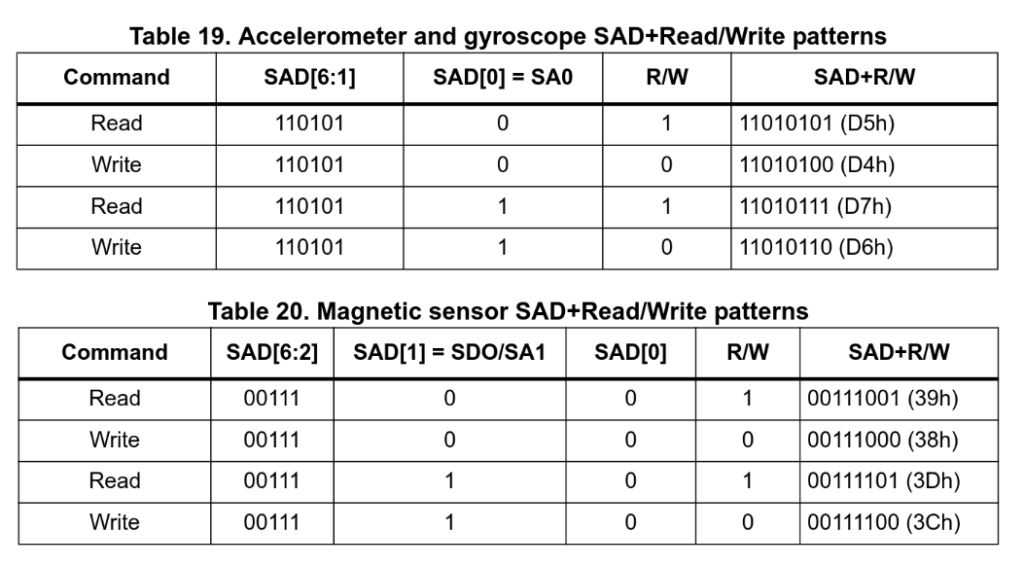
For now, we will only focus on the accelerometer and gyroscope part. We can see that the address, is either 0b1101010 or 0b1101011, depending on the value given to the pin SA0, which in hexadecimal is 0x6a or 0x6b. We now have to find which value is on this pin: the datasheet says that the value of SA0 comes from the pin SDO_A/G.
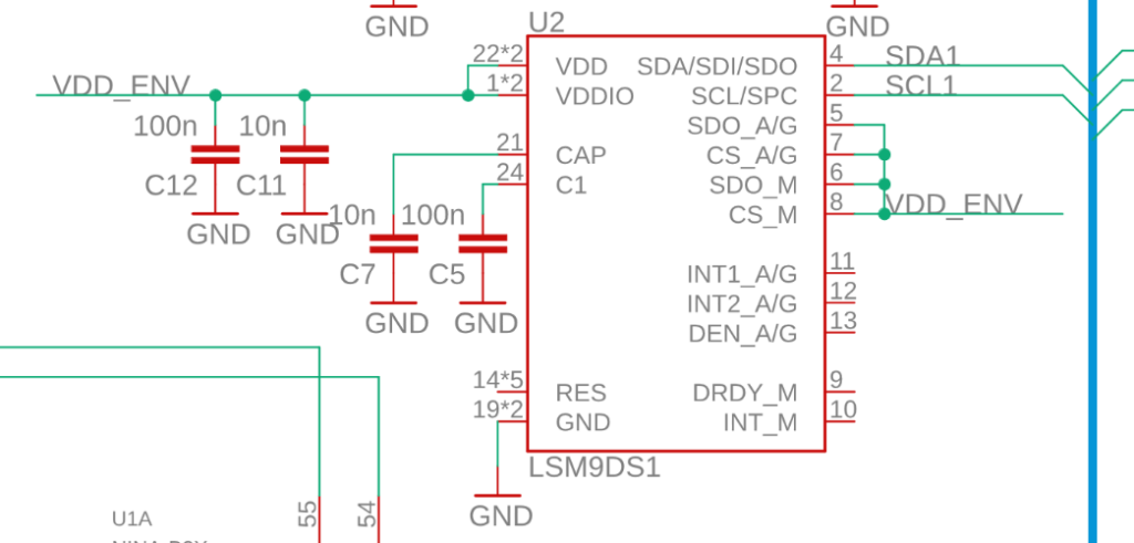
We can now look at the schematics of the board, where we see that this pin is set to VDD: a logical 1. So the slave address is 0x6b.
We now have all the information needed for writing our Device Tree description. We will put it in the app.overlay:
&i2c1 {
    lsm9ds1: lsm9ds1@6b {
        compatible = "st,lsm9ds1";
        reg = <0x6b>;
    };
};
We have two properties: the compatible, which tells what the device is, and the reg property, which tells which values you can use to address the device. In our case, it’s just the slave address on the I²C bus.
We now have to configure the build system, to be able to compile our driver when needed.
Setting up the build system
Before implementing our driver code, we have to let the KConfig configuration system and CMake know about our new driver. For that, in the folder drivers/sensor, we have to create a folder named lsm9ds1, with two files: Kconfig and CMakeLists.txt. The first one allows to enable the driver in the Zephyr configuration, the second one allows to describe what files need to be built.
The Kconfig file will look like this:
config LSM9DS1
    bool "LSM9DS1 I2C accelerometer and gyroscope chip"
    default y
    depends on DT_HAS_ST_LSM9DS1_ENABLED
    select I2C
    select HAS_STMEMSC
    select USE_STDC_LSM9DS1
This file creates the Kconfig option CONFIG_LSM9DS1, and enables I2C, but also the HAL (Hardware Abstraction Layer) that our driver will use.
Then, we have to modify drivers/sensor/Kconfig to include our new Kconfig file:
source "drivers/sensor/st/lsm9ds1/Kconfig"
The CMakeLists.txt will look like this:
zephyr_library()

zephyr_library_sources(lsm9ds1.c)

zephyr_library_include_directories(../stmemsc)
This is just a simple file that tells CMake to compile our file lsm9ds1.c.
And finally, we have to modify drivers/sensor/CMakeLists.txt to conditionally compile our code, if the right Kconfig option is enabled.
add_subdirectory_ifdef(CONFIG_LSM9DS1 lsm9ds1)
We can now start coding our driver, in drivers/sensor/lsm9ds1/lsm9ds1.c.
Writing and testing the driver
The first thing to do is to define the macro DT_DRV_COMPAT: it tells Zephyr what Device Tree compatible string our driver supports. You’ll note that the comma in the compatible string visible in the Device Tree is replaced here by an underscore.
#define DT_DRV_COMPAT st_lsm9ds1
Our driver will instantiate a struct device, the struct representing a device at runtime.
The struct device is defined as follows:
struct device {
    /** Name of the device instance */
    const char *name;
    /** Address of device instance config information */
    const void *config;
    /** Address of the API structure exposed by the device instance */
    const void *api;
    /** Address of the common device state */
    struct device_state *state;
    /** Address of the device instance private data */
    void *data;
};
The struct device_state is there to know if the device is initialized or not yet: it’s handled by the rest of the OS. The name is derived from the Device Tree node.
So we have to handle the config, the data, and the api fields. The config field contains configuration data, set at build-time. The data field contains data that needs to be modified at runtime. The api field contains the function implementing the subsystem API that our device uses. In our case, as our device is a sensor, it’s the sensor_driver_api.
That means that in our driver we will have:
struct lsm9ds1_config {
    // Config properties of the device
};

struct lsm9ds1_data {
    // Data of the device
};

static const struct sensor_driver_api lsm9ds1_api_funcs = {
    // Our API functions
};
We also need an init function, that will be called during boot:
static int lsm9ds1_init(const struct device *dev)
{
    printf("Initializing lsm9ds1\n");
    return 0;
}
Now, as indicated in the documentation, we need to set up the macros that will create and initialize the struct device.
First, we need a macro that initializes the two structs, and then call the macros responsible for creating the struct device. Normally, we would use DEVICE_DT_INST_DEFINE, but as we are doing a driver for a sensor, we will use SENSOR_DEVICE_DT_INST_DEFINE. This macro will call DEVICE_DT_INST_DEFINE, and register your device into a list of all sensors. Our macro will take as argument an instance number. That means that our driver is able to support, if needed, multiple devices at the same time.
#define LSM9DS1_DEFINE(inst)                              \
    static struct lsm9ds1_data lsm9ds1_data_##inst = {    \
    };                                                    \
                                                           \
    static struct lsm9ds1_config lsm9ds1_config_##inst = { \
    };                                                     \
                                                           \
    SENSOR_DEVICE_DT_INST_DEFINE(inst, lsm9ds1_init, NULL, &lsm9ds1_data_##inst,    \
                     &lsm9ds1_config_##inst, POST_KERNEL,   \
                     CONFIG_SENSOR_INIT_PRIORITY, &lsm9ds1_api_funcs);
Then, we just have to use a macro that will call LSM9DS1_DEFINE for each node in the device tree with the right compatible string:
DT_INST_FOREACH_STATUS_OKAY(LSM9DS1_DEFINE);
Now, if we compile and run our app, we should see, before the start of our application, our printf:
Initializing lsm9ds1
*** Booting Zephyr OS build v3.7.0-rc1-5-ged3d2ad9f329 ***
All the infrastructure is now in place, but, for now, we haven’t communicated at all with our device.
So the first step is to implement the init() function, which will have to start the sensor, and configure it so that we can read values.
If we read the datasheet of the sensor, we see that we have to write some specific registers to interact with it. But we don’t have to do all the steps manually: there is a HAL (Hardware Abstraction Layer) in Zephyr, that allows us to interact with the sensor more easily. It’s stored in modules/hal/st/sensor/stmemsc/lsm9ds1_STdC/driver/lsm9ds1_reg.c, in your zephyrproject directory. In this file (and the header, lsm9ds1_reg.h) there is a lot of helper functions, the definition of all registers, etc.
As the lsm9ds1 can be plugged on different buses (I²C and SPI), the HAL can’t know how to access the registers. That’s why it uses a “context” structure, which provides the functions needed to interact with the sensor. In Zephyr, there are some files to help us use this API, in drivers/sensor/stmemsc.
We will have to add two fields in our struct lsm9ds1_config: a field stmdev_ctx_t ctx; with the function used to access the sensor, and a field union stmemsc_cfg, which should be a type const struct i2c_dt_spec i2c; if the device is plugged on an I²C bus, and const struct spi_dt_spec spi; if the bus is SPI.
So the struct lsm9ds1_config now look like this:
struct lsm9ds1_config {
    stmdev_ctx_t ctx;
    union {
#if DT_ANY_INST_ON_BUS_STATUS_OKAY(i2c)
        const struct i2c_dt_spec i2c;
#endif
#if DT_ANY_INST_ON_BUS_STATUS_OKAY(spi)
        const struct spi_dt_spec spi;
#endif
    } stmemsc_cfg;
};
The macros allow the preprocessor to select the right bus.
We now have to modify our macro LSM9DS1_DEFINE to support the new fields. As on the Arduino Nano 33 BLE the lsm9ds1 is connected on the I²C bus, we made the decision to only support I²C. We can use the macros defined by the stmemsc driver to initialize the stmdev_ctx_t:
#define LSM9DS1_CONFIG_I2C(inst)                                   \
    {                                                             \
        STMEMSC_CTX_I2C(&lsm9ds1_config_##inst.stmemsc_cfg),     \
        .stmemsc_cfg =                                            \
            {                                                     \
                .i2c = I2C_DT_SPEC_INST_GET(inst),                \
            },                                                    \
    }


#define LSM9DS1_DEFINE(inst)                                    \
    static struct lsm9ds1_data lsm9ds1_data_##inst = {         \
    };                                                         \
                                                               \
    static struct lsm9ds1_config lsm9ds1_config_##inst = LSM9DS1_CONFIG_I2C(inst);    \
                                                               \
    SENSOR_DEVICE_DT_INST_DEFINE(inst, lsm9ds1_init, NULL, &lsm9ds1_data_##inst,   \
                     &lsm9ds1_config_##inst, POST_KERNEL,      \
                     CONFIG_SENSOR_INIT_PRIORITY, &lsm9ds1_api_funcs);
We can now try to reboot the sensor: the datasheet says that to reboot the sensor we have to set to 1 a bit in the register CTRL_REG8.
We can use the functions lsm9ds1_read_reg and lsm9ds1_write_reg and the register definition of the HAL:
static int lsm9ds1_reboot(const struct device *dev)
{
    const struct lsm9ds1_config *cfg = dev->config;
    stmdev_ctx_t *ctx = (stmdev_ctx_t *)&cfg->ctx;
    lsm9ds1_ctrl_reg8_t ctrl8_reg;
    int ret;

    ret = lsm9ds1_read_reg(ctx, LSM9DS1_CTRL_REG8, (uint8_t *)&ctrl8_reg, 1);
    if (ret < 0) {
        return ret;
    }

    ctrl8_reg.boot = 1;

    ret = lsm9ds1_write_reg(ctx, LSM9DS1_CTRL_REG8, (uint8_t *)&ctrl8_reg, 1);
    if (ret < 0) {
        return ret;
    }

    k_msleep(50);

    return 0;
}
After that, we need to set a sampling frequency for the accelerometer and gyroscope: by default, it’s set at 0Hz: the sensor is not doing anything. But the sensor supports multiple sampling frequencies: how to choose the one we want?
The best solution is to let the user decide. For that, we will use the Device Tree: the user will only have to set a property in an overlay to be able to set the sampling frequency at the value he wants.
So in the binding (dts/bindings/sensor/st,lsm9ds1.yaml), we have to add our property. As only some specific values are correct, we gave them names, defined in a header. That way, you just have to include the header in your overlay, and put the name of the value you want. We put in the description the names of the different values.
properties:

  imu-odr:
    type: int
    default: 0
    description: |
      Specify the default accelerometer and gyroscope output data rate expressed in samples
      per second (Hz).
      Default is power-up configuration.

      - 0x00 # LSM9DS1_IMU_OFF
      - 0x10 # LSM9DS1_GY_OFF_XL_10Hz
      - 0x20 # LSM9DS1_GY_OFF_XL_50Hz
      - 0x30 # LSM9DS1_GY_OFF_XL_119Hz
      - 0x40 # LSM9DS1_GY_OFF_XL_238Hz
      - 0x50 # LSM9DS1_GY_OFF_XL_476Hz
      - 0x60 # LSM9DS1_GY_OFF_XL_952Hz
      - 0x01 # LSM9DS1_XL_OFF_GY_14Hz9
      - 0x02 # LSM9DS1_XL_OFF_GY_59Hz5
      - 0x03 # LSM9DS1_XL_OFF_GY_119Hz
      - 0x04 # LSM9DS1_XL_OFF_GY_238Hz
      - 0x05 # LSM9DS1_XL_OFF_GY_476Hz
      - 0x06 # LSM9DS1_XL_OFF_GY_952Hz
      - 0x11 # LSM9DS1_IMU_14Hz9
      - 0x22 # LSM9DS1_IMU_59Hz5
      - 0x33 # LSM9DS1_IMU_119Hz
      - 0x44 # LSM9DS1_IMU_238Hz
      - 0x55 # LSM9DS1_IMU_476Hz
      - 0x66 # LSM9DS1_IMU_952Hz
      - 0x81 # LSM9DS1_XL_OFF_GY_14Hz9_LP
      - 0x82 # LSM9DS1_XL_OFF_GY_59Hz5_LP
      - 0x83 # LSM9DS1_XL_OFF_GY_119Hz_LP
      - 0x91 # LSM9DS1_IMU_14Hz9_LP
      - 0xA2 # LSM9DS1_IMU_59Hz5_LP
      - 0xB3 # LSM9DS1_IMU_119Hz_LP

    enum: [0x00, 0x10, 0x20, 0x30, 0x40, 0x50, 0x60, 0x01, 0x02, 0x03, 0x04, 0x05, 0x06, 0x11,
           0x22, 0x33, 0x44, 0x55, 0x66, 0x81, 0x82, 0x83, 0x91, 0xA2, 0xB3]
And then add this into the overlay:
&lsm9ds1 {
    imu-odr = <LSM9DS1_IMU_14Hz9>;
};
Now, in our driver, we have to add a field in our struct lsm9ds1_config:
uint8_t imu_odr;
For the macros that create the struct, we put this kind of configuration in a macro called LSM9DS1_CONFIG_COMMON, that we call in LSM9DS1_CONFIG_I2C. That way, if someone wants to port the driver to use SPI, they will have only minimal work.
#define LSM9DS1_CONFIG_COMMON(inst)                      \
    .imu_odr = DT_INST_PROP(inst, imu_odr)

/*
 * Instantiation macros used when a device is on an I2C bus.
 */

#define LSM9DS1_CONFIG_I2C(inst)                               \
    {                                                          \
        STMEMSC_CTX_I2C(&lsm9ds1_config_##inst.stmemsc_cfg),   \
        .stmemsc_cfg =                                         \
            {                                                  \
                .i2c = I2C_DT_SPEC_INST_GET(inst),             \
            },                                                 \
        LSM9DS1_CONFIG_COMMON(inst)                            \
    }
Then, in the init() function, we have to first call our reboot function, then set the output data rate:
static int lsm9ds1_init(const struct device *dev)
{
    const struct lsm9ds1_config *cfg = dev->config;
    stmdev_ctx_t *ctx = (stmdev_ctx_t *)&cfg->ctx;
    int ret;

    ret = lsm9ds1_reboot(dev);
    if (ret < 0) {
        LOG_ERR("Failed to reboot device");
        return ret;
    }

    LOG_DBG("output data rate is %d\n", cfg->imu_odr);
    ret = lsm9ds1_imu_data_rate_set(ctx, cfg->imu_odr);
    if (ret < 0) {
        LOG_ERR("failed to set IMU odr");
        return ret;
    }
}
Notice that we use a HAL function,lsm9ds1_imu_data_rate_set(), which will modify all the necessary registers to set at the same time the data rate of the accelerometer and the gyroscope.
We do the same for two other properties, the scale of the measurement (sensitivity) for both the accelerometer and the gyroscope.
Finally, we have to implement the API functions. For a sensor, the two minimum API functions to implement are sample_fetch() and channel_get(). sample_fetch() asks the driver to fetch data from the sensor, and to store it into an internal buffer. channel_get asks the driver for the data, in the channel asked.
To make sample_fetch, we have to create a buffer to store the sample. We can use our struct lsm9ds1_data. We will only show the code for the accelerometer, as the gyroscope follows a similar logic. The lsm9ds1 sensor gives us data as three 16-bit integers, representing the value of the acceleration on the 3 axes.
struct lsm9ds1_data {
    int16_t acc[3];
};
Then, the lsm9ds1_sample_fetch() function will just call different functions depending on the channel asked:
static int lsm9ds1_sample_fetch(const struct device *dev, enum sensor_channel chan)
{
    switch (chan) {
    case SENSOR_CHAN_ACCEL_XYZ:
        lsm9ds1_sample_fetch_accel(dev);
        break;
    case SENSOR_CHAN_GYRO_XYZ:
        lsm9ds1_sample_fetch_gyro(dev);
        break;
    case SENSOR_CHAN_ALL:
        lsm9ds1_sample_fetch_accel(dev);
        lsm9ds1_sample_fetch_gyro(dev);
        break;
    default:
        return -ENOTSUP;
    }
    return 0;
}
The function lsm9ds1_sample_fetch_accel() is simple: it only has to call a HAL function, passing the buffer to store the data.
static int lsm9ds1_sample_fetch_accel(const struct device *dev)
{
    const struct lsm9ds1_config *cfg = dev->config;
    stmdev_ctx_t *ctx = (stmdev_ctx_t *)&cfg->ctx;
    struct lsm9ds1_data *data = dev->data;
    int ret;

    ret = lsm9ds1_acceleration_raw_get(ctx, data->acc);
    if (ret < 0) {
        LOG_DBG("Failed to read sample");
        return ret;
    }

    return 0;
}
We then need to implement lsm9ds1_channel_get(). The main problem here is to convert the value: we have it as an integer on 16 bits, where the unit depends on the sensitivity, and we need to return it as a struct sensor_value. For the accelerometer, that means that we have to convert our value to m/s², with an integer part, and a fractional part, in µm/s².
The sensor can have different sensitivities, configurable with the Device Tree in the same way as the frequency of sampling. The datasheet gives us the value of the sensitivity for the different full-scale values: if the sensor can measure up to ±2g, the acceleration is given with a sensitivity of 0.061 mg/LSB (least significant bit): if you do +1 to the value, it means the acceleration is greater by 0.000061 times g.
To get the sensitivity, we use an array, indexed by the value that we put in the device tree, the “raw” full scale value :
/* Sensitivity of the accelerometer, indexed by the raw full scale value. Unit is µg/LSB */
static const uint16_t lsm9ds1_accel_fs_sens[] = {61, 732, 122, 244};
We store this value in a new field in our struct lsm9ds1_data :
uint32_t acc_gain;
To do the final conversion, we use the function sensor_ug_to_ms2, which as the name says, converts from µg to m/s². So, after some boilerplate functions (like lsm9ds1_channel_get(), which will just call the function for the accelerometer or gyroscope as needed), the end result is this function, with sensitivity being data->acc_gain.
static inline void lsm9ds1_accel_convert(struct sensor_value *val, int raw_val, uint32_t sensitivity)
{
    /* Sensitivity is exposed in ug/LSB */
    /* Convert to m/s^2 */
    sensor_ug_to_ms2(raw_val * sensitivity, val);
}
Now we have all the functions needed to make our driver work.
We just have to populate our API struct:
static const struct sensor_driver_api lsm9ds1_api_funcs = {
    .sample_fetch = lsm9ds1_sample_fetch,
    .channel_get = lsm9ds1_channel_get,
};
We can test the driver with this code in our application:
static void fetch_and_display(const struct device *dev)
{
    struct sensor_value x, y, z;
    static int trig_cnt;

    /* lsm6dso accel */
    sensor_sample_fetch_chan(dev, SENSOR_CHAN_ACCEL_XYZ);
    sensor_channel_get(dev, SENSOR_CHAN_ACCEL_X, &x);
    sensor_channel_get(dev, SENSOR_CHAN_ACCEL_Y, &y);
    sensor_channel_get(dev, SENSOR_CHAN_ACCEL_Z, &z);

    printf("accel x:%f ms/2 y:%f ms/2 z:%f ms/2\n",
            (double)out_ev(&x), (double)out_ev(&y), (double)out_ev(&z));

}

int main(void)
{
    const struct device *const dev = DEVICE_DT_GET_ONE(st_lsm9ds1);

    if (!device_is_ready(dev)) {
        printk("%s: device not ready.\n", dev->name);
        return 0;
    }

    while (1) {
        fetch_and_display(dev);
        k_msleep(1000);
    }
}
We should see the values of the acceleration every second on the console.
If we want to test the code using a sample from zephyr, to be sure that it works as intended, we just have to add this alias to the app.overlay
aliases {
    accel0 = &lsm9ds1;
};
and then build and flash the sample accel_polling. By doing that, it’s possible to confirm that our driver works well with the Zephyr API.
Contributing the driver
Once the driver is written and working, the next step is to contribute it upstream to the Zephyr project. This way, the driver will be useful to anyone trying to use it on the Arduino Nano 33 BLE or on any other board with this sensor. One of the changes to do was to move the declaration of the LSM9DS1 sensor in the device tree of the board directly, instead of in an overlay.
Then, to be able to submit a pull request to the Zephyr project on GitHub, we have to fork it. Then, we had to split my changes into multiple logical commits and commit them on a branch created for this driver. After pushing them to our fork, the next step is easy: you just have to click the big green button Compare & pull request and write a title and a message explaining your code.
Then, we have to answer the comments of the different maintainers before having the code merged into Zephyr.
The complete code of our pull request and the comments from the Zephyr maintainers are available on GitHub.
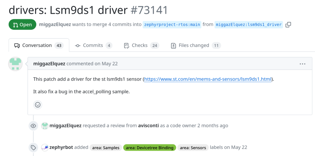
Our contributions contains 4 commits:
- One fixing the existing accel_polling example application
- One adding the Device Tree binding
- One adding the driver itself
- One adding the Device Tree description of the LSM9DS1 for the Arduino Nano 33 BLE board
Conclusion
We hope this blog post has helped our readers understand better how to write a driver for the Zephyr operating system, and contribute it upstream. Stay tuned for more Zephyr related blog posts!
Will doing this out-of-tree break the sensor shell inclusion?
I haven’t tried it, but it shouldn’t break sensor shell support as long as the driver is implemented correctly. An out-of-tree driver should function the same as an in-tree one if everything is set up properly.