![]() This post is the sixth in our series about Zephyr. You can find the previous episodes below:
This post is the sixth in our series about Zephyr. You can find the previous episodes below:
- Getting started with Zephyr
- Understanding Zephyr’s Blinky example
- Zephyr: Implementing a Device Driver for a sensor
- Integrating ST7789H2 Display Support on STM32L562E-DK with Zephyr: A Step-by-Step Guide
- Zephyr: making a driver for the Nunchuk joystick
In this sixth post, we will explore how to add support for a new System-on-Chip (SoC) and a new board in the Zephyr operating system.
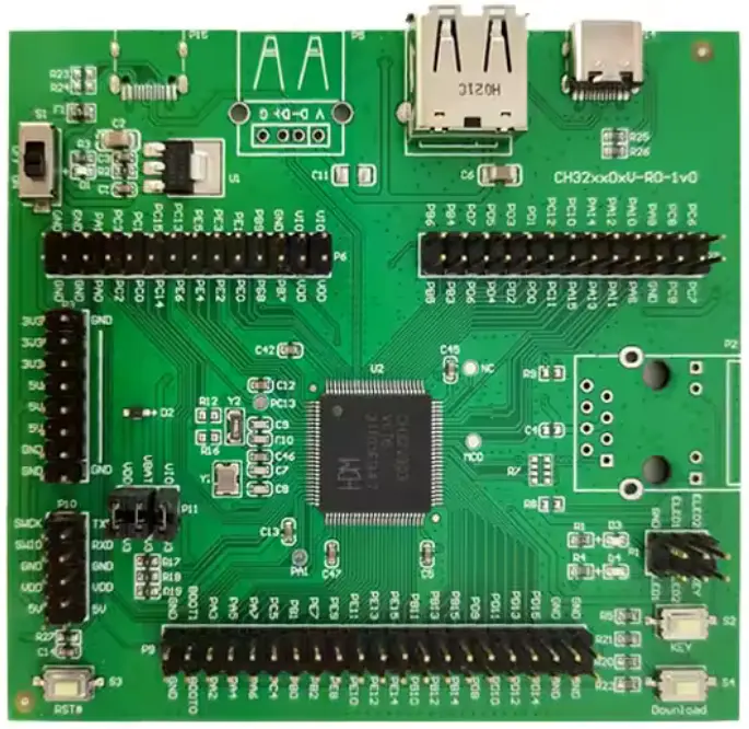 To illustrate this, we used a development board based on the CH32V303 SoC: the CH32V303-EVT. A description of this board can be found here (see page 5).
The CH32V303 is a MCU from WCH, based on the Qingke V4F processor, a RISC-V processor that can run at speeds up to 144 MHz.
We will explore the various files required to add support for any SoC and board, the specific files needed for this particular SoC/board, and how to upstream your changes to the Zephyr project.
The goal is to provide minimal support for the board—specifically, just enough to successfully run the Hello World sample.
This post is divided into two parts: first, we’ll cover how to add support for a new SoC, and then how to add support for a new board based on that SoC. If you’re working with a board that uses an already supported SoC, you can skip directly to the second part.
Supporting the SoC
The SoC directory
To add a new SoC in Zephyr, the first step is to create your soc directory. This directory should be placed under zephyr/soc/<VENDOR>/<your_soc>/. In many cases, other SoCs from the same vendor are already supported, so the structure of the zephyr/soc/<VENDOR>/ folder may be more complex.
Your SoC will be integrated into the Hardware Support Hierarchy: you’ll need to determine the appropriate SoC family and SoC series for your SoC.
You then need to add your SoC to the soc.yml file. When a SoC family is defined, this file is typically located in the corresponding family folder.
In our case, the soc.yml file (located at soc/wch/ch32v/soc.yml) looks like this:
family:
- name: ch32v
  series:
  - name: qingke-v2
    socs:
    - name: ch32v003
  - name: qingke-v4
    socs:
    - name: ch32v208
Since the CH32V303 is based on the Qingke V4F, it should be added to the qingke-v4 series, as follows:
family:
- name: ch32v
  series:
  - name: qingke-v2
    socs:
    - name: ch32v003
  - name: qingke-v4
    socs:
    - name: ch32v208
    - name: ch32v303
We then need to create the CMakeLists.txt file, which is used by the build system. This file should include the paths to the necessary include directories and source files required to build Zephyr for the SoC. Additionally, we need to specify the linker script. In our case, all these definitions are already provided at the family level:
add_subdirectory(${SOC_SERIES})

set(SOC_LINKER_SCRIPT ${ZEPHYR_BASE}/include/zephyr/arch/riscv/common/linker.ld CACHE INTERNAL "")
This instructs the build system to search all folders within the SoC series and use the default linker script for RISC-V. If your SoC requires a custom linker script, you will need to specify the path to your script using ${CMAKE_CURRENT_SOURCE_DIR}. For example, the rp2040 does this.
At the series level, we have the following:
zephyr_sources(
  soc_irq.S
  vector.S
)

zephyr_include_directories(.)
This file instructs the build system to compile the two assembly files, which we will discuss later. It also adds the current folder to the include directories, allowing the build system to locate pinctrl_soc.h, a file we will need. Since no additional source files are required at the SoC level, there is no need to create a CMakeLists.txt file inside our SoC folder.
Another file to create is soc.h. This file can contain macros or includes needed by other files. For many SoCs, this is where the HAL is included (see, for example, the stm32l5). The official documentation states that this file is mandatory; however, this is not always the case. For instance, all ARM SoCs require it, but in our case, it is not necessary.
Kconfig files
You will then need to create several Kconfig files. One important file is Kconfig.soc, which defines the Kconfig symbol for the SoC (as well as for the SoC family and series). In our case, for the existing SoCs, there are three relevant Kconfig.soc files:
soc/wch/ch32v/Kconfig.socdefines the SoC Familysoc/wch/ch32v/qingke_v4/Kconfig.socdefines the SoC seriessoc/wch/ch32v/qingke_v4/qingke_v4c/Kconfig.soc.ch32v208defines the SoC itself
Note that not all SoCs use three separate Kconfig.soc files. For example, the STM32 SoCs have one file for the family and one file for each series, which define both the SoC series and all the SoCs within that series.
It’s always best to follow the style used by the surrounding code. Therefore, we need to create a folder at soc/wch/ch32v/qingke_v4/qingke_v4f/, and then add the file Kconfig.soc.ch32v303 inside:
config SOC_CH32V303
	bool
	select SOC_SERIES_QINGKE_V4

config SOC
	default "ch32v303" if SOC_CH32V303
We define the symbol SOC_CH32V303, which selects the series and assigns the appropriate value to the symbol CONFIG_SOC. This symbol, SOC_CH32V303, will then be selected by any board using this SoC.
The other two Kconfig files are not mandatory but are often required.
First, the Kconfig file. You can use this file to add settings specific to your SoC, such as specifying the architecture. Note that you cannot change the default value of a Kconfig option that is not local to the SoC within this file. If you need to modify the default value of an external Kconfig option, you should use the third file, Kconfig.defconfig.
In our case, there is already a Kconfig file for the entire SoC family located at soc/wch/ch32v/Kconfig. This file selects various options, including the architecture (select RISCV), the image file type (select BUILD_OUTPUT_HEX), and others.
We now need to specify the options specific to our SoC in soc/wch/ch32v/qingke_v4/qingke_v4f:
config SOC_CH32V303
	select RISCV_ISA_RV32I
	select RISCV_ISA_EXT_M
	select RISCV_ISA_EXT_A
	select RISCV_ISA_EXT_C
	select RISCV_ISA_EXT_F
	select RISCV_ISA_EXT_ZICSR
	select RISCV_ISA_EXT_ZIFENCEI
This allows specifying the type of RISC-V core and its supported ISA. According to the QingKeV4 manual, the Qingke V4F ISA is RV32IMACF, supports CSR registers, and includes the fence.i instruction.
The last config file is the Kconfig.defconfig. This file allows you to set default values for certain Kconfig options. In our case, there are two Kconfig.defconfig files: one already defined for the SoC series at soc/wch/ch32v/qingke_v4/Kconfig.defconfig, and another that we will need to create, specific to our SoC.
The Kconfig.defconfig for all Qingke-V4 based SoCs defines several options, primarily setting the sizes of various stacks.
In the defconfig specific to our SoC, we need to set two options: VECTOR_TABLE_SIZE, defined in the Kconfig files of the SoC family, and NUM_IRQS. By consulting the reference manual, we can determine the appropriate values for these options. These values should only be set if our SoC is selected, so our Kconfig.defconfig file at soc/wch/ch32v/qingke_v4/qingke_v4f will look like this:
if SOC_CH32V303

config VECTOR_TABLE_SIZE
	default 103

config NUM_IRQS
	default 128

endif # SOC_CH32V303
With this, we are done with the Kconfig files.
soc_irq.S and vector.S
Our SoC requires two assembly files to function correctly.
Since the RISC-V standard does not specify how to handle IRQs exactly, each SoC must implement certain functions in a file named soc_irq.S. These functions are described in a comment in arch/riscv/core/isr.S:
Hence, the arch level code expects
 * the following functions to be provided at the SOC level:
 *
 *     - __soc_is_irq (optional): decide if we're handling an interrupt or an
         exception
 *     - __soc_handle_irq: handle SoC-specific details for a pending IRQ
 *       (e.g. clear a pending bit in a SoC-specific register)
For __soc_handle_irq, we don’t need to do anything, so we just return:
GTEXT(__soc_handle_irq)

SECTION_FUNC(exception.other, __soc_handle_irq)
	ret
For __soc_is_irq, the default code is working, so we don’t need to implement this one.
Next, we need to implement another file, vector.S, which is responsible for creating the interrupt vector and implementing the __start function.
This file will look like this:
/* Exports */
GTEXT(__start)

/* Imports */
GTEXT(__initialize)

SECTION_FUNC(vectors, ivt)
	.option norvc
	/* Jump to 0x08000008, into the main flash zone where j __start is */
	lui	x5, 0x8000
	jr	0x8(x5)
	j       __start
	.rept   CONFIG_VECTOR_TABLE_SIZE
	.word	_isr_wrapper
	.endr

SECTION_FUNC(vectors, __start)
	li 	a0, 0xf
	csrw	mtvec, a0
	j	__initialize
This code can be a bit complex to understand, so let’s break it down step by step.
First, we need to get familiar with the memory layout of the CH32V303, depicted below:
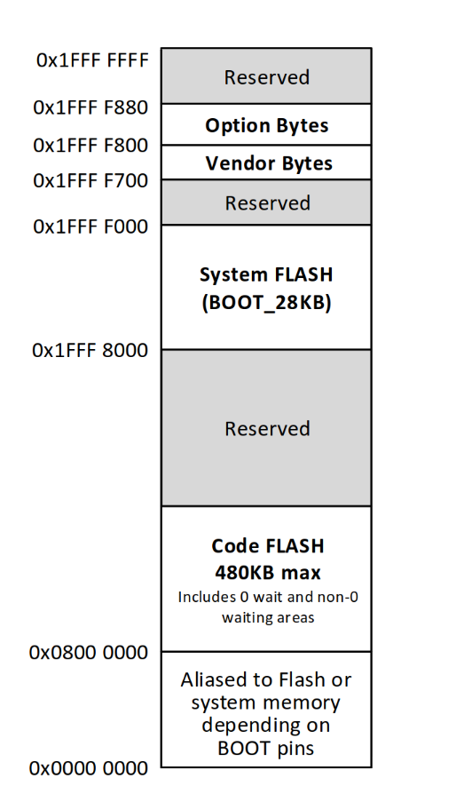
The flash memory (which contains the code) is located at 0x08000000. However, a small portion of the flash, called the “zero-wait” flash, is copied to RAM for faster access and is mapped at address 0. This is where the CPU begins execution. To use the full 480KB of flash for our code, we need to exit this aliased region and jump to the non-aliased flash area.
The first two instructions serve this purpose. The goal is to jump to the third instruction, j __start, but in the non-aliased flash region. The first instruction is located at 0x08000000, and since each RISC-V instruction is 4 bytes, the third instruction—our target—will be at 0x08000008. This is where we want to jump.
Here is a small table showing the first three instructions, along with their addresses in both aliased and non-aliased spaces. The CPU’s current access address is highlighted in yellow.
We see that after the second instruction, we execute the third instruction, but we are now in non-aliased space.
Before the __start function, we need to place the vector table. For each interrupt, the CPU jumps to the address specified in the vector table at the index corresponding to the interrupt number. In Zephyr, all interrupts call the same function, _isr_wrapper, which then handles the interrupt appropriately.
This means we simply need a large table filled with the address of _isr_wrapper. The following code does exactly that by placing the address of _isr_wrapper in memory CONFIG_VECTOR_TABLE_SIZE times.
	.rept   CONFIG_VECTOR_TABLE_SIZE
	.word	_isr_wrapper
	.endr
Then, in the __start function, we need to inform the CPU where the vector table is located. Since the table is placed just after the third instruction at 0x08000008, its address is 0x0800000C. In this code, the address is given in the aliased space, but that doesn’t matter because we will jump directly to the address of _isr_wrapper in the non-aliased space.
The __start function will first initialize the mtvec register. This register contains two fields: the address of the vector table (with the two least significant bits excluded), and two mode bits.
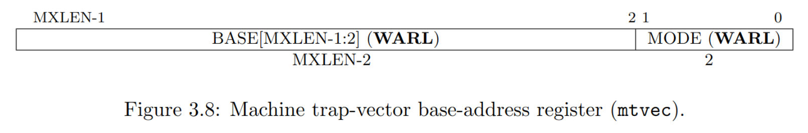
According to the datasheet for the Qingke-V4F, bit 0 of the mtvec register is set to 1 to indicate that we are using a vector table rather than a single address jump. Bit 1 is also set to 1 to specify that each vector entry contains an address, not an instruction that jumps to an address. This means we must write 0xf to the register. After that, we can jump to __initialize, which will start Zephyr.
	li 	a0, 0xf
	csrw	mtvec, a0
	j	__initialize
The Device Tree
Now that we have created our SoC folder, we need to write the Device Tree. The Device Tree is a data structure used to describe hardware. We need to create a .dtsi file that describes the hardware of our SoC. As always, when adding support for your SoC, it’s best to look at other SoCs from the same series, since their Device Tree files are likely to be similar.
First, we can see that in our case, inside dts/riscv/wch, there is a Device Tree file for the Qingke V4C, but not for the Qingke V4F — so we will have to create this file. This Device Tree declares three main components: the CPU model, the interrupt controller, and the systick timer. The last two are identical between the V4F and the V4C, so we can simply reuse those parts. Two components need to be updated: the CPU model and the exact ISA. The ISA differs slightly between the two CPUs: the V4F supports the F extension, which adds floating-point instructions.
We also need to change the compatible property from compatible = "wch,qingke-v4c"; to compatible = "wch,qingke-v4f";. Since we are introducing a new compatible string, we must declare a corresponding binding in dts/bindings/cpu/wch,qingke-v4f.yaml. This file is quite simple—it only needs to declare the CPU name and include the generic YAML file for all RISC-V CPUs.
description: WCH QingKe V4F RISC-V MCU

compatible: "wch,qingke-v4f"

include: riscv,cpus.yaml
We will put this in qingke-v4f.dtsi:
	cpus {
		#address-cells = <1>;
		#size-cells = <0>;

		cpu0: cpu@0 {
			device_type = "cpu";
			compatible = "wch,qingke-v4f";
			reg = <0>;
			riscv,isa = "rv32imacf_zicsr_zifencei";
		};
	};
The next step is an important one: it’s time to write the Device Tree of the SoC itself. We have to describe in this file all of the devices of the system. As always, the best way to write this is to start from a pre-existing .dtsi file from another SoC. For the CH32V303, we can simply copy and modify the Device Tree of the CH32V208. The CH32V208 and the CH32V303 are very similar, but they differ in the set of peripherals each includes.
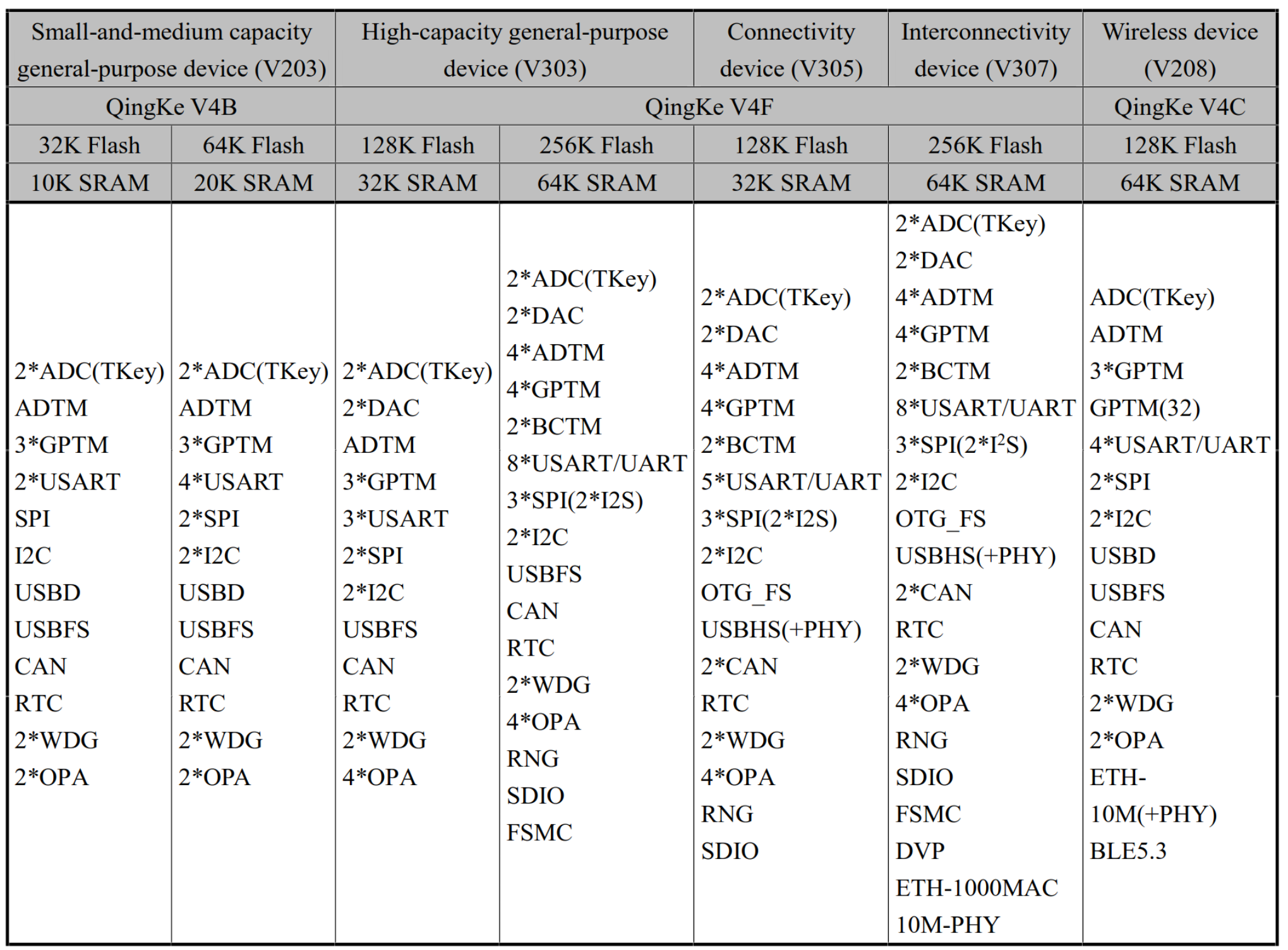
Not all of these devices are currently supported in Zephyr, so we only need to include in the Device Tree the ones that are supported. Let’s look at one example: the CH32V208 only has 4 UART devices, while the CH32V303 has 8.
To illustrate this, let’s take for example the case of adding the Device Tree description for the UART 5 controller:
		usart5: uart@40005000 {
			compatible = "wch,usart";
			reg = <0x40005000 0x20>;
			clocks = <&rcc CH32V20X_V30X_CLOCK_USART5>;
			interrupt-parent = <&pfic>;
			interrupts = <69>;
			status = "disabled";
		};
We see that we have to specify the compatible property (wch,usart), the reg property that indicates what is the address of the device in memory, which can be found in the datasheet:
![]()
We also have to give Zephyr the identifier of the clock that the driver will need to enable. This is defined in
include/zephyr/dt-bindings/clock/ch32v20x_30x-clocks.h
.
As this device can use interrupts, we have to put a reference to the interrupt controller (interrupt-parent property) and the interrupt number itself (interrupts property), here: 69, also indicated in the datasheet:
![]()
In a similar manner, we can add the Device Tree description for the three remaining UARTs, as well as for any other peripherals our SoC might include.
It’s important to note that many drivers for these peripherals already exist in Zephyr, since other SoCs from the same family use the same hardware blocks. If that wasn’t the case, we would need to develop the essential drivers ourselves—starting with at least the clock controller, pin control, and UART drivers, as these are the minimal components required to get Zephyr running on a new SoC.
With this, our SoC support is complete. Zephyr now understands how to build images targeting this SoC, but since Zephyr’s build system focuses on boards as the final target, the next step is to add support for our specific board.
Supporting the Board
The steps to add a new board are quite similar to those needed to add a new SoC.
First, you need to create a board directory, similar to the SoC directory. That means you have to decide the name that your board will have. You can use west boards to list all the already existing boards to avoid naming conflicts. In our case, the board is the CH32V303EVT. However, as we can see in this document, there are multiple boards named like this, with slightly different SoCs. To be able to differentiate them, we will name our board ch32v303vct6_evt, using the full SoC name for clarity.
We need to create the directory at boards/<vendor>/<board_name>, so in our case: boards/wch/ch32v303vct6_evt.
The first file to create is board.yml. This file contains a high-level description of the board: its name, vendor, the specific SoC it uses, and any variants if applicable.
The CH32V303EVT is fairly straightforward, featuring a single SoC with no variants. Therefore, the board.yml will look like this:
board:
  name: ch32v303vct6_evt
  full_name: WCH CH32V303VCT6_EVT
  vendor: wch
  socs:
    - name: ch32v303
Kconfig
Next, we need to create the file named Kconfig.<board_name>, which in our case is Kconfig.ch32v303vct6_evt. Similar to the Kconfig.soc and Kconfig.soc.ch32v303 files, this file will declare the Kconfig option associated with the board.
config BOARD_CH32V303VCT6_EVT
	select SOC_CH32V303
Note that this option selects the corresponding SoC. This is why you only need to specify the board you are building for in Zephyr, without explicitly indicating the specific SoC it uses.
For any additional Kconfig options that the board needs to create or modify, the process is similar to that of the SoC, involving the same types of files:
Kconfigfor board-specific settings. Similar to the SoC’sKconfigfile, this cannot modify settings outside the board’s scope. This file isn’t always required; many boards don’t use it. It’s mainly useful for defining new symbols introduced by the board or to modify the mainBOARD_<BOARD_NAME>option by adding selects, for example.Kconfig.defconfigis used to set default values for other Kconfig options. For instance, on the STM32L562E-DK board, the display controller requires configuring the correct pixel format. In theKconfig.defconfig, we see:if BOARD_STM32L562E_DK if DISPLAY choice ST7789V_PIXEL_FORMAT default ST7789V_BGR565 endchoice endif # DISPLAY endif # BOARD_STM32L562E_DK
In the case of the CH32V303EVT, no additional Kconfig options are needed, so these two files will not be used.
There is another Kconfig-related file in the board directory that does not exist in the SoC directory. This file is named <board_name>_defconfig; in our case, it will be ch32v303vct6_evt_defconfig. Unlike the Kconfig files used to define options, this file is in the .conf format (similar to the prj.conf file). It will be merged into the final .config file (which can be found after building at build/zephyr/.config). Here, we must specify settings that are required for all builds. Since the base build needs console support, we have to enable the necessary options:
CONFIG_SERIAL=y
CONFIG_CONSOLE=y
CONFIG_UART_CONSOLE=y
We also need to enable the GPIO driver, as it is responsible for configuring the pins.
CONFIG_GPIO=y
Most boards include these four options in their defconfig, along with any additional settings specific to their needs. For example, the STM32L562E-DK enables the MPU (Memory Protection Unit), so you’ll find CONFIG_ARM_MPU=y in its defconfig. In our case, no additional config options are required.
The Device Tree
An important remaining step is to describe the board hardware in a board-specific Device Tree file. In this file, you only need to specify the components present on the board itself, since all devices on the SoC are defined in the corresponding SoC Device Tree. Note that unlike the SoC Device Tree, the board Device Tree is located in the board/ directory, not in the dts/ folder.
First, we need to declare the model of the board and the chosen node. The chosen node tells Zephyr what devices to use for different tasks. For instance, if we want Zephyr to use USART1 for the console, we will have to specify zephyr,console = &usart1;.
Our main Device Tree ch32v303vct6_evt.dts will look like this:
#include <wch/ch32v303/ch32v303.dtsi>

/ {
	model = "ch32v303vct6_evt";
	compatible = "wch,ch32v303";

	chosen {
		zephyr,sram = &sram0;
		zephyr,flash = &flash0;
		zephyr,console = &usart1;
		zephyr,shell-uart = &usart1;
	};
};
Note that this time, we don’t use a .dtsi but a .dts: this file is the main Device Tree that will be compiled, and it includes the SoC-level definitions by including all .dtsi that it needs, in our case ch32v303.dtsi.
We also need to enable some devices, such as USART1, used for the console. For that, we need to set up the pin control for this device. We’re not going to go too much into the details here, we suggest to look at the documentation to learn more about it. The important part is that we are going to create another file, ch32v303vct6_evt-pinctrl.dtsi, that will declare the correct pin control configuration. In this file, we declare a node named usart1_default with the necessary information to allow the pin controller to configure the right pins for the USART. We will then need to include this file into our main .dts file.
#include <zephyr/dt-bindings/pinctrl/ch32v20x_30x-pinctrl.h>

&pinctrl {
	usart1_default: usart1_default {
		group1 {
			pinmux = <USART1_TX_PA9_0>;
			output-high;
			drive-push-pull;
			slew-rate = "max-speed-10mhz";
		};

		group2 {
			pinmux = <USART1_RX_PA10_0>;
			bias-pull-up;
		};
	};
};
We then can enable USART1 with the correct pin control and the correct baud rate:
&usart1 {
	status = "okay";
	current-speed = <115200>;
	pinctrl-0 = <&usart1_default>;
	pinctrl-names = "default";
};
We also need to set up the clocks that we want to use: this is highly specific to the board. In our case, we will configure the PLL clock to use the HSE clock, configure the frequency of the HSE, and tell the RCC (Reset and Clock Control) that we are using the PLL clock to drive the peripherals.
&clk_hse {
	clock-frequency = <DT_FREQ_M(32)>;
	status = "okay";
};

&pll {
	clocks = <&clk_hse>;
	status = "okay";
};

&rcc {
	clocks = <&pll>;
};
The CH32V303EVT doesn’t really have any additional devices on the board, so our Device Tree can stay like this. But here is how you can, for instance, add an I²C sensor that is on your board (example taken from the Arduino Nano 33 BLE device tree):
&i2c1 {
	compatible = "nordic,nrf-twim";
	status = "okay";
	pinctrl-0 = <&i2c1_default>;
	pinctrl-1 = <&i2c1_sleep>;
	pinctrl-names = "default", "sleep";

	lsm9ds1: lsm9ds1@6b {
		compatible = "st,lsm9ds1";
		reg = <0x6b>;
	};

};
west flash and west debug
Zephyr comes with a tool called west to help you build, flash, and debug your application. If you created your board and SoC correctly as described earlier in this blog post, west build is already supported.
But west flash and west debug need to use external tools (like OpenOCD). These tools are used through scripts/west_commands/runners. You then only need to configure the runners through a file named board.cmake.
In this file, you need to specify the arguments that you will pass to the runner (these are arguments to the Python script, not directly to the underlying program!), and include the CMake file for the runner that you will use. The CH32V303EVT can be flashed with OpenOCD and with minichlink, an open-source utility to flash SoCs of the CH32 family. So let’s create our own board.cmake:
board_runner_args(minichlink "--dt-flash=y")
include(${ZEPHYR_BASE}/boards/common/minichlink.board.cmake)

board_runner_args(openocd "--use-elf" "--cmd-reset-halt" "halt")
include(${ZEPHYR_BASE}/boards/common/openocd.board.cmake)
To be able to use OpenOCD, we need to provide it a configuration file, which we have to put in support/openocd.cfg. Note that the support for the CH32V303 is not upstream in OpenOCD: we have to use a fork to be able to interact with CH32V303 targets.
The documentation
If you will only use your board internally, you can skip this section. But if you intend to contribute your board upstream, it’s necessary to create the documentation page about your board.
For that, you can use a template at doc/templates/board.tmpl, or just copy and paste the documentation of a similar board as a starting point. The documentation needs to be put inside your board folder at doc/index.rst. You should also set an image for the board, named after the board (so for us, it will be doc/img/ch32v303vct6_evt.webp).
To build the documentation and verify that your page is formatted correctly, you should follow the instructions given in the official documentation.
You can see the documentation page of the CH32V303EVT at this page: https://docs.zephyrproject.org/latest/boards/wch/ch32v303vct6_evt/doc/index.html
Testing
We can now test our board. As this development board doesn’t have any LED directly linked to the SoC, we can’t use the “Blinky” sample. As a consequence, we will only test our board using the sample “Hello World”.
We can build and flash our image using west:
west build -p always -b ch32v303vct6_evt samples/hello_world/
west flash
Which gives us the intended result:
*** Booting Zephyr OS build v4.1.0-2911-g332e862a3a50 ***
Hello World! ch32v303vct6_evt/ch32v303
Upstreaming
Once your platform is supported, we recommend that you contribute your changes to the official Zephyr project, by submitting a pull request.
In our case, the support for the CH32V303 has been submitted in a pull request, and after several rounds of reviews, it was merged and will be part of the soon-to-be released 4.2 version of Zephyr!